SOLUTIONS MANUAL FOR 3d GRAPHICS FOR GAME PROGRAMMING EDITION 1 HAN
Bạn đang xem bản rút gọn của tài liệu. Xem và tải ngay bản đầy đủ của tài liệu tại đây (7.16 MB, 44 trang )
3
Chapter 2
1. Compute a 2D affine transform matrix that rotates a 2D point by θ
about a point (a, b), not about the origin.
2D rotation in the homogeneous coordinates is defined as follows:
cosθ −sinθ 0
sinθ cosθ 0
0
0 1
It is always about the origin. Therefore, rotating a point (x, y) about
(a, b) is implemented by concatenating three transforms: (1) translating
(x, y) by (−a, −b), (2) rotating the translated point about the origin,
and (3) back-translating the rotated point by (a, b). The matrices are
concatenated as follows:
1 0 −a
cosθ −sinθ 0
10a
M = 0 1 b sinθ cosθ 0 0 1 −b
00 1
0
0 1
0 0 1
cosθ −sinθ −acosθ + bsinθ + a
= sinθ cosθ −asinθ − bcosθ + b
0
0
1
2. In linear algebra, it is proven that the inverse of a rotation is simply
its transpose. Given two non-standard orthonormal bases {a,b,c} and
{d,e,f }, compute a 3×3 matrix that converts the vector defined in terms
of {a,b,c} into the vector of {d,e,f }.
The vector defined in terms of {a,b,c} is first transformed into the vector
defined in terms of the standard basis {e1 ,e2 ,e3 }, and then transformed
into the vector defined in terms of {d,e,f }. The first transform is implemented by the following basis-change matrix:
ax bx cx
ay by cy
az bz cz
The second transform is implemented by the following basis-change matrix:
dx dy dz
ex ey ez
fx fy fz
4
When they are
dx
ex
fx
combined, we obtain the following:
dy dz
ax bx cx
a·d b·d
ey ez ay by cy = a · e b · e
fy fz
az bz cz
a·f b·f
c·d
c·e
c·f
3. Let us define a matrix for scaling along 3 orthonormal vectors, a, b, and
c, which are not identical to the standard basis vectors e1 , e2 , and e3 .
The scaling factors are sa , sb , and sc along a, b, and c, respectively. It
is also observed that a × b = c where × denotes the cross product. The
scaling matrix is a combination of three 3×3 matrices. Compute the
three matrices.
Scaling a vector (x, y, z) along the non-standard orthonormal basis {a,b,c}
is implemented by concatenating three transforms: (1) basis change from
{e1 ,e2 ,e3 } to {a,b,c}, (2) scaling, and (3) basis change from {a,b,c} to
{e1 ,e2 ,e3 }. The matrices are concatenated as follows:
ax bx cx
ax ay az
sx 0 0
ay by cy 0 sy 0 bx by bz
0 0 sz
cx cy cz
az bz cz
4. The view transform consists of a translation and √
a rotation. We are given
the following view parameters: EYE = (0, 0, − 3), AT = (0,0,0), and
UP = (0,1,0).
(a) Compute the translation.
1
0
0
0
0
1
0
0
0
0
1
0
0
√0
3
1
(b) Compute the rotation.
EYE is located at −z axis, and looks at AT that is the origin.
Therefore, n is (0,0,−1). UP is (0,1,0), and is already orthogonal
to n. Applying the right-hand rule to UP and n finds that u is
5
(−1, 0, 0). Applying the right-hand rule to n and u finds that v is
(0, 1, 0). The rotation matrix is then as follows:
−1 0 0 0
0 1 0 0
0 0 −1 0
0 0 0 1
5. Section 2.4.3 derives the projection matrix assuming that the z -range of
the cuboidal view volume is [−1,0]. In OpenGL, the z -range is [−1,1].
Derive the projection matrix for OpenGL presented in Equation (2.25).
In OpenGL, the xy-ranges are the same as those in this book, [−1,1].
Therefore Equation (2.33) is valid, and we have the following equation:
z = −m3 −
m4
z
The difference is that the z -coordinates −f and −n are mapped to −1
and 1 (not 0), respectively, by the OpenGL projection transform. In
other words, we have two known pairs of (z,z ): (−f ,−1) and (−n,1).
Putting them into the above equation, we obtain the following:
−1 = −m3 +
1 = −m3 +
m4
f
m4
n
Solving the above equations for m3 and m4 gives
m3 =
m4 =
f +n
f −n
2nf
f −n
Finally, both m3 and m4 are negated to be transformed to the lefthanded clip space. Then, Equation (2.25) is obtained.
6
Chapter 3
1. A viewport’s corners are located at (10,20,1) and (100,200,2).
(a) Compute the reflection matrix for the viewport transform.
1 0
0 −1
0 0
0 0
00
0 0
1 0
01
(b) Compute the scaling matrix.
The width of the viewport is 90, the height is 180, and the depth
is 1. Therefore, we have the following scaling matrix:
45 0 0 0
0 90 0 0
0 0 1 0
0 0 01
(c) Compute the translation matrix.
The center of the viewport’s front face is (55,110,1). Therefore, we
have the following translation matrix:
1 0 0 55
0 1 0 110
0 0 1 1
000 1
FIGURE 2.1
The vertex processing and fragment processing stages (in rounded boxes) are programmable, and the rasterization and output merging
stages (in rectangles) are hard-wired.
FIGURE 2.2
Transforms and spaces in the vertex processing stage. Sections 2.1, 2.2, and 2.4 present the three transforms in order.
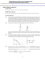
FIGURE 2.3
A vector p is rotated by θ to define a new vector p′.
FIGURE 2.4
The sphere and teapot are defined in their own object spaces and are assembled into a single space, the world space.
FIGURE 2.5
The teapot is rotated about the y-axis by 90° and is then translated along the x-axis by seven units. The teapot’s mouth is rotated from (0,2,3)
to (3,2,0) and then translated to (10,2,0). The combined matrix of the rotation and the translation instantly transforms (0,2,3) to (10,2,0).
FIGURE 2.6
The teapot shown in the middle is rotated CCW to define the one on the left. If rotated CW, we have the result on the right.
FIGURE 2.7
The teapot is successively rotated using the Euler angles and acquires an orientation.
FIGURE 2.8
Vertex transform vs. normal transform (modified from [8]). (a) The vertices and normal are transformed by a single matrix M. The transformed normal is not orthogonal to the transformed triangle. (b) Whereas the vertices are transformed by M, the normal is transformed by
(M−1)T. After the transforms, the normal remains orthogonal to the triangle.
FIGURE 2.9
Before transforms, n is orthogonal to the triangle 〈 p,q,r〉. Whereas 〈 p,q,r〉 is transformed by M, n is transformed by (M−1)T. Then, the transformed normal n′ remains orthogonal to the transformed triangle 〈 p′,q′,r′〉.
FIGURE 2.10
Given EYE, AT, and UP, the camera space is defined. Its origin is EYE, and the basis is {u,v,n}. In terms of the camera space, the camera
is located at the origin and points in the −n direction, i.e., the view direction is −n.
FIGURE 2.11
The camera space {EYE, u,v,n} is superimposed onto the world space {O,e1,e2,e3}. It is done by a translation followed by a rotation. The two
transforms are combined to produce the view transform, which converts the world-space objects into the camera space.
FIGURE 2.12
The first is the standard basis for R2. The second is a valid basis for R2, but is neither standard nor orthonormal. The third is not the standard
but an orthonormal basis.
FIGURE 2.13
The vertex position and normal are denoted by p and n, respectively. Once the light source and camera positions are defined, l, r, and v are
obtained. Then, lighting can be computed per vertex.
FIGURE 2.14
The pyramid-like volume is named view frustum. The polygons outside the view frustum (illustrated in red) are considered invisible.
FIGURE 2.15
If a polygon intersects the view frustum’s boundary, the part of the polygon outside the view frustum is discarded.
FIGURE 2.16
Projection transform. (a) The view frustum is deformed into a cuboid. The deformation named projection transform is in fact applied to the
objects in the scene. Observe how the teapot is deformed. (b) Cross-section views show how the perspective projection effect (called foreshortening) is achieved through projection transform.
FIGURE 2.17
The z-coordinates are negated for switching from the right-handed clip space to the left-handed clip space. Z-negation is equivalent to the
z-axis inversion.
FIGURE 2.18
The last transform in the vertex processing stage, Mproj, converts the right-handed camera-space objects into the left-handed clip space. This
illustrates the combination of Fig. 2.16-(a) and Fig. 2.17.
FIGURE 2.19
Computing projection matrix. (a) Normalized coordinate y′ is computed. (b) The aspect ratio can be defined in terms of fovx and fovy.
FIGURE 2.20
The projection transform converts the z-range [−f,−n] to [−1,0].
FIGURE 2.1
The vertex processing and fragment processing stages (in rounded boxes) are programmable, and the rasterization and output merging
stages (in rectangles) are hard-wired.