Section15 Pressure Vessel Design
Bạn đang xem bản rút gọn của tài liệu. Xem và tải ngay bản đầy đủ của tài liệu tại đây (108.13 KB, 10 trang )
†
Text Eq. refers to Mechanical Engineering Design, 7
th
edition text by Joseph Edward Shigley, Charles
R. Mischke and Richard G. Budynas; equations and figures with the prefix T refer to the present tutorial.
M
ECHANICAL
E
NGINEERING
D
ESIGN
T
UTORIAL
4 –15: P
RESSURE
V
ESSEL
D
ESIGN
P
RESSURE
V
ESSEL
D
ESIGN
M
ODELS FOR
C
YLINDERS
:
1. Thick-walled Cylinders
2. Thin-walled Cylinders
T
HICK
-
WALL
T
HEORY
• Thick-wall theory is developed from the Theory of Elasticity which yields the state of
stress as a continuous function of radius over the pressure vessel wall. The state of
stress is defined relative to a convenient cylindrical coordinate system:
1.
t
σ
— Tangential Stress
2.
r
σ
— Radial Stress
3.
l
σ
— Longitudinal Stress
• Stresses in a cylindrical pressure vessel depend upon the ratio of the inner radius to
the outer radius ( /
oi
rr) rather than the size of the cylinder.
• Principal Stresses (
123
,,
σσσ
)
1. Determined without computation of Mohr’s Circle;
2. Equivalent to cylindrical stresses ( , ,
trl
σσσ
)
• Applicable for any wall thickness-to-radius ratio.
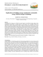
Cylinder under Pressure
Consider a cylinder, with capped ends, subjected to an internal pressure, p
i
, and an
external pressure, p
o
,
FIGURE T4-15-1
o
p
o
r
i
r
i
p
l
σ
r
σ
t
σ
r
σ
l
σ
t
σ
Shigley, Mischke & Budynas Machine Design Tutorial 4–15: Pressure Vessel Design 2/10
The cylinder geometry is defined by the inside radius, ,
i
r the outside radius, ,
o
r and the
cylinder length, l. In general, the stresses in the cylindrical pressure vessel ( , ,
trl
σσσ
)
can be computed at any radial coordinate value, r, within the wall thickness bounded by
i
r and ,
o
r and will be characterized by the ratio of radii, / .
oi
rr
ζ
= These cylindrical
stresses represent the principal stresses and can be computed directly using Eq. 4-50 and
4-52. Thus we do not need to use Mohr’s circle to assess the principal stresses.
Tangential Stress:
22
22222
/)(
io
iooiooii
t
rr
rpprrrprp
−
−−−
=
σ
for
io
rrr≤≤ (Text Eq. 4-50)
Radial Stress:
22
22222
/)(
io
iooiooii
r
rr
rpprrrprp
−
−+−
=
σ
for
io
rrr≤≤ (Text Eq. 4-50)
Longitudinal Stress:
• Applicable to cases where the cylinder carries the longitudinal load, such as
capped ends.
• Only valid far away from end caps where bending, nonlinearities and stress
concentrations are not significant.
22
22
io
ooii
l
rr
rprp
−
−
=
σ
for
io
rrr≤≤ (Modified Text Eq. 4-52)
Two Mechanical Design Cases
1. Internal Pressure Only ( 0=
o
p )
2. External Pressure Only ( 0=
i
p )
Design Case 1: Internal Pressure Only
• Only one case to consider — the critical section which exists at
i
rr = .
• Substituting 0=
o
p into Eqs. (4-50) and incorporating / ,
oi
rr
ζ
= the
largest value of each stress component is found at the inner surface:
22
2
,max
22 2
1
()
1
oi
tit i i iti
oi
rr
rr p p pC
rr
ζ
σσ
ζ
+
+
== = = =
−−
(T-1)
Shigley, Mischke & Budynas Machine Design Tutorial 4–15: Pressure Vessel Design 3/10
where
22
2
222
1
1
oi
ti
oi
rr
C
rr
ζ
ζ
+
+
==
−−
is a function of cylinder geometry only.
irir
prr −===
max,
)(
σσ
Natural Boundary Condition (T-2)
• Longitudinal stress depends upon end conditions:
ili
p C
Capped Ends (T-3a)
l
σ
=
0
Uncapped Ends (T-3b)
where
2
1
1
li
C
ζ
=
−
.
Design Case 2: External Pressure Only
• The critical section is identified by considering the state of stress at two
points on the cylinder: r = r
i
and r = r
o
. Substituting p
i
= 0 into Text
Eqs. (4-50) for each case:
r = r
i
0)( ==
ir
rr
σ
Natural Boundary Condition (T-4a)
()
2
2
,max
22 2
2
2
1
o
tit o o oto
oi
r
rr p p pC
rr
ζ
σσ
ζ
= = =− =− =−
−−
(T-4b)
where,
2
2
222
2
2
1
o
to
oi
r
C
rr
ζ
ζ
==
−−
.
r = r
o
oror
prr −===
max,
)(
σσ
Natural Boundary Condition (T-5a)
22
2
22 2
1
()
1
oi
to o o oti
oi
rr
rr p p pC
rr
ζ
σ
ζ
+
+
==− =− =−
−−
(T-5b)
• Longitudinal stress for a closed cylinder now depends upon external
pressure and radius while that of an open-ended cylinder remains zero:
olo
p C− Capped Ends (T-6a)
l
σ
=
0
Uncapped Ends (T-6b)
Shigley, Mischke & Budynas Machine Design Tutorial 4–15: Pressure Vessel Design 4/10
where
2
2
1
lo
C
ζ
ζ
=
−
.
Example T4.15.1: Thick-wall Cylinder Analysis
Problem Statement:
Consider a cylinder subjected to an external pressure of
150 MPa and an internal pressure of zero. The cylinder has a 25 mm ID and a 50
mm OD, respectively. Assume the cylinder is capped.
Find:
1. the state of stress (
r
σ
,
t
σ
,
l
σ
) at the inner and outer cylinder
surfaces;
2. the Mohr’s Circle plot for the inside and outside cylinder surfaces;
3. the critical section based upon the estimate of
max
τ
.
Solution Methodology:
Since we have an external pressure case, we need to compute the state of
stress ( ,
r
σ
,
t
σ
l
σ
) at both the inside and outside radius in order to determine
the critical section.
1. As the cylinder is closed and exposed to external pressure only,
Eq. (T-6a) may be applied to calculate the longitudinal stress
developed. This result represents the average stress across the wall
of the pressure vessel and thus may be used for both the inner and
outer radii analyses.
2. Assess the radial and tangential stresses using Eqs. (T-4) and (T-5)
for the inner and outer radii, respectively.
3. Assess the principal stresses for the inner and outer radii based
upon the magnitudes of ( ,
r
σ
,
t
σ
l
σ
) at each radius.
4. Use the principal stresses to calculate the maximum shear stress at
each radius.
5. Draw Mohr’s Circle for both states of stress and determine which
provides the critical section.
Solution:
1. Longitudinal Stress Calculation:
OD 50mm ID 25mm
25mm; 12.5mm
22 22
oi
rr== = == =
Compute the radius ratio,
ζ
25 mm
2.0
12.5 mm
o
i
r
r
ζ
== =
Shigley, Mischke & Budynas Machine Design Tutorial 4–15: Pressure Vessel Design 5/10
Then,
22
22
2
2
2
(2)
1(2) 1
( ) ( ) ( 150MPa)(1.3333 mm )
1
lo
lilo o olo
C
rr rr p pC
ζ
ζ
ζ
σσ
ζ
== =
−−
== = =− =− =−
−
2
1.3333 mm
MPa200
−
−−
−=
==
=
l
σ
σσ
σ
2. Radial & Tangential Stress Calculations:
Inner Radius (r = r
i
)
22
22
2
,max
22
22(2)
1(2)1
2
( ) ( 150MPa)(2.6667)
to
o
tit o oto
oi
C
r
rr p pC
rr
ζ
ζ
σσ
== =
−−
== =− =− =−
−
2.6667
400 MPa
ti
σ (r r ) Compressive==−
0pforConditionBoundaryNatural
i
===
0)r(rσ
ir
Outer Radius (r = r
o
)
2
2
22
22
,min
22
1(2)1
1(2)1
( ) ( 150MPa)(1.6667)
ti
oi
tot o oti
oi
C
rr
rr p pC
rr
ζ
ζ
σσ
++
== =
−−
+
= = =− =− = −
−
1.6667
eCompressiv
MPa250
−
−−
−=
==
==
==
=
)r(rσ
ot
ConditionBoundaryNatural
MPa150
−
−−
−=
==
=−
−−
−=
==
==
==
=
oir
p)r(rσ
3. Define Principal Stresses:
Inner Radius (r = r
i
) Outer Radius (r = r
o
)
MPa400
MPa200
MPa0
3
2
1
−==
−==
==
t
l
r
σσ
σσ
σσ
MPa250
MPa200
MPa150
3
2
1
−==
−==
−==
t
l
r
σσ
σσ
σσ
4. Maximum Shear Stress Calculations:
Inner Radius (r = r
i
)
13
max
0 ( 400)
()
22
i
rr
σσ
τ
−
−−
== = =
200 MPa