The A-Interface
Bạn đang xem bản rút gọn của tài liệu. Xem và tải ngay bản đầy đủ của tài liệu tại đây (294.9 KB, 14 trang )
10
The A-Interface
On the physical level, the A-interface consists of one or more PCM links
between the MSC and the BSC, each with a transmission capacity of 2 Mbps.
The TRAU, which typically is located between the MSC and the BSC, has to
be taken into consideration when examining this interface. Consequently, the
A-interface can be separated into two parts.
•
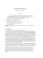
The first part is between the BTS and the TRAU, where the transmit-
ted payload still is compressed. Figure 10.1 shows a possible channel
configuration for three trunks. As on the Abis-interface, a single traffic
channel occupies only two of the eight bits of a PCM channel. That
is why it is possible to transport four fullrate traffic channels on one
PCM channel. The exceptions are TSs, where signaling information is
carried. Signaling information requires the entire 64 Kbps of a channel
(e.g., TS 16 in Figure 10.1).
•
The second part of the A-interface is the one between the TRAU and
the MSC. There, all data are uncompressed. For that reason, every
traffic channel requires the complete 8 bits or occupies an entire
64-Kbps PCM channel. The position of a signaling channel may be
different before and after the TRAU, as Figure 10.1 shows.
10.1 Dimensioning
An examination of the channel configuration in Figure 10.1 makes it obvious
that the transmission resources between the BSC and the TRAU are used only
171
172GSMNetworks:Protocols,Terminology,andImplementation
B
S
C
FAS/NFAS
0
1
2
3
16
28
29
30
31
SS7—Signaling
not used
not used
not used
TCH
TCH
TCH
TCH
TCH
TCH
FAS/NFAS
SS7—Signaling
16
20
21
22
30
31
0
FAS/NFAS
0
1
2
3
16
28
29
30
31
SS7—Signaling
not used
not used
not used
TCH
TCH
TCH
TCH
TCH
TCH
T
R
A
U
M
S
C
FAS/NFAS
0
1
2
3
20
28
29
30
31 TCH
TCH
TCH
TCH
TCH
TCH
TCH
SS7—Signaling
A-interface
MSC location
BSC location
1
2
3
5
4
6
Trunk 1 / channel 0 data
15
14
TS 1 TS 2 TS 3 TS 4
TS 1 TS 2 TS 3 TS 4
TS 5 TS 6 TS 7 TS 8
TS 1 TS 2 TS 3 TS 4
TS 5 TS 6 TS 7 TS 8
TS 13 TS 14 TS 15
TS 13 TS 14 TS 15
from trunk 1
from trunk 2
from trunk 2
from trunk 3
from trunk 3
17
18
19
TS 17 TS 18 TS 19 TS 20
TS 17 TS 18 TS 19 TS 20
TS 17 TS 18 TS 19 TS 20
TS 21 TS 22 TS 23 TS 24
TS 21 TS 22 TS 23 TS 24
from trunk 2
from trunk 3
TS 29 TS 30 TS 31
TS 29 TS 30 TS 31
from trunk 2
from trunk 3
not used
n.u.
n.u.
n.u.
n.u.
Trunk 3
Trunk 2
Trunk 1
Trunk 3
Trunk 2
Trunk 1
from trunk 1
Figure 10.1 Possible channel configuration between the BSC and the MSC.
inefficiently. Only 2 bits of the PCM channel are actually occupied, while the
remaining 6 bits stay vacant. In that respect, the A-interface between the BSC
and the TRAU can be compared to the Abis-interface in a star configuration.
It is possible, by means of multiplexing, to transport the data of several
trunks from the BSC over only one physical 2-Mbps link before the data are
actually handed over to the TRAU for decompression. That allows a savings of
about two-thirds of the line costs if the TRAU is installed at the MSC location.
Multiplexing between the TRAU and the MSC does not deserve any considera-
tion, since every traffic channel there requires 64 Kbps.
10.2 Signaling Over the A-Interface
As on all the other interfaces except for the Air-interface and the Abis-interface,
the A-interface uses SS7 with the SCCP as the user part. Similar to the Abis-
interface, GSM uses an already existing signaling standard (SS7 plus SCCP) on
the A-interface and simply defines a new application.
This new application is the BSSAP, which itself can be separated into the
base station subsystem management application part (BSSMAP) and the direct
transfer application part (DTAP).
That results in the OSI protocol stack are presented in Figure 10.2.
DTAP data are user information and therefore completely transparent for the
A-interface, while the BSSMAP data are part of Layer 3.
10.2.1 The Base Station Subsystem Application Part
The BSSAP, with its two parts, the DTAP and the BSSMAP, represents the
GSM-specific user signaling on the A-interface.
The A-Interface
173
SCCP
MTP 1–3
{
{
User data
Layer 1–3
BSSAP
DTAP
BSSMAP
Figure 10.2. The A-interface in the OSI protocol stack.
•
The BSSMAP includes all messages exchanged between the BSC and
the MSC that are actually processed by the BSC. Examples are
PAGING, HND_CMD, and the RESET message. More generally,
the BSSMAP comprises all messages exchanged as RR messages
between the MSC and the BSC, as well as messages used for control
tasks between the BSC and the MSC.
•
The DTAP comprises all messages exchanged between a subsystem of
the NSS and the MS. The messages are transparent for the BSS. This
definition applies to all but three messages of MM. These exceptions
are the LOC_UPD_REQ, the IMSI_DET_IND, and the
CM_SERV_REQ messages. All three are part of DTAP but neverthe-
less are partly processed by the BSC.
Figure 10.3 illustrates the task sharing between BSSMAP and DTAP. It is
important to note that there is not a 100% correspondence between DTAP and
CC/MM on one side and BSSMAP and RR on the other. There are cases when
the BSC and the MS exchange RR messages without informing the MSC about
the content of the messages. The same applies for BSSMAP messages between
the BSC and the MSC.
10.2.2 The Message Structure of the BSSAP
Figure 10.4 shows the general structure of BSSAP messages. The entire BSSAP
message is embedded in an SCCP message. The first 8 or 16 bits of the
BSSAP distinguish between BSSMAP and DTAP. The DTAP header is
174 GSM Networks: Protocols, Terminology, and Implementation
M
O
B
I
L
E
S
T
A
T
I
O
N
B
S
S
Mobility mgt. (MM)
Radio
resource
management
(RR)
Call control (CC)
DTAP
M
S
C
BSSMAP
Figure 10.3 The relation between DTAP corresponding to CC and MM, and BSSMAP corre-
sponding to RR.
2 bytes (16 bits) long and consists of the discrimination parameter (01 = DTAP)
and the data link connection identifier (DLCI). The first 3 bits of the DLCI
identify the service access point identifier (SAPI), which is used on the Air-
interface (SAPI = 0 for RR, MM, and CC; SAPI = 3 for SMS and SS).
The BSSMAP header is only 1 byte (8 bits) long and consists only of the
discrimination parameter (00 = BSSMAP). In BSSMAP, there is no DLCI
octet.
A length indicator, indicating the length of the following data field, fol-
lows the header in both cases of BSSMAP and DTAP. DTAP messages exactly
follow the format as presented in Figure 7.14. BSSMAP messages are formatted
as shown in Figure 10.5. The actual parameters follow the 1-octet-long message
type. Independent of being mandatory or optional, each parameter always
consists of an information element identifier (IEI), length indicator, and the
actual data.
The A-Interface
175
BSSMAP/DTAP
length 8 bit
Data (BSSAP)
8 bit
8 bit
01234567
SCCP SCCP
Discrimination parameter (01 DTAP)==>
Discrimination parameter (00 BSSMAP)==>
DLCI (data link connection identifier) =>
0
000
0
010
0
000
S
3
0S
1
S
2
8 bit
16 bit
1. byte
2. byte
{
{
DTAP messages
Header 2 byte=
BSSMAP messages
Header 1 byte=
S , S , S identify the SAPI on the Air-interface
123
=>
0
000
0
000
01234567
Figure 10.4 The format of BSSAP messages.
1 byte
Parameter A
Parameter B
Parameter C
Parameter N-1Parameter N
MT Message type=>
Data Length IEI
…
Optional parameter
Mandatory parameter
MT
{
{
Figure 10.5 The internal structure of BSSMAP messages.