The Abis-Interface
Bạn đang xem bản rút gọn của tài liệu. Xem và tải ngay bản đầy đủ của tài liệu tại đây (291.3 KB, 37 trang )
6
The Abis-Interface
The Abis-interface is the interface between the BTS and the BSC. It is a PCM
30 interface, like all the other terrestrial interfaces in GSM. It is specified by
ITU in the G-series of recommendations. The transmission rate is 2.048 Mbps,
which is partitioned into 32 channels of 64 Kbps each. The compression tech-
niques that GSM utilizes packs up to 8 GSM traffic channels into a single
64-Kbps channel. GSM never specified the Abis-interface in every detail, as was
also the case with the B-interface (the interface between the MSC and the
VLR). The Abis-interface is regarded as proprietary, which leads to variations
in the Layer 2 protocol between manufacturers, as well as to different channel
configurations. The consequence is that, normally, a BTS from manufacturer A
cannot be used with a BSC from manufacturer B.
6.1 Channel Configurations
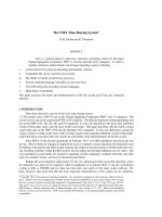
Figure 6.1 presents two possible channel configurations of the Abis-interface.
Note the fixed mapping of the air-interface traffic channels (Air0, Air1, …)
onto a time slot of the Abis-interface. This fixed mapping has the advantage
that it is possible to determine which Abis time slot will be used when a particu-
lar air-interface channel is assigned.
51
6.2 Alternatives for Connecting the BTS to the BSC
The line resources on the Abis-interface usually are not used efficiently. The
reason is that a BTS, typically, has only a few TRXs, which implies small traffic
volume capability. Consequently, the line between the BTS and the BSC
is used only to a fraction of its capacity. Figure 6.1(a), the star configuration,
shows the case of a BTS with four TRXs, in which only 47% of the 2 Mbps
52 GSM Networks: Protocols, Terminology, and Implementation
bit
TS 76543210
0
FAS / NFAS
1
Air 0 Air 1 Air 2 Air 3
BTS 1 / TRX 1
2
Air 4 Air 5 Air 6 Air 7
3
Air 0 Air 1 Air 2 Air 3
BTS 3 / TRX 1
4
Air 4 Air 5 Air 6 Air 7
5
Air 0 Air 1 Air 2 Air 3
BTS 1 / TRX 2
6
Air 4 Air 5 Air 6 Air 7
7
Air 0 Air 1 Air 2 Air 3
BTS 3 / TRX 2
8
Air 4 Air 5 Air 6 Air 7
9
Air 0 Air 1 Air 2 Air 3
BTS 2 / TRX 1
10
Air 4 Air 5 Air 6 Air 7
11
Air 0 Air 1 Air 2 Air 3
BTS 4 / TRX 1
12
Air 4 Air 5 Air 6 Air 7
13
Air 0 Air 1 Air 2 Air 3
BTS 2 / TRX 2
14
Air 4 Air 5 Air 6 Air 7
15
Air 0 Air 1 Air 2 Air 3
BTS 4 / TRX 2
16
Air 4 Air 5 Air 6 Air 7
17
not used
18
partial O&M data
19
BTS 4 / TRX 2 signaling
20
BTS 4 / TRX 1 signaling
21
BTS 3/ TRX 2 signaling
22
BTS 3/ TRX 1 signaling
23
BTS 2/ TRX 2 signaling
24
BTS 2/ TRX 1 signaling
25
BTS 1/ TRX 2 signaling
26
BTS 1/ TRX 1 signaling
27
BTS 4 / O&M signaling
28
BTS 3 / O&M signaling
29
BTS 2 / O&M signaling
30
BTS 1 / O&M signaling
31
Transmission control
information
bit
TS76543210
0
FAS / NFAS
1
Air 0 Air 1 Air 2 Air 3
TRX 1
2
Air 4 Air 5 Air 6 Air 7
3
Air 0 Air 1 Air 2 Air 3
TRX 5
4
Air 4 Air 5 Air 6 Air 7
5
Air 0 Air 1 Air 2 Air 3
TRX 2
6
Air 4 Air 5 Air 6 Air 7
7
Air 0 Air 1 Air 2 Air 3
TRX 6
8
Air 4 Air 5 Air 6 Air 7
9
Air 0 Air 1 Air 2 Air 3
TRX 3
10
Air 4 Air 5 Air 6 Air 7
11
Air 0 Air 1 Air 2 Air 3
TRX 7
12
Air 4 Air 5 Air 6 Air 7
13
Air 0 Air 1 Air 2 Air 3
TRX 4
14
Air 4 Air 5 Air 6 Air 7
15
Air 0 Air 1 Air 2 Air 3
TRX 8
16
Air 4 Air 5 Air 6 Air 7
17
not used
18
not used
19
partial O&M data
20
not used
21
O&M signaling
22
TRX 8 signaling
23
TRX 7 signaling
24
TRX 6 signaling
25
TRX 5 signaling
26
not used
27
TRX 4 signaling
28
TRX 3 signaling
29
TRX 2 signaling
30
TRX 1 signaling
31
not used
(a) (b)
Air 4
Figure 6.1 (a) Star configuration (fullrate) and (b) serial connection (four BTSs with two
TRX each).
actually is needed. The shaded areas mark the unused channels. When the BTS
has only one TRX, that value goes down to 16%. Such waste of resources has
a historical background, and it would not change much if halfrate channels
were used.
When GSM specified the BTS, it defined that a BTS may have up to
16 TRXs. Two 2-Mbps interfaces are required to connect such a BTS to the
BSC, because a single 2-Mbps interface is able to support only up to 10 TRXs,
including O&M signaling.
Proportionally fewer resources are required on the Abis-interface when a
BTS with a smaller number of TRXs is installed. The remainder cannot easily
be used.
Experience has shown that the optimum for a BTS is in the range of one
to four TRXs. This compromise reflects several parameters:
•
Capacity. How many traffic and signaling channels does a BTS need
to provide, on average and during busy hours, to avoid an overload
condition?
•
Available frequency range. What is the minimum distance between
BTSs beyond which a given TRX frequency may be reused?
Network operators worldwide have had bad experiences, particularly with the
latter point.
When digital radio was introduced, the assumption was that the impact
of the disturbances, same-channel interference or neighbor channel interfer-
ence, would be relatively minor. Soon after the introduction of commercial
service, that assumption was found to be wrong, when more and more interfer-
ence problems between BTSs appeared and degraded the quality of service.
Problems with large, powerful cells were experienced, particularly in urban
areas and city centers, where more and more minicells and microcells are
being used.
The conclusion was to move in the direction of using more cells with
fewer TRXs and smaller output power (<1W) rather than in the direction of
fewer cells with more TRXs and high output power. That configuration
requires a larger number of BTSs than the alternative to cover any given area.
Connecting the larger number of BTSs to the BSCs, in turn, requires a larger
number of links (Abis-interfaces).
Because of that trend, together with the high costs for links between the
BTS and the BSC and the low efficiency when using such links, another con-
figuration was introduced, the serial connection of BTSs.
The Abis-Interface
53
6.2.1 BTS Connection in a Serial Configuration
In a serial configuration, the BTSs are connected in a line or a ring topology.
Only one BTS, for the line topology, or two BTSs, for the ring topology, are
physically connected to the BSC. Figures 6.2 and 6.3 illustrate those topolo-
gies. For the network operator, the advantage of the serial approach over the
star configuration is that it saves line costs. Furthermore, the serial connection
allows for more efficient use of resources, as illustrated in Figure 6.1(b). This
advantage becomes particularly obvious, when colocated or sectored BTSs
are used (see Section 3.1.2.3). The disadvantage, however, is that a single
link failure causes the loss of the connection to a large number of BTSs
54 GSM Networks: Protocols, Terminology, and Implementation
BSC
BTS
TRX
BTS
TRX
BTS
TRX
Figure 6.2 Serial connection of BTSs in a line topology. The disadvantage is that a single
link failure results in total loss of connection to a number of BTSs.
BTS
TRX
BTS
TRX
BTS
TRX
BSC
Figure 6.3 Serial connection of BTSs in a ring topology. The advantage is that a single link
failure never results in total loss of connection to any BTS.
(for serial configuration). For that reason, the use of a ring configuration
provides some redundancy in which the signal can always go in one of two
directions, so that in the event of a link failure, it is still possible to provide an
alternative connection.
F
6.2.2 Connection of BTSs in Star Configuration
The star configuration was the most popular when the first systems were
deployed in 1991–1992. In a star configuration, every BTS has it own connec-
tion, an Abis-interface to the BSC. Figure 6.4 illustrates a star configuration
with three BTSs.
6.3 Signaling on the Abis-Interface
6.3.1 OSI Protocol Stack on the Abis-Interface
The Abis-interface utilizes Layers 1 through 3 of the OSI protocol stack
(Figure 6.5). Layer 1 forms the D-channel. The LAPD is in Layer 2, and
Layer 3 is divided into the TRX management (TRXM), the common channel
management (CCM), the radio link management (RLM), and the dedicated
channel management (DCM).
The Abis-Interface
55
BTS
TRX
BTS
TRX
BTS
TRX
BSC
Figure 6.4 Connection of BTSs in a star configuration. The disadvantages are the high
costs for links and that a single link failure always causes loss of a BTS.
6.3.2 Layer 2
6.3.2.1 Link Access Protocol for D-channel
The ISDN D-channel protocol, which GSM largely has adopted, provides
the basics of signaling on the Abis-interface. This link access protocol is also
referred to as LAPD. The format of LAPD, as defined by ITU in Recommen-
dations Q.920 and Q.921, is presented first before we discuss the GSM specif-
ics. Note that GSM does not use all the functionality that ITU Q.920 and
Q.921 describe. The XID frame, for example, is currently not used.
6.3.2.2 LAPD Frame
The underlying concept of the LAPD frame is the more general HDLC format,
which partitions a message into an address field, a control field, a checksum,
and a flag field at both ends of the message. LAPD messages in the OSI Refer-
ence Model belong to Layer 2 and are separated into three groups, according to
their particular use:
•
The information-frame (I-frame) group consists of only the I frame.
(The unnumbered information, or UI frame, belongs to the unnum-
bered frame group.)
•
The supervisory frame group consists of the receive-ready (RR) frame,
the receive-not-ready (RNR) frame, and the reject (REJ) frame.
•
The unnumbered frame group. This group comprises the set-
asynchronous-balance-mode-extended (SABME) frame, the discon-
nected-mode (DM) frame, the UI frame, the disconnect (DISC)
56 GSM Networks: Protocols, Terminology, and Implementation
LAPD
D channel
TRXM CCM RLM DCM
User data (CC, RR, MM)
Layer 1
Layer 2
Layer 3
Higher layers
Figure 6.5 The OSI protocol stack on the Abis interface.
frame, the unnumbered-acknowledgment (UA) frame, the frame-
reject (FRMR) frame, and the exchange-identification (XID) frame.
Figures 6.6 and 6.7 illustrate the format of LAPD modulo 128 and LAPD
modulo 8. The control field (defined later in the text) of the unnumbered
frames is only 1 octet long (that is the case for both modulo 8 and modulo
128). The shaded area of the control field defines the message group, which is
defined as follows:
•
Information frame: 1st byte, bit 0 = 0
•
Supervisory frames: 1st byte, bit 0 = 1, bit 1 = 0
•
Unnumbered frames: 1st byte, bit 0 = 1, bit 1 = 1
Figure 6.6 and Figure 6.7 show the coding of the message type of the control field.
While the group of I frames does not require any further definition, bits 2 and 3 of
the first byte of a supervisory frame identify the frame type. The same task is per-
formed by bits 2, 3, 5, 6, and 7 for the larger number of unnumbered frames.
6.3.2.3 Differences Between LAPD Modulo 128 and LAPD Modulo 8
Manufacturers have implemented LAPD differently. Some have chosen to
implement LAPD modulo 8 (as shown in Figure 6.7), in which the control
field consists of 8 bits, while others have chosen to implement LAPD modulo
128, which uses a 16-bit control field (as shown in Figure 6.6). Analyzing an
LAPD trace file, there is no explicit possibility to distinguish between the two.
One has to rely on a consistency check, which can be performed, for
example, by comparing the lengths of frames. Supervisory frames in the 8-bit
version (modulo 8) are three octets long, while the ones with 16-bit-long con-
trol field (modulo 128) are four octets long. This method fails, however, for the
variable-length I frames and the unnumbered frames.
On the practical side, there is only one difference between LAPD modulo
128 and LAPD modulo 8. That is the definition of the range of values for the
send sequence number, N(S), and the receive sequence number, N(R). In an
8-bit-wide control field, the range for N(S) and N(R) is always between 0 and
7, while the 16-bit control field allows for values of N(S) and N(R) between
0 and 127. Hence, the two methods are referred to as LAPD modulo 8 and
LAPD modulo 128, respectively.
The consequence of that is, for modulo 8, no more than eight messages
may be transmitted without an acknowledgment. The difference is of little
importance in GSM, since the requirement on unacknowledged frames
The Abis-Interface
57
is restricted even further by other influences. The number of unacknow-
ledged frames for the service access point identifier (SAPI) = 0 is two, and the
number of unacknowledged frames for SAPI = 62 and for SAPI = 63 is one.
58 GSM Networks: Protocols, Terminology, and Implementation
Address field 16 bit
Control field 16 bit
Layer 3 data
01111110
01111110 FCS
EA
0
EA
1
C/R
SAPITEI
111
7 bit
6 bit
0
P N(S)N(R)
N(R)
10
00000P/F
N(R)
10
100000P/F
N(R) 10010000P/F
0
1111P110
1111P/F101
1110F001
1100F110
1100P010
1100P000
1111F000
<=> I-Frame (Information)
<=> RR-Frame (Receive Ready)
<=> RNR-Frame (Receive Not Ready)
<=> REJ-Frame (REJect)
<=> SABME-Frame (Set Asynchronous
Balance Mode Extended)
<=> DM-Frame (Disconnected Mode)
<=> UI-Frame (Unnumbered Information)
<=> DISC-Frame (DISConnect)
<=> UA-Frame (Unnumbered
Acknowledgment)
<=> FRMR-Frame (FRaMe Reject)
<=> XID-Frame (eXchange IDentification)
Flag
8 bit
Flag
8 bit
Supervisory Frames (B0 1, B1 0):==
Unnumbered Frames (B0 1, B1 1):==
Information Frame (bit 0 0):=
byte 1byte 2
76543210bit
byte 1byte 2
76543210bit765432 10
76543210
Frame check
sequence
16 bit
0 ... 260 octet
Figure 6.6 The format of an LAPD frame modulo 128.
Nonetheless, because the modulo 128 variant is more widely used in GSM,
that method is described in more detail. Furthermore, all tables and examples
refer to the 16-bit variant.
The Abis-Interface
59
Address field 16 bit
Control field 16 bit
Layer 3 data
01111110
01111110 FCS
EA
0
EA
1
C/R
SAPITEI
111
7 bit
6 bit
1111P110
1111P/F101
1110F001
1100F110
1100P010
1100P000
1111F000
<=> I-Frame (Information)
<=> RR-Frame (Receive Ready)
<=> RNR-Frame (Receive Not Ready)
<=> REJ-Frame (REJect)
<=> SABME-Frame (Set Asynchronous
Balance Mode Extended)
<=> DM-Frame (Disconnected Mode)
<=> UI-Frame (Unnumbered Information)
<=> DISC-Frame (DISConnect)
<=> UA-Frame (Unnumbered
Acknowledgment)
<=> FRMR-Frame (FRaMe Reject)
<=> XID-Frame (eXchange IDentification)
Flag
8 bit
Flag
8 bit
Supervisory Frames (B0 1, B1 0):==
Unnumbered Frames (B0 1, B1 1):==
Information Frame (bit 0 0):=
byte 1byte 2
76543210bit
76543210bit
76543210
Frame check
sequence
16 bit
0 ... 260 octet
P
N(S)N(R)
0
P/F
P/F
P/F
N(R)
00 01
N(R)
0101
N(R)
1001
Figure 6.7 The Format of an LAPD frame modulo 8.
6.3.2.4 Parameters of an LAPD Message
Flag
Every LAPD frame starts and ends with a flag. The flag consists of a 0-bit fol-
lowed by six consecutive 1-bits and ends with a 0-bit, that is, 01111110
bin
=
7E
hex
. That sequence is used as an indicator of the beginning and end of a
frame. To prevent confusion, when this particular bit sequence occurs within
the body of a message, some precautions need to be taken. If this pattern is part
of a message, the sender has to change the sequence by inserting a 0-bit between
the fifth and sixth bit. The receiver then has to remove the extra 0-bit.
Frame Check Sequence
The 16-bit long frame check sequence (FCS) is used for error detection
(Figure 6.8). A checksum is calculated, using the data between the start flag and
the FCS. The result is sent in the FCS field. The same operation is performed
at the receiver’s end, and the values of the respective FCSs are compared. The
receiver will request a retransmission in the event that the calculated FCS does
not match the one received.
Address Field
The parameters of the address field of a LAPD modulo 128 frame and a LAPD
modulo 8 frame are described in the following paragraphs.
Service Access Point Identifier
The SAPI is a 6-bit field and defines the type of user to which a message is
addressed. The functionality of the SAPI in the LAPD is similar to the function
of the subsystem number (SSN) within the SCCP. SAPI is used, for instance,
to determine whether a message is for O&M or if it is part of the call setup.
GSM uses three different values for SAPI on the Abis-interface. Their uses
are listed in Table 6.1. Note that these SAPI values are independent of those
defined for the similar LAPD
m
standard that is used on the Air-interface. SAPI
also indicates the transfer priority of a message. SAPI 62 and SAPI 63 have a
60 GSM Networks: Protocols, Terminology, and Implementation
Address field 16 bit
Control field 16 bit
Layer 3 data
0111111001111110
FCS
Check
sum
Figure 6.8 The frame check sequence.
higher priority for message transfer than SAPI 0. The consequence is that it is
still possible, in the event of an overload situation or other problems, to
exchange O&M information between the BTS and the BSC, while other infor-
mation is delayed or even lost.
Terminal Endpoint Identifier
The TEI is a 7-bit field. In contrast to the SAPI, the TEI allows for distinction
among several functionally identical entities. GSM uses the TEI, for example,
to distinguish among the various TRXs. One TEI is assigned to each
TRX. That provides the ability to distinguish between TRXs during analysis of
a trace file.
Command/Response Bit
The command/response (C/R) bit determines whether a message contains a
command, an answer, or an acknowledgment of a command, as illustrated in
Figure 6.9 and Table 6.2. Note that the values of the C/R in a command frame
are the same as the acknowledgment in the reverse direction.
As required by the ITU definition, an LAPD connection always contains
a network side and a user side. When the network side sends a command, then
C = 1. The user’s side responds with an answer where the value of R equals 1. If
a command from the user’s side contains a zero value for C then the response
from the network will be R = 0. There are some messages that can only be com-
mands and others that can only be responses. In the GSM system, the BSC is
defined as the network and the BTS as the user.
Extension Address Field-Bits
The address field contains one EA-bit per octet. The EA-bit of the first octet is
set permanently to 0, as shown in Figures 6.6 and 6.7, which indicates that the
following octet is also part of the address field. The EA-bit of the second octet is
set to 1, which indicates that it is the last octet of the address field.
The Abis-Interface
61
Table 6.1
Possible Values of SAPI on the Abis-Interface
SAPI (decimal) Priority Meaning
0 2 Radio signaling (radio signaling link, or RSL)
62 1 O&M messages (O&M link, or OML)
63 1 Layer 2 management
Control Field
The length of the control field depends on the frame type and is either 8 or
16 bits long. It contains the following information.
Polling Bit (P-Bit), Final Bit (F-bit), and P/F-Bit
For frame types that can be
used only as commands, the corresponding bit is the P-bit. In frames that can
be used only as responses, the corresponding bit is the F-bit. In frame types that
can be used as both commands and responses, all variants are possible. The
P-bit informs the receiver of a command message that the sender expects an
62 GSM Networks: Protocols, Terminology, and Implementation
C1=
R1=
C0=
R0=
BTS
TRX
BTS
TRX
BSC
BSC
Figure 6.9 Possible values of the C/R-bit.
Table 6.2
The C/R-Bit in Command Frames and Response Frames
Frame Type Direction C/R?
Command frames BSC → BTS 1
BTS → BSC 0
Response frames BSC → BTS 0
BTS → BSC 1
answer, even if the message type normally would not require an acknowledg-
ment. Real polling on the Abis-interface is used only when BSC and BTS are in
an idle state and need to test the connection periodically (i.e., the exchange of
RR frames).
When a command frame is received where the P-bit is set to 1, the answer
frame needs to be returned with the F-bit set to 1. LAPD allows for the
acknowledgment of an I frame, where the P-bit is set to 0, with either an
I frame or a supervisory frame. I frames, however, where the P-bit is set to 1,
have to be acknowledged immediately with a supervisory frame. The P-bit of
UI frames is always set to 0. That is why a UI frame, although a command per
definition, does not require an acknowledgment. Example 6.3 describes polling
for an RSL.
Send Sequence Number and Receive Sequence Number
The N(S) and the
N(R) serve the purpose of acknowledging the transfer and the receipt of I frames.
The method of counting can be modulo 8 or modulo 128. In the case of modulo
8, three bits are used for the counter, allowing for values of frame numbers
between 0 and 7. Seven bits are used for the counter in the case of modulo 128,
allowing for values between 0 and 127. On the Air-interface (LAPD
m
), only
modulo 8 is used, whereas both variants are used on the Abis-interface. The func-
tionality as such is independent of the value range of the counters. When one side
(BSC or BTS) sends an I frame, the counter N(S) on the sender side is incre-
mented by 1. Note that the value of N(S) in the just sent I frame still has the old
value, that is, the increment occurs only after the frame is sent.
When an I frame reaches the receiver, it is checked to see if the received
values of N(S) and N(R) match those the receiver has stored. The value for
N(S) for the received I frame has to match the actual value of N(R) on the
receiver side. If the frame also is without errors (FCS), the receiver increments
the value for N(R) and sends that new value in an RR frame back to the sender.
The sender expects acknowledgment within a specified time frame. If that time
period expires without the acknowledgment, the I frame is sent again. Note
that according to Specifications Q.920 and Q.921, an acknowledgment does
not have to be given by a supervisory frame but also can be given by an I frame.
Consequently, the sending of an RR frame is not necessary if the receiver has to
send an I frame, too. However, GSM does not make use of that option. Every
I frame gets acknowledged with an RR frame. Until the acknowledgment is
received, the sender has to buffer an I frame. The following example illustrates
this strategy.
Function of N(S) and N(R)
The BTS sends an I frame and increments its
counter N(S). The BSC receives the I frame, increments counter N(R),
The Abis-Interface
63
and sends an RR frame with a new value of N(R) back to the BTS. The BTS
does not need to continue to buffer the I frame after it receives the acknowledg-
ment from the BSC.
Next the BSC sends an I frame to the BTS and increments its counter
N(S) to 1. Again, note that the values of N(S) and N(R) in the transmitted
I frames correspond inversely to the ones stored internally in the BTS. The
BTS then checks for consistency of the information and increments, if every-
thing is right, its counter N(R) and responds to the BSC with an RR frame
with the new value of N(R). This procedure is illustrated in Figure 6.10.
RR frames need to be exchanged between BTS and BSC within certain
time intervals during the so-called idle case, when no data are being trans-
ported. The values of N(S) and N(R) are not changed during that process,
which is called polling. However, they have to correspond inversely to each
other.
This applies to both LAPD modulo 8 and to LAPD modulo 128.
Frame Type
The control field identifies, among other things, the frame type.
Table 6.3 lists which values (in hexadecimal) the control field of an LAPD
frame modulo 128 can assume in a trace file. Digits marked with an X indicate
a “don’t care” condition, that is, the value of the digit is irrelevant in identifying
the frame type.
64 GSM Networks: Protocols, Terminology, and Implementation
N(S)
N(R)
N(R)
N(S)
0
0
0
1
0
1
0
1
1
1
1
1
1
1
1
1
1
1
0
I/N(S) 0/N(R) 0==
RR/N(R) 1=
RR/N(R) 1=
I/N(S) 0/N(R) 1==
0
1
0
1
0
1
0
1
0
0
1
1
1
BTS
TRX
BSC
Figure 6.10 Function of the counters N(S) and N(R).