Using numerical modeling method for design and constructive controlling of excavation wall in Madison Building, Ho Chi Minh city
Bạn đang xem bản rút gọn của tài liệu. Xem và tải ngay bản đầy đủ của tài liệu tại đây (1.31 MB, 9 trang )
Journal of Mining and Earth Sciences Vol. 61, Issue 3 (2020) 19 - 27
19
Using numerical modeling method for design and
constructive controlling of excavation wall in Madison
Building, Ho Chi Minh city
Ha Viet Nhu 1,*, Binh Van Duong 1, Tuan Anh Vo 2, Kien Tran Pham 3
1 Faculty of Geosciences and Geoengineering, Hanoi University of Mining and Geology, Vietnam
2 Vietnam Southern Sub-Institute for Building and Technology, Vietnam
Center for Environmental Consultancy and Technique, Vietnam Environment Administration, Ministry of
Natural Resources and Environment, Vietnam
3
ARTICLE INFO
ABSTRACT
Article history:
Received 1st March 2020
Accepted 3rd May 2020
Available online 30th June 2020
The basement of a high-rise building is the optimal space for technical
systems and parking. However, the construction in narrow urban areas
usually has many unstable hazards. In this study, a numerical model has
been established and calibrated using the finite element method on Plaxis
2D software that allowed well control of the design and construction
processes of the Madison Building basement. The model covers all
structural elements and complex engineering geology conditions.
Displacements of the excavation wall and surrounding ground base
subsidence were analyzed corresponding to the constructive phases of
three basements. The analysis results of the numerical model were
consistent with the actual construction process that is useful for design
and constructive controlling of the excavation wall.
Keywords:
Excavation wall,
Madison Building,
Numerical model,
Plaxis 2D.
Copyright © 2020 Hanoi University of Mining and Geology. All rights reserved.
1. Introduction
Currently, one of the most widely used urban
design solutions in Vietnam is high-rise buildings
that could provide several residential units. In
high-rise buildings, basements are mostly used
for parking space and technical systems.
Basement design in high-rise buildings has
_____________________
*Corresponding author
E-mail:
DOI: 10.46326/JMES.2020.61(3).03
achieved good performance and is suitable for
urban construction. However, the construction
often gets unstable geotechnical hazards,
especially in narrow urban conditions. The
basement construction changes the state of stress,
deformation of ground base surrounding
excavated area, water table, etc. These problems
could lead to ground base displacement,
surrounding projects damage if there is a lack of
suitable solutions. Therefore, displacement
prediction of excavation wall and surrounding
ground base subsidence become an urgent task in
20
Ha Viet Nhu and et al./Journal of Mining and Earth Sciences 61 (3), 19 - 27
the design and construction controlling of highrise buildings.
The solutions to support the excavation walls
are often designed with the general requirement
to ensure the strength as well as the stability
under the effect of lateral pressure and loadings.
Excavation wall stability analysis is usually done
using analytical methods, which are based on
simple pressure distribution diagrams of
Terzaghi et al., (1996). Accordingly, the retaining
wall - excavation wall is calculated as a continuous
beam that placed on the pillars as sports or
anchors. However, this method has an inadequate
correlation between wall displacement and
surrounding ground base subsidence. It also does
not quantify the uncertainty of deformation or
displacement estimates (Kung et al., 2007).
In recent years, the numerical modeling
methods have been strongly developed basing on
the strong development of informatics technology
and material models. It overcomes the limitations
of analytical methods that their research domain
must be highly simplified, medium quantitative
results, and there are many factors that are not
considered when analyzing. One of the most
widely used software to modeling complex soil structure interactions such as excavation as Plaxis
2D. This software uses the finite element method
(FEM) for modeling. It allows describing the
retaining structure by geometric parameters
(length, cross-section, inertia moment), material
(specific gravity); support bars/anchors interval;
soil properties (γ, c, φ, k, E), geohydrology
parameters, and surface loads. It is also integrated
with many modern material models (linear
elastic, perfect-plasticity, isotropic hardening,
time-dependent behavior, etc.). In particular, the
Geometric modeling
software gives simulation results at different
stages of excavation construction (Plaxis, 2011).
In recent years, plaxis 2D software has been
widely used Vietnam (Krasinski, Urban, 2011),
(Krasinski, Urban, 2011), Helmut, 2007, Ngo Duc
Trung, Vo Phan, 2011, Chau Ngoc An, Le Van Pha,
2007).
In this study, the numerical model of the
excavation wall of the Madison Building (Ho Chi
Minh City) was established on the Plaxis 2D
software environment. Predicting displacements
of the excavation wall and surrounding ground
base subsidence were analyzed according to
constructive stages from this model, using a finite
element method. During the construction of the
excavation, the numerical model was calibrated
basing on the data of inclinometer deformation
monitoring. Predicting displacements extracted
from these updated numerical models over time
that are the basis for design and constructive
controlling of the excavation wall.
2. Material and methods
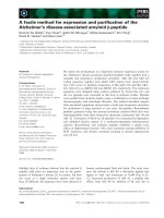
The numerical model for design and
constructive controlling of the excavation wall of
the Madison Building (Ho Chi Minh City) was
established basing on designed structures and
geological engineering conditions from TYLIN
International Viet Nam (2016). The Plaxis 2D
software environment for modeling with three
modules: (1) input, (2) calculations, (3) output
(Figure 1). The "input" module is used to set and
assign input data for the "calculation" module,
including geometric modeling, load assign,
boundary condition setting, and calculation phase
setting. The "calculation" module is used to
perform calculation processes according to the
Calibration
Displacement diagram
Loading
INPUT
Boundary condition
CALCULATION
Choose point and
calculate
Relational chart
Displacement values
Calculation phases
Figure 1. Steps and components of the excavation wall numerical model in the Plaxis 2D.
OUT
-PUT
Ha Viet Nhu and et al./Journal of Mining and Earth Sciences 61 (3), 19 - 27
actual constructive stages. The "result" module
uses the output of the "calculation" module for
displaying values, diagrams, graphs of relations
between stress and displacement. The numerical
was initially assigned a material model as MohrCoulomb (M-C model), then could be updated
with others as soft soil model, hard soil model, etc.
for calculation. Stress - deformation relationship
of these models is a combination of linear and
nonlinear behavior. They have good predictability
of displacement and failure for geotechnical
problems under different conditions.
21
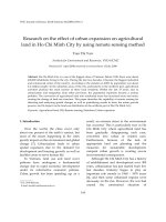
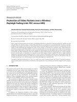
The geometric model was established
according to the designed excavation of 60.29 x
34.37 m, and it’s designed structure of the
excavation wall of 800 mm thick by reinforced
concrete (Figure 2).
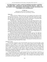
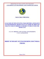
The excavation wall with a depth of 37.0 m is
designed as a retaining wall for the basement
(total of 3 basements and 12.9 m depth) (Figure
3). Excavation walls and posts were modeled as
structural elements. In that, the retaining walls
were modeled by as "plate" elements, and the post
system was modeled as "anchor" elements.
60,29 m
`
IL06
34,37 m
2
IL07
Reinforced concrete, 800mm
Excavation wall
2
1
1
1
1
2
IL04
2
IL02
Figure 2. Layout design of excavation wall of the Madison Building (TYLIN International Viet Nam 2016).
Excavation wall
- Reinforced concrete
- 800mm
Borehole
- BH1
+2,9m
+1,7m
+0,4m
1
2
3
-2,1m
Basement B1: -3,2m
Basement B2: -6,5m
Basement B3: -10,8m
37,0m
4
1
Filling soil
2
Sandy clay with gravel,
reddish-brown, medium stiff
3
Clay with silt, dark gray, very
soft
Fine-medium sand, yellowish
gray, medium dense
4
5
-31,6m
IL07
5
Clay, reddish-brown,
hard
Inclinometer observation
position
Figure 3. Typical sectional design of excavation wall and engineering geology condition of the Madison
Building (TYLIN International Viet Nam 2016).
22
Ha Viet Nhu and et al./Journal of Mining and Earth Sciences 61 (3), 19 - 27
Along with the depth of the excavation wall, a
total of 5 soil layers (based on the BH1 borehole)
were modeled, including: (1) filling soil, 1.2 m
thick; (2) sandy clay with gravel, reddish-brown,
medium stiff, 1.3 m thick; (3) clay with silk, dark
gray, very soft, 2.5 m thick; (4) fine-medium sand,
yellowish gray, medium dense, 29.5 m thick; and
(5) clay, reddish-brown, hard, unknown thickness
(UGEFEM 2015) (Figure 3).
Corresponding to the actual construction
phase, the calculation phase of the numerical
model was set up in three phases, such as: (1)
digging to the bottom of the B1 basement (the
bottom elevation -3.2 m ), (2) digging to the
bottom of B2 basement (bottom elevation -6.5 m),
and (3) digging to the bottom of the B3 basement
(bottom elevation -10.8 m) (Figure 3).
The mechanical parameters of the excavation
walls were assigned as Table 1, the horizontal
posts as Table 2. The designed load of 20 floors
building as 20.0 kN/m2, the road load as 10.0
kN/m2 and the sidewalk load as 5.0 kN/m2
according to the design documents of the
surrounding project (TYLIN International Viet
Nam 2016).
The typical properties of soil layers were
extracted from the engineering geological survey
report (UGEFEM 2015) that were assigned tin to
the numerical model of the Madison Building is
presented in Table 3.
The characteristics of the groundwater level
of the numerical model are determined according
to the monitoring data corresponding to the
actual constructive phases. At the time of digging
to the bottom of the B1 basement, the
groundwater level changes from -3.35 m (MW3)
to -4.60 m (MW4). In contrast, the groundwater
level changes from -3.20 m (MW3) to -10.20 m
(MW4) when digging to the bottom of the B2
basement and from -2.70 m (MW3) to -20.40 m
(MW6) when digging to the bottom of the B3
basement, respectively (Table 4).
Table 1. Mechanical parameters of the excavation wall system.
Poisson's
Mp;
Np;
Parameter Axial stiffness, EA; Bending stiffness, EI; Weight, w;
[kN/m]
[kNm²/m]
[kN/m/m] coefficient, ;[-] [kNm/m] [kN/m]
DW 800
2,160E+07
1,152E+06
4,8
0,20
1E15
1E15
Table 2. Mechanical parameters of horizontal posts.
Parameter
Axial stiffness, EA; [kN]
H400
3,321 E+6
Maximum compressive strength,
Interval, Lspacing; [m]
|Fmax, comp|; [kN]
1E+15
7,5
Table 3. Summary of parameters of soil layers.
Layer
Type
unsat
(kN/m3)
sat (kN/m3)
E50ref (kN/m3)
Eoedref (kN/m3)
Eurref (kN/m3)
m
c (kN/m2)
(o)
(o)
Rinter
1
Undrained
19,14
19,55
15000
15000
75000
0,55
0,2
5
25
0
0,5
2
Undrained
19,67
20
28200
28200
14100
0,8
0,2
12,1
20,8
0
0,8
3
Undrained
20,21
20,59
51000
51000
255000
0,7
0,2
35,5
22
0
0,95
4
Undrained
19,85
20,21
48750
48750
243750
0,8
0,2
23,8
23,2
0
0,95
5
Drained
20,17
20,68
100000
100000
500000
0,55
0,2
4,7
26,5
0
0,95
Ha Viet Nhu and et al./Journal of Mining and Earth Sciences 61 (3), 19 - 27
During the "calculation", the excavation wall
displacement results from the numerical model at
the position of inclinometer installation (Figure
2), which were compared with the monitoring
results to adjust the input parameters and
material model. Along with the process of
excavation wall construction, displacements of
the excavation wall and surrounding ground base
subsidence from the updated numerical models
provided the basis for design and constructive
controlling.
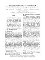
3. Results
The numerical model of the excavation wall
of the Madison Building was established that its
components, including designed excavation wall
and extended ground base structures modeled as
a combination of two digital cross-sections
perpendicular to excavation sides. After
calibrating based on data of inclinometer
deformation monitoring, the final material model
was assigned as Hardening Soil - HS model for
Phase
Period
Bottom B1
Bottom B2
Bottom B3
Ck24
Ck37
Ck78
23
calculation. The model has been calibrated input
parameters basing on actual displacement
monitoring data for all three construction/
calculation phases (Figure 4).
The analysis results of displacement of the
excavation wall when digging to the bottom of the
B1 basement from the numerical model showed
the maximum value of 11.84 mm (IL07 position),
13.03 mm (IL04 position), 11.55 mm (IL06
position), and 17.03 mm (IL02 position). The
amplitude of displacements is within the
allowable limit, according to British Standards
Institution (2015). These maximum displacement
values are all at the top of the excavation wall and
decrease with depth (Figure 5). Accordingly, the
analysis results of surrounding ground base
subsidence showed the maximum values of -7.16
mm (IL04 position at the 1-1 cross-section) and 9.35 mm (IL02 position at the 2-2 cross-section).
These maximum values are all located near the
outer edge and decline when they are away from
the excavation wall (Figure 6).
Table 4. Summary of groundwater parameters.
Observation well
MW1 (m)
MW3 (m)
MW4 (m)
-3,50
-3,35
-4,60
-3,45
-3,20
-10,20
-2,85
-2,70
-19,55
MW6 (m)
-4,40
-9,60
-20,40
Figure 4. Calibration results of a numerical model based on excavation wall displacement values.
24
Ha Viet Nhu and et al./Journal of Mining and Earth Sciences 61 (3), 19 - 27
The analysis results of displacement of the
excavation wall when digging to the bottom of the
B2 basement from the numerical model showed
the maximum value of 11.52 mm (IL07 position),
13.91 mm (IL04 position), 11.35 mm (IL06
position), and 16.82 mm (IL02 position). The
displacement increases at a depth of the B2
basement depth, but the highest values are still at
the top of the excavation wall and decline in depth
(Figure 7). The amplitude of displacements is
within the allowable limit, according to British
Standards Institution (2015). Accordingly, the
analysis results of the maximum surrounding
ground base subsidence reached values of -8.84
mm (IL04 position at the 1-1 cross-section) and 11.13 mm (IL02 position at the 2-2 cross-section).
These maximum values are all located near the
outer edge and decline when being away from the
excavation wall (Figure 8)
Depth (m)
Displacement (mm)
Figure 5. Displacement of the excavation wall of the basement in B1 phase at the 1-1 cross-section (IL07 and
IL04) and the 2-2 cross-section (IL06 and IL02).
Distance (m)
Subsidence (mm)
Excavation wall
Excavation wall
Excavation wall
Excavation wall
Figure 6. Surrounding ground base subsidence of the excavation wall in B1 phase at the 1-1 cross-section
(IL07 and IL04) and the 2-2 cross-section (IL06 and IL02).
Ha Viet Nhu and et al./Journal of Mining and Earth Sciences 61 (3), 19 - 27
25
Depth (m)
Displacement (mm)
Figure 7. Displacement of the excavation wall in the constructive in B2 phase at the 1-1 cross-section
(IL07 and IL04) and the 2-2 cross-section (IL06 and IL02).
Distance (m)
Subsidence (mm)
Excavation wall
Excavation wall
Excavation wall
Excavation wall
Figure 8. Surrounding ground base subsidence of the excavation wall in B2 phase at the 1-1 cross-section
(IL07 and IL04) and the 2-2 cross-section (IL06 and IL02.
Displacement (mm)
IL07
IL04
IL06
IL02
Figure
Displacement
of the
excavation
of the basement
in B3 phase
at the
1-1cross-section (IL07
Figure 9. Displacement
of1.the
excavation
wall
of the wall
basement
in B3 phase
at the
1-1
and IL04) and the 2-2 cross-section (IL06 and IL02).
26
Ha Viet Nhu and et al./Journal of Mining and Earth Sciences 61 (3), 19 - 27
Distance (m)
Subsidence (mm)
Excavation wall
Excavation wall
Excavation wall
Excavation wall
Figure 10. Surrounding ground base subsidence of the excavation wall in B3 phase at the 1-1 cross-section
(IL07 and IL04) and the 2-2 cross-section (IL06 and IL02).
The analysis results of displacement of the
excavation wall when digging to the bottom of the
B1 basement from the numerical model showed
the maximum value of 29.11 mm (IL07 position),
29.52 mm (IL04 position), 37.50 mm (IL06
position), and 37.87 mm (IL02 position).
However, these maximum displacement values
are not at the top of the excavation wall but at the
bottom of the B3 basement (Figure 9). The
amplitude of displacements is within the
allowable limit, according to British Standards
Institution (2015). Accordingly, the analysis
results of surrounding ground base subsidence
from it showed the maximum values of -28.32 mm
(IL04 position at the 1-1 cross-section) and -23.74
mm (IL02 position at the 2-2 cross-section). The
maximum values are located about 10.0 m from
the outer edge of the excavation wall and decrease
when being away from the excavation wall
(Figure 10).
4. Conclusions and discussions
The numerical model has been established
and calibrated using the finite element method on
Plaxis 2D software that allowed well control of the
design and construction processes of the Madison
Building basement. The model covers all
structural elements and complex engineering
geology conditions.
Displacements of the excavation wall and
surrounding ground base subsidence were
analyzed corresponding to the constructive
phases of three basements. The results showed
that the displacement of the excavation wall at all
positions increase rapidly when constructing the
B1 basement because of delaying in construction
of the sport system. All values are within
allowable limits, according to British Standards
Institution (2015), the maximum displacement
values are at the top and decrease in depth of the
excavation wall. At the B2 basement constructive
phase, the maximum displacement of the
excavation wall at all locations (except for IL04)
was decreasing due to the sport system which had
been completed that makes a balance with the
earth pressure. Overall, all maximum
displacement values remain at the top of the
excavation wall and within the limits of
deformation, according to British Standards
Institution (2015). When digging to the bottom of
the B3 basement, all values of the excavation wall
displacement were increasing. The maximum
increase is along the long side of the excavation
wall (IL02 and IL06 positions) and less along the
short side (IL04 and IL07 positions). At this phase,
the excavation wall tends to be bending
deformation with upper and lower ends fixed and
balanced by horizontal pressure by the sports and
Ha Viet Nhu and et al./Journal of Mining and Earth Sciences 61 (3), 19 - 27
deep ground base. The middle part had the
displacement (maximum) with more than double
the value of the maximum displacements in
phases of the digging to the bottom of the B1 and
B2 basements; located in the deeper area which is
adjacent to the bottom of the excavation.
However, all displacement values were within the
allowable limits.
The surrounding ground base subsiding is
associated with the displacing of the excavation
wall. This subsidence increases according to
digging stages, from B1 to B3. At locations that are
adjacent to the excavation wall, due to the friction
between the soil and the wall, the subsidence
values were not maximum. That values were
located from 1÷3 m to the excavation wall and
gradually decreased with the distance to it. In the
excavation stage of the B3 basement, the wall
tends to bend deformation, and the displacement
rapidly increased to a maximum at the bottom of
the excavation. Accordingly, the subsidence also
rapidly increased to the previous two phases and
reached a maximum at the location about 10 m
from the wall.
In general, the analysis results of the
numerical model were consistent with the actual
construction process that is useful for design and
constructive controlling of the excavation wall.
However, because it only modeled as a
combination
of
digital
cross-sections
perpendicular to excavation sides, it had not been
able to model the fullest working conditions. In
the future, it could be upgraded in advance with
3D finite element methods.
5. Acknowledgment
We would like to express our thanks to Bac
Nam 79 Construction Joint Stock Company 79,
NQH Architects Company, TYLIN International
Vietnam Company, and the Union of Geoscience Foundations - Building Materials for providing
data for this study.
27
References
British Standards Institution, 2015. BS 8002:2015
Code of practice for earth retaining structures
Chau Ngoc An, Le Van Pha, 2007. Calculation of
structure to protect deep foundation pit by the
method of considering the simultaneous
working between the ground and the
structure. Journal of Science and Technology
Development 10.
Helmut F. Schweiger, 2007. Modelling issues for
numerical analysis of deep excavations.
Institute for Soil Mechanics und Foundation
Engineering Graz University of Technology,
Austria.
Krasinski, A., Urban, M., 2011. The results of
analysis of deep excavation walls using two
different methods of calculation. Archives of
Civil Engineering. 59-72. Versita, Warsaw.
Kung, G., E. Hsiao and C. J. C. G. J. Juang, 2007.
Evaluation of a simplified small strain soil
model for predicting excavation-induced wall
deflection and ground movement.
Ngo Duc Trung, Vo Phan, 2011. Analyzing the
influence of ground model on displacement
prediction and deformation of deep
excavations stabilized by retaining walls.
Proceedings of the 12th Scientific and
Technological Conference, Faculty of Civil
Engineering. Ho Chi Minh City University of
Technology.
Plaxis, C. T., (2011). Plaxis 2D v8.2.
Terzaghi, K., Peck, R. B. and Mesri, G., 1996. Soil
Mechanics in Engineering Practice, John Wiley
& Sons.
TYLIN International Viet Nam, 2016. Construction
drawing of Excavation Wall - Madison
Complex Building.
UGEFEM,
2015.
Engineering
Geological
Investigation Report of Madison project at 15
Thi Sach, Ben Nghe district, 1 ward, Ho Chi
Minh city.