Effect of nitrogen precursors on lithium storage behavior of nitrogen doped-ordered mesoporous carbon
Bạn đang xem bản rút gọn của tài liệu. Xem và tải ngay bản đầy đủ của tài liệu tại đây (946.94 KB, 6 trang )
Journal of Science & Technology 142 (2020) 017-022
Effect of Nitrogen Precursors on Lithium Storage Behavior of Nitrogen
Doped-Ordered Mesoporous Carbon
Le Thi Thu Hang
Hanoi University of Science and Technology – No. 1, Dai Co Viet Str., Hai Ba Trung, Ha Noi, Viet Nam
Received: August 10, 2018; Accepted: June 22, 2020
Abstract
Ordered mesoporous carbon (CMK3) before and after doping with nitrogen (N) are prepared successfully by
a nanocasting method using sucrose as carbon source, and urea (or melamine) as nitrogen source. After
doping N, the materials show an increase in the specific surface area and a slight decrease in the porosity.
The N content of the N-doped CMK3 obtained from melamine precursor (CMK3-M) is 5.82 at.%, approximately
4 times as high as that of the N-doped CMK3 obtained from urea precursor (CMK3-U). Among three resultant
samples, the CMK3-M exhibits the highest lithium storage capability. Owing to possessing the high N content
the CMK3-M can deliver a reversible capacity of 812.7 mAh/g at a current density of 100 mA/g. After 50 cycles
of the charge-discharge, the CMK3-M deliveries the capacity of 652.06 mAh/g, maintaining 80.2% of its initial
reversible capacity with a high coulombic efficiency of 99.5%.
Keywords: Mesoporous carbon, lithium storage, nanocasting
1. Introduction*
Moreover, since the lithium storage mechanism of
non-graphitic carbon is somewhat different from that
of graphite, these materials show much higher.
Particularly, in addition to Li+ intercalation/deintercalation mechanism in carbon layers, the nongraphitic
carbon
materials
exhibit
lithium
adsorption/desorption mechanism on the surface sites
of the domain boundary or the grain boundary sites or
in nanopores, and cavities [3]. Hence, the surface area
and pore size of the carbon materials play an important
role in controlling their specific capacity. Besides,
chemical doping can be considered as an effective
strategy to tailor the electronic and crystalline
structures of the carbon materials, enhancing their
chemical stability, surface polarity, electric
conductivity, and electron-donor properties of nongraphitic carbon. Hence, it has a great impact on LIBs
application [4]. Recently, extensive investigations
have reported that nitrogen (N) doping can increase the
electronic conductivity and rate of electron transfer of
carbon materials, for example, carbon nanotube [5],
graphene [6], as well as generate more active sites for
lithium ion storage.
Lithium-ion batteries (LIBs) have been widely
used as the power supply of various applications from
consumer electronics, transportation vehicles to
military apparatus, thanks to their advantages such as
superior high energy and power densities, long
lifespan, and low self-discharge rate [1]. Especially,
the past decade has seen a growing trend towards nextgeneration LIBs with high charge capacities/power
densities developed for electric vehicles, hybrid
electric vehicles, aerospace applications, and
autonomous
electric
devices.
Meanwhile,
conventional LIBs, which are mainly based on Li+
intercalation/de-intercalation mechanism, have almost
reached their limit. This stems from the theoretical
capacity of both anode and cathode materials.
Currently, graphite with a theoretical specific
capacity of 372 mAh/g has been used as main anode
material for LIBs. This specific capacity value seems
to be insufficient to meet the increasing energy
demand for batteries with higher energy densities,
power densities, and rate capabilities [2]. Thus,
development of advanced materials having higher
reversible capacity, rate capabilities, long-term
cyclability and low cost to alter graphite anodes is
required. Among them, carbonaceous materials,
especially non-graphitic carbon, have emerged as
promising alternatives to replace graphite anode for
LIBs due to their high electrical conductivity, good
hierarchical structure, abundance, and low cost.
Since reported in 2001 by Ryoo and workers [7],
ordered mesoporous carbon (OMC) materials have
been received significant attention owing to their
excellent textural characteristics and mesoporous
network. This structure provides a highly opened 3D
porous host with easy access for guest species, thus
facilitating diffusion throughout the pore channels
*
Corresponding author: Tel.: (+84) 973469466
Email:
17
Journal of Science & Technology 142 (2020) 017-022
without pore blockage [4]. The outstanding features
allow them to be ideal candidates for active materials
of LIBs. N-doping into OMCs could be implemented
via three methods as follows: (i) post heat-treatment
[8], (ii) chemical treatment [9], and (iii) direct
pyrolysis of the N-containing precursors [10]. Among
them, only the final method enables gaining a
relatively large amount of nitrogen in doped-OMCs,
thereby changing the properties of the bulk carbon
backbones, particularly the conductivity.
mL of another aqueous solution containing sucrose
(3.2 g), 6.2 g urea (or melamine) and H2SO4 (0.36 g)
and followed by a drying process at 100 oC for 12 h.
Subsequently, SBA-15 filled by sucrose was
carbonized at 900 °C for 5 h in an argon atmosphere to
generate the composites of SBA-15 and carbon. To
remove the SBA-15 template, SBA-15/carbon
composite was soaked in 5 wt% HF solution for 48 h.
Finally, the products including CMK3, CMK3-U and
CMK3-M were centrifuged, washed, and dried at 100
°C under vacuum overnight.
This study reports investigation on the effect of
N-containing precursors including urea and melamine
on the morphological, structural and physicochemical
properties as well as lithium storage behavior of OMC
material, namely CMK-3, which serves as anode
active material for LIBs.
2.2. Characterization of morphology, structure and
physicochemical properties
The morphology and structure features of the
materials were characterized using a field emission
scanning electron microscope (SEM, S-4700/EX-200,
Hitachi, Japan), a high-resolution X-ray diffractometer
(XRD, D/MAX Ultima III, Rigaku, Japan), a X-ray
photoelectron spectroscopy instrument (XPS, Multilab
2000, VG, UK), Raman spectrometer (Horiba JobinYvon), and Brunauer-Emmett-Teller (BET) analysis
(ASAP 2020, Micromeritics, USA).
2.3. Electrochemical characterization
To investigate electrochemical properties of the
resultant carbon samples, CR 2032-coin cells were
assembled in an argon-filled glove box. A cell was
composed of a working electrode, a metallic Li
electrode and a glass fiber separator soaked with 100
µL of 1 M LiPF6 in ethylene carbonate (EC), dimethyl
carbonate (DMC) (1:1, by volume), and 5 wt%
fluoride ethylene carbonate (FEC) as additive.
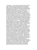
Fig. 1. Schematic diagram of Schematic diagram of
synthesis process of N-doped CMK3.
The working electrode was prepared by mixing
well a mixture of 40 mg of CMK3 (or CMK3-U or
CMK3-M), 5 mg of super-P carbon, and 5 mg of
Polyvinylidene fluoride (PVDF) binder in N-Methyl
pyrrolidone (NMP) solvent, then casting on a Cu foil
as current collector. After drying in a vacuum oven at
120 ℃ for 24 h, the foil was punched into 14 mm
diameter-disks.
2. Experimental
2.1. Preparation of ordered mesoporous carbon
Ordered short-rod silica particles (SBA-15) were
synthesized via the previously reported process [11,
12]. Ordered mesoporous carbon materials, CMK3,
before and after doping nitrogen were prepared by a
nano-casting method using SBA-15 as hard template,
sucrose as a carbon source [12], urea and melamine as
nitrogen source. The CMK3 sample doped nitrogen by
using urea precursor is denoted as CMK3-U and the
sample prepared from melamine precursor is referred
to CMK3-M. The synthesis process is illustrated in
Figure 1. In detail, 4 g of SBA-15 was dispersed in an
aqueous solution containing 5 g of sucrose, 10 g urea
(or melamine) and 0.56 g H2SO4 and then mixed well
for 30 mins in an ultrasonic bath. Next, the mixture
was dried in an oven at 100 °C for 6 h and at 160 °C
for another 12 h.
Cyclic voltammogram (CV) measurements were
carried out using Gamry PC750 potentiostat. The cells
were discharged and charged at the potential range of
0.01- 3.0 V vs. Li+/Li using an automatic battery cycler
(WonATech-WBCS 3000).
3. Results and discussion
3.1. Morphology and physicochemical properties
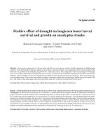
Figure 2 present the SEM and TEM images of the
synthesized CMK3 materials. For comparison, the
SEM and TEM images of SBA-15 template was
included. As shown in the low-resolution SEM images
(Figures 2a-d), all the synthesized materials including
CMK3, CMK3-U and CMK3-M show the same
After treatment in the oven, the obtained dark
brown sample was ground prior to re-dispersal in 20
18
Journal of Science & Technology 142 (2020) 017-022
morphology with that of SBA-15, which was the hard
template to create them. These samples were
composed of uniform chrysalis-like-short nanorod
particles with ~1µm in length and ~500 nm in
diameter. However, the size of the chrysalis-like
particles of the obtained carbon samples seems to be
smaller than that of the SBA-15 template. It can be
explained that SBA-15 was the hard template, which
was used to fill carbon inside. After removal of the
outer shell of the SBA-15 template, the three
dimensional (3D) structure of carbon samples were
released. This resulted in the smaller size of casted
carbon compared with the initial SBA-15 template.
Additionally, it is found that after doping N, the
morphology of both CMK3-U and CMK3-M samples
hardly changed in comparison with CMK3 sample
before doping. The nanorods were still interconnected
together to form a porous structure. Noticeably, the
geometrically structural collapse phenomenon was not
observed. Hence, from the low-resolution SEM
images, the difference between the morphology of the
SBA-15 template and those of the CMK3 carbon
materials is hardly identified. In contrast, it is totally
clear for observation from the high-resolution SEM
and TEM images (Figures 2e-h). Herein, the ordered
arrangement of CMK-3 carbon was obviously inferior
to its initial template. In addition, more pores left after
removal of the SBA-15 template by HF acid were
found on the surface of CMK3 nanorods as well.
To confirm whether the structural collapse
phenomenon happen inside the nanorods or not, the
low angle XRD analysis was conducted within 2 =
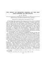
0.5-3.0 °. As shown in Figure 3a, obviously after
etching the SBA-15 template, the sharp diffraction
peak of the carbon samples was retained despite a
slight shift toward the high diffraction angle. This
indicates the integrity of the ordered mesoporous
structure of the synthesized carbon samples, which is
in high agreement with the previous reports [8, 9].
From the wide angle XRD analysis in Figure 3b, it is
recognized that XRD pattern of the carbon samples is
quite different from that of the SBA-15 template,
which only possesses a broad peak representing
amorphous structure. All the CMK3, CMK3-U and
CMK3-M samples exhibit two broad diffraction peaks
at 2 = 24o and 2 = 44o. These peaks correspond to
the (002) and (100) diffraction indexes for disordered
carbon phase and graphitized carbon, respectively
[13], indicating their nature of turbostratic carbon
structure.
Table 1. Physicochemical analysis data of the
synthesized carbon samples.
Parameters
C (at.%)
O (at.%)
N (at.%)
SBET (m2/g)
dp (nm)
Vp (cm3/g)
CMK3
CMK3-U
CMK3-M
94.72
5.28
1049
4.16
1.09
92.38
6.16
1.46
1124
3.72
1.05
85.71
8.47
5.82
1091
3.87
1.06
To verify further the carbon structure of the
synthesized samples, their Raman spectra were
recorded. Figure 3c depicts Raman spectra of the
CMK3, CMK3-U and CMK3-M samples between 400
and 4000 cm-1. As seen, both D band around 1338
cm-1 and G band around 1590 cm-1 are present in the
Raman spectra of these samples. The D band is related
to structural defects and partially disordered structures
of the sp2 domains while the G band is associated to the
E2g vibration mode of graphitic sp2 carbon domains.
This again proves the turbostratic structure of the
synthesized carbon samples.
Fig. 2. SEM images of (a,e) SBA-15 template, (b,f) CMK3, (c) CMK3-U and (d) CMK3-M; TEM images of (g)
SBA-15 and (h) CMK3.
19
Journal of Science & Technology 142 (2020) 017-022
Fig. 3. (a) Low and (b) wide angle XRD, (c) Raman spectra, (d) XPS survey spectra, (e) N2 adsorption/desorption
isotherms, and (f) pore distribution plot of CMK3, CMK3-U and CMK3-M.
XPS is a powerful technique for the
characterization of elemental composition and
bonding configuration in materials. Figure 3d is XPS
survey spectra of the carbon samples. For the XPS
spectra of CMK3-U and CMK3-M, the typical peaks
of C 1s, O 1s and N 1s were found. In contrast, only
two peaks of C 1s and O 1s were detected in the XPS
spectrum of CMK3. The presence of N 1s peaks in the
CMK3-U and CMK3-M demonstrates the successful
incorporation of N in the carbon network of these
materials. Their detailed C, O and N contents are listed
in Table 1. It can be seen that despite the same mass of
the used nitrogen precursors, CMK3-U reveals a lower
N content (1.46 at.%) than that of CMK3-M (5.82
at.%). Remarkably, CMK3-M also has a high O
content of 8.47 at% compared with CMK3-U (6.16
at.%), and CMK3 (5.28 at.%). Oxygen is also
considered as doped heteroatom and may play as a
positive role for lithium storage by increasing defects,
disorder, or local electron density around O atoms.
Thus, it might offer additional benefit for the CMK3M material. These XPS results suggest that CMK3-M
synthesized from melamine precursor would possess
more favorable modified carbon network structure for
lithium storage.
before doping N the specific surface area (SBET) of
CMK3 was 1049 m2/g. After doping N, the specific
surface area of both CMK3-U and CMK3-M increased
up to 1124 m2/g and 1091 m2/g, respectively. This is
ascribed to the activation of carbon from NH3 which
was generated from decomposition of urea and
melamine during the carbonization process of CMK3U and CMK3-M. Meanwhile, their mean pore size (dp)
and total pore volume tended to decrease. However,
these changes are negligible.
3.2. Electrochemical properties
From Figure 3e-f, all N2 adsorption-desorption
isotherms of CMK3, CMK3-U and CMK3-M
apparently show a typical hysteresis loop for
mesoporous structure materials. This demonstrates
that the synthesized CMK3 samples were ordered
mesoporous carbon. The textural parameters of these
materials are enumerated in Table 1. It is observed that
Fig. 4. Cyclic voltammograms of CMK3, CMK3-U
and CMK3-M electrodes at a scan rate of 0.1 mV/s for
first three cycles.
20
Journal of Science & Technology 142 (2020) 017-022
To clarify lithium storage mechanism of the
CMK3 samples before and after doping N, cyclic
voltammetry (CV) measurements were conducted
within a potential range from 0.01 to 3.0 V (vs.
Li+/Li) at a scan rate of 0.1 mV/s with open circuit
voltage as initial potential point. Figure 4 shows the
CV plots of the CMK3, CMK3-U and CMK3-M
electrodes for first three cycles. The CV plots of all
electrodes reveal more charge consumption for the
reduction process rather than the oxidation process at
the first cycle. Moreover, several main cathodic peaks,
for example, a peak at ~ 0.6 V or a peak at 1.6 V, only
appeared at this first cycle. From the second cycle
onwards, these cathodic peaks totally disappeared,
implying the irreversible formation of solid electrolyte
interphase (SEI) layer on the surface of the electrodes
for the first cycle. In addition, the intensity of these
cathodic peaks was found to be higher for the N-doped
samples.
This
implies
that
the
surface
functionalization of CMK3-U, and CMK3-M caused
by doping N into carbon network promoted the
formation of the SEI layer. Also, from the second cycle
onwards, the lithium storage process was almost
recorded at the potential below 0.45 V, which is
contributed by under potential deposition of lithium
metal [14]. Another small part contribution to
discharge capacity of the electrode came from lithium
storage in manifold defects of 3D architectures, pores,
cavities, boundaries between differently oriented
graphite crystallites in turbostratic carbon, as well as
Li binding with heteroatoms [15]. This lithium storage
process occurred at the potential above 0.45 V.
of the anode materials, respectively [16-18]. After
doping N, both CMK3-U and CMK3-M electrodes
showed the higher intensity of the anodic peak at 1.18
and 2.4 V than that of the CMK3 electrode. This
resulted in much contribution to the reversible capacity
of the electrodes owing to the presence of the
heteroatoms in the carbon network.
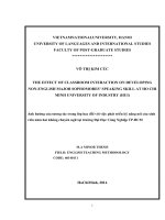
To elucidate the cyclability of the N-doped
CMK3 materials, the electrodes were cycled between
the potential from 0.01 V to 3.0 V (vs. Li+/Li). Figure
5 illustrates the cycling performance of the CMK3-U
and CMK3-M at a current density of 100 mA/g for 50
cycles. As seen in Figure 5a, at the first cycle, the
CMK3-M electrode delivered the discharge and charge
capacities of 1847.4 and 467.7 mAh/g, respectively.
Meanwhile, the CMK3-U and CMK3 electrode only
delivered the discharge/charge capacities of
1812.3/762.3 mAh/g and 1576.8/776.6 mAh/g,
respectively. The achieved higher capacity of the
CMK3-M electrode is attributed to the high content of
N heteroatom dopant, which improved electric
conductivity [4] as well as generated more defect sites
for lithium storage. It is worthy seeing that among
three electrodes the CMK3-U electrode revealed the
lowest initial coulombic efficiency of 42.1% (Figure
5b). Meanwhile, the rest electrodes showed higher
values, 49.3% for CMK3 electrode and 46.9% for
CMK3-M electrode. This is due to the highest specific
capacity and smallest mean pore size of CMK3-U.
Accordingly, the amount of lithium loss caused by
formation of irreversible SEI layer and by difficulty in
lithium extraction from cavities for the CMK3-U was
larger. After 10 cycles of discharge and charge, the
previously formed SEI layer became stable. Hence, the
specific capacity of the electrodes almost remained
stable. After 50 cycles, the CMK3-M could deliver a
charge capacity (a reversible capacity) of 652.1
mAh/g, corresponding to a retention of 75% of the
initial charge capacity with a coulombic efficiency of
99.5 %. At the same time, the CMK3 and CMK3-U
For the anodic scan direction, lithium extraction
happened within wide potential from 0.01 to 3.0V. It
is noted that three weak anodic peaks was observed
at
around 0.14, 1.18 and 2.4 V. These peaks
correspond to lithium extraction from graphite-like
nano sized carbon domains,
from pore
structure/defective sites and from binding with
heteroatoms, viz. N atom and O atom, on the surface
Fig. 5. (a) Discharge-charge capacities and (b) coulombic efficiency of CMK3, CMK3-U and CMK3-M electrodes
for 50 cycles at a C-rate of 0.1C.
21
Journal of Science & Technology 142 (2020) 017-022
[8]. J. Przepiórski, Journal of Hazardous Materials, 135
(2006) 453-456.
electrodes only delivered a lower reversible capacity
of 461.5 mAh/g, and 519.1 mAh/g, respectively. Both
these electrodes after 50 cycles showed coulombic
efficiencies of 98.2% and 98.6%, which is a little bit
lower than that of the CMK3-M electrode.
[9]. V.C. Almeida, R. Silva, M. Acerce, O.P. Junior, A.L.
Cazetta, A.C. Martins, X. Huang, M. Chhowalla, T.
Asefa, Journal of Materials Chemistry A, 2 (2014)
15181-15190.
In brief, the electrodes of CMK3 before and after
doping N showed the much higher reversible capacity
than that of a commercial graphite anode, with the high
coulombic efficiency of > 98%. This proves high
potential application of both undoped and N-doped
CMK3 as anode active material for LIBs.
[10]. Z. Qiang, Y. Xia, X. Xia, B.D. Vogt, Chemistry of
Materials, 29 (2017) 10178-10186.
[11]. D. Zhao, J. Feng, Q. Huo, N. Melosh, G.H.
Fredrickson, B.F. Chmelka, G.D. Stucky, Science, 279
(1998) 548.
[12]. X. Ji, K.T. Lee, L.F. Nazar, Nature Materials, 8 (2009)
500.
4. Conclusion
N-doped CMK3 materials with 3D connected
ordered mesoporosity and extremely high specific
surface area (> 1000 m2/g) have been sucessfully
synthesized by using ordered mesoporous silica as
hard-template, sucrose as carbon source and urea as
well as melamine as nitrogen source. After doping N,
CMK3-M showed the most excellent lithium storage
performance for LIBs anode material application with
unchanged lithium storage mechanism in comparison
with CMK3 mother material. Owing to introducing the
N heteroatomic elements into their carbon network, the
surface of the materials was modified. The number of
defect sites was increased. Besides, the electrical
conductivity could be increased. Accordingly, the
lithium storage performance of the N-doped CMK3
materials were improved significantly.
[13]. G. Tao, L. Zhang, L. Chen, X. Cui, Z. Hua, M. Wang,
J. Wang, Y. Chen, J. Shi, Carbon, 86 (2015) 108-117.
[14]. J.R. Dahn, T. Zheng, Y. Liu, J.S. Xue, Science, 270
(1995) 590.
[15]. J. Hou, C. Cao, F. Idrees, X. Ma, ACS Nano, 9 (2015)
2556-2564.
[16]. F. Su, C.K. Poh, J.S. Chen, G. Xu, D. Wang, Q. Li, J.
Lin, X.W. Lou, Energy & Environmental Science, 4
(2011) 717-724.
[17]. B. Guo, X. Wang, P.F. Fulvio, M. Chi, S.M. Mahurin,
X.-G. Sun, S. Dai, Advanced Materials, 23 (2011)
4661-4666.
[18]. M. Endo, C. Kim, K. Nishimura, T. Fujino, K.
Miyashita, Carbon, 38 (2000) 183-197.
Acknowledgements
This research was financially supported by the
Vietnam Ministry of Education and Training (MOET)
through the project with the code B2018-BKA-62.
References
[1]. T. Kim, W. Song, D.-Y. Son, L.K. Ono, Y. Qi, Journal
of Materials Chemistry A, 7 (2019) 2942-2964.
[2]. A. Manthiram, J.C. Knight, S.-T. Myung, S.-M. Oh,
Y.-K. Sun, Advanced Energy Materials, 6 (2016)
1501010.
[3]. M. Winter, J.O. Besenhard, M.E. Spahr, P. Novák,
Advanced Materials, 10 (1998) 725-763.
[4]. H. Chen, F. Sun, J. Wang, W. Li, W. Qiao, L. Ling, D.
Long, Journal of Physical Chemistry C, 117 (2013)
8318-8328.
[5]. W.H. Shin, H.M. Jeong, B.G. Kim, J.K. Kang, J.W.
Choi, Nano Letters, 12 (2012) 2283-2288.
[6]. H. Xu, L. Ma, Z. Jin, Journal of Energy Chemistry, 27
(2018) 146-160.
[7]. R. Ryoo, S.H. Joo, M. Kruk, M. Jaroniec, Advanced
Materials, 13 (2001) 677-681.
22