A coded MIMO-OFDM system’s performance comparison of the spatial channel model and the onering channel model based on interpolation techniques
Bạn đang xem bản rút gọn của tài liệu. Xem và tải ngay bản đầy đủ của tài liệu tại đây (549.87 KB, 6 trang )
Journal of Science & Technology 139 (2019) 031-036
A Coded MIMO-OFDM System’s Performance Comparison of the Spatial
Channel Model and the Onering Channel Model Based on Interpolation
Techniques
1
Nguyen Thu Nga1*, Van Duc Nguyen1, Phuong Nam Ta1, Tran Quoc Toan2
Hanoi University of Science and Technology, No. 1, Dai Co Viet, Hai Ba Trung, Hanoi, Viet Nam
2
Viet Nam Atomic Energy Institute, No. 59, Ly Thuong Kiet, Hoan Kiem, Hanoi, Viet Nam
Received: April 15, 2019; Accepted: November 28, 2019
Abstract
In this paper, we consider to estimate the channel coefficient in the wideband and frequency selective multiinput multi-output orthogonal frequency division multiplexing (MIMO-OFDM) system. The simulation is based
on two channel models, one has been proposed by the 3rd Generation Partnership Project (3GPP) standard
- the Spatial Channel Model (SCM) and the other is the Onering channel model, under the LTE Advanced
standard for 4G in the suburban macro-cell environment. The obtained results show the symbol error rate
(SER) value when using different interpolations (Linear, Sinc or Wiener) with the same input parameters. The
Space Frequency Block Coding (SFBC) and minimum mean-squared error (MMSE) equalizer are also used
for the simulation of the MIMO 2x2 systems. The SER results in the SCM channel model are lower than that
obtained by the Onering channel model when employing the different interpolation methods.
Keywords: MIMO-OFDM, Onering channel model, SCM channel model, SFBC, Wiener interpolation, Sinc
interpolation, Linear interpolation
1. Introduction *
measurement. Therefore, there is huge database for
simulating those channel models.
Channel modelling method is used in the
wideband channel model to design and optimize the
communication systems. In the stochastic channel
model, we use the measurement results to simulate to
the statistical features from which are reproduced the
channel's probability properties. The geometry‐based
stochastic models (GBSM) and the parametric
stochastic models (PSM) are in the group of stochastic
channel model [1].
Based on the PSM channel model method, the
Third Generation Partnership (3GPP) develops the
spatial channel model (SCM) [3]. The SCM has been
studied for non-line of sight (NLOS) model for
suburban macro, urban macro and urban micro cell.
Authors in [4] have compared the spatial
correlation properties of both the SCM and the
Onering channel model in suburban macro cell.
Coding method SFBC which takes advantages of
diversity in frequency selective channel transmission
scheme and the equalizer MMSE [5] are combined to
investigate the performance of the MIMO-OFDMA
system in physic and medium access control (MAC)
layer.
In the GBSM, the assumptions are given that the
scatters are arranged in a geometrical form by using
the physical principles of reflections, scattering, and
diffractions of electromagnetic waves. The scatter’s
statistical properties are described by the distribution
of angle of arrival (AoA) and the angle of departure
(AoD). The Onering channel model of GBSM has
been shown for wideband and frequency selective
channel model in the Fourth Generation Advanced
Long Term Evolution (4G- LTE-A) in [2].
By reducing the pilot overhead requirements, the
interpolation algorithms are applied to the MIMOOFDM receiver to estimate the coefficient of the
channel. The interpolation techniques in [6]–[12] are
based on the training sequence estimation or the pilot
estimation.
In the PSM, the transmission paths which divide
into the sub‐paths of the paths, the AoA or AoD are
narrated by the channel parameters in the
Corresponding author: Tel.: (+84) 989145909
Email:
*
31
Journal of Science & Technology 139 (2019) 031-036
In this paper, we study the performance of the
symbol error rate (SER) when using different
interpolation methods (Linear, SI and Wiener) on
those channel models in 2×2 MIMO-OFDM system.
The channel models are simulated by using the SCM
channel model as well as the Onering channel model
under the LTE-A standard in NLOS case. We also
combine the SFBC and the MMSE detection to
improve the effectiveness of the channel estimation.
the transmit antenna at the BS and of the receive
antenna at the MS, respectively.
𝑂𝑂𝑂𝑂 (𝜏𝜏,
𝑡𝑡)
ℎ𝑢𝑢,𝑠𝑠
ℒ
=�
�𝑁𝑁𝑙𝑙
𝑙𝑙=1
where:
𝑑𝑑𝑢𝑢
Φ
Φ
BS
m ax
𝐼𝐼1
𝐼𝐼1
D
𝜑𝜑1
−𝜑𝜑1
Φ nM S
𝑀𝑀𝑀𝑀
cos�𝜙𝜙𝑛𝑛,𝑙𝑙
−𝛼𝛼𝑀𝑀𝑀𝑀 �,
𝑀𝑀𝑀𝑀
) sin�𝜙𝜙𝑛𝑛,𝑙𝑙
��,
(1)
Authors in [4] divide the scatter ring to ℒ pairs of
segments 𝐼𝐼𝑙𝑙 (𝑙𝑙 = 1 … . ℒ), each pair is considered as a
cluster of scatters. The 𝑙𝑙 𝑡𝑡ℎ pair (𝑙𝑙 = 1 … . ℒ) consists
of 𝑁𝑁𝑙𝑙 scatters, 𝑐𝑐𝑙𝑙 is the attenuation factor of the 𝑙𝑙 𝑡𝑡ℎ
𝑂𝑂𝑂𝑂 (𝑓𝑓,
𝑡𝑡) is a
path. The channel transfer function 𝐻𝐻𝑢𝑢,𝑠𝑠
𝑂𝑂𝑂𝑂 (𝜏𝜏,
Fourier transform of ℎ𝑢𝑢,𝑠𝑠 𝑡𝑡) as follows:
𝑂𝑂𝑂𝑂 (𝑓𝑓,
𝐻𝐻𝑢𝑢,𝑠𝑠
𝑡𝑡)
ℒ
𝑐𝑐𝑙𝑙
𝑁𝑁𝑙𝑙
(2)
� 𝑎𝑎𝑛𝑛,𝑠𝑠,𝑙𝑙 𝑏𝑏𝑛𝑛,𝑢𝑢,𝑙𝑙 × 𝑒𝑒 𝑗𝑗�2𝜋𝜋(𝑓𝑓𝑛𝑛,𝑙𝑙 𝑡𝑡−𝜏𝜏𝑙𝑙 𝑓𝑓)+𝜃𝜃𝑛𝑛,𝑙𝑙 )� .
𝑁𝑁
𝑙𝑙=1 � 𝑙𝑙 𝑛𝑛=1
=�
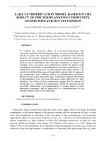
In [1-2], authors describer the Onering channel
models as the scatters are arranged around the mobile
station (MS), from which the scatters are assumed to
locate on a ring with the radius 𝑅𝑅 as in Fig.1.
BS
n
𝐵𝐵𝐵𝐵
𝑀𝑀𝑀𝑀
𝑓𝑓𝑛𝑛,𝑙𝑙 = 𝑓𝑓𝑚𝑚𝑚𝑚𝑚𝑚 cos�𝜙𝜙𝑛𝑛,𝑙𝑙
− 𝛼𝛼𝜈𝜈 �.
2.1. The Onering channel modelling approach
αBS
𝑛𝑛=1
𝑏𝑏𝑛𝑛,𝑢𝑢,𝑙𝑙 = 𝑒𝑒 𝑗𝑗𝑗𝑗(𝑼𝑼−2𝑢𝑢+1) 𝜆𝜆
Both of the channel models point out the closed
form expression the channel impulse responses which
depend on the same condition: the delay power
function, the number of transmit and receive antennas.
∆d s
� 𝑎𝑎𝑛𝑛,𝑠𝑠,𝑙𝑙 𝑏𝑏𝑛𝑛,𝑢𝑢,𝑙𝑙 𝑒𝑒 𝑗𝑗�2𝜋𝜋𝑓𝑓𝑛𝑛,𝑙𝑙𝑡𝑡+𝜃𝜃𝑛𝑛,𝑙𝑙� × 𝛿𝛿(𝜏𝜏 − 𝜏𝜏𝑙𝑙 ),
𝑑𝑑𝑠𝑠
2. The wideband and frequency selective Onering
and SCM channel modelling methods
𝜙𝜙𝑛𝑛𝑀𝑀𝑀𝑀 and 𝜙𝜙𝑛𝑛𝐵𝐵𝐵𝐵 are the arrival and departure angles of
the reflection path n, which come from the scatter
𝐵𝐵𝐵𝐵
is the maximal departure angle of the
Sn. 𝜙𝜙𝑚𝑚𝑚𝑚𝑚𝑚
transmitting signal. αv is the angle from the horizontal
of the velocity vector of MS.
2.2. The SCM channel modelling approach in NLOS
environment
v
𝜑𝜑ℒ−1
Sn
𝑁𝑁𝑙𝑙
𝑎𝑎𝑛𝑛,𝑠𝑠,𝑙𝑙 = 𝑒𝑒 𝑗𝑗𝑗𝑗(𝑺𝑺−2𝑠𝑠+1) 𝜆𝜆 �cos(𝛼𝛼𝐵𝐵𝐵𝐵)+𝜙𝜙𝑚𝑚𝑚𝑚𝑚𝑚 sin(𝛼𝛼𝐵𝐵𝐵𝐵
The structure of this paper is as follows: Section
2 studies the two channel modelling methods of the
Onering and SCM channel by the cross-correlation
functions. The interpolation techniques for 2×2
MIMO-OFDM system are introduced in section 3 and
4. Section 5 shows the simulation results and
discussions. Conclusions are given in Section 6.
𝑦𝑦
𝑐𝑐𝑙𝑙
α MS
αv
∆d u
𝐼𝐼ℒ−1
𝜑𝜑ℒ
−𝜑𝜑ℒ
𝐼𝐼ℒ
x
𝐼𝐼ℒ
−𝜑𝜑ℒ−1 𝐼𝐼
ℒ−1
R
Fig. 1. The scatering Onering model [4]
In the MIMO system with 𝑆𝑆 (𝑠𝑠 = 1,2, … 𝑆𝑆)
transmit antennas and 𝑈𝑈 (𝑢𝑢 = 1,2, … 𝑈𝑈) receive
antennas, 𝑑𝑑𝑠𝑠 and 𝑑𝑑𝑢𝑢 are the distance of base station
(BS) and MS antenna element𝑠𝑠, respectively, the
channel impulse response (CIR) in time domain
𝑂𝑂𝑂𝑂
(𝜏𝜏, 𝑡𝑡) is
modelled by the Onering channel method ℎ𝑢𝑢,𝑠𝑠
given as [1] with the angles αBS, αMS are the angles of
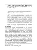
Fig. 2. SCM with one cluster of scatters [3]
The SCM is depicted in Fig.2, there are 𝑆𝑆 element
linear BS array and 𝑈𝑈 element linear MS array, the
channel impulse respond function is given for the
wideband frequency channel as, where τ is the time
delay of the channel:
32
Journal of Science & Technology 139 (2019) 031-036
�𝐺𝐺𝐵𝐵𝐵𝐵 (𝜃𝜃𝑛𝑛,𝑚𝑚,𝐴𝐴𝐴𝐴𝐴𝐴 ) 𝑒𝑒𝑒𝑒𝑒𝑒�𝑗𝑗�𝑘𝑘𝑑𝑑𝑠𝑠 𝑠𝑠𝑠𝑠𝑠𝑠�𝜃𝜃𝑛𝑛,𝑚𝑚,𝐴𝐴𝐴𝐴𝐴𝐴 � + 𝛷𝛷𝑛𝑛,𝑚𝑚 ��⎫
𝑀𝑀 ⎧
⎪
⎪
𝑃𝑃
𝜎𝜎
𝑛𝑛
𝑆𝑆𝑆𝑆
𝑆𝑆𝑆𝑆𝑆𝑆 (𝑡𝑡)
=�
ℎ𝑢𝑢,𝑠𝑠,𝑛𝑛
�
.
× �𝐺𝐺𝑀𝑀𝑀𝑀 �𝜃𝜃𝑛𝑛,𝑚𝑚,𝐴𝐴𝐴𝐴𝐴𝐴 � 𝑒𝑒𝑒𝑒𝑒𝑒�𝑗𝑗𝑗𝑗𝑑𝑑𝑢𝑢 𝑠𝑠𝑠𝑠𝑠𝑠�𝜃𝜃𝑛𝑛,𝑚𝑚,𝐴𝐴𝐴𝐴𝐴𝐴 ��
𝑀𝑀
⎨
⎬
𝑚𝑚=1 ⎪
⎪
× 𝑒𝑒𝑒𝑒𝑒𝑒�𝑗𝑗𝑗𝑗‖𝑣𝑣‖ 𝑐𝑐𝑐𝑐𝑐𝑐�𝜃𝜃𝑛𝑛,𝑚𝑚,𝐴𝐴𝐴𝐴𝐴𝐴 − 𝜃𝜃𝑣𝑣 � 𝑡𝑡�
⎩
⎭
(3)
𝑆𝑆𝑆𝑆𝑆𝑆
𝑆𝑆𝑆𝑆𝑆𝑆
ℎ𝑢𝑢,𝑠𝑠,𝑛𝑛
(𝜏𝜏, 𝑡𝑡) = ℎ𝑢𝑢,𝑠𝑠,𝑛𝑛
(𝑡𝑡)𝛿𝛿(𝜏𝜏 − 𝜏𝜏𝑛𝑛 )
We assumed the lognormal shadow fading and
antenna gain of both BS and MS are equal to one. The
𝑁𝑁𝑁𝑁𝑁𝑁𝑁𝑁
is given as [4]:
transfer function 𝐻𝐻𝑢𝑢𝑢𝑢𝑢𝑢
𝑁𝑁𝑁𝑁𝑁𝑁𝑁𝑁 (𝑓𝑓,
𝐻𝐻𝑢𝑢𝑢𝑢𝑢𝑢
𝑡𝑡)
𝑁𝑁
= � ℎ𝑢𝑢,𝑠𝑠,𝑛𝑛 (𝑡𝑡) × exp(−j2𝜋𝜋𝜏𝜏𝑛𝑛 𝑓𝑓),
𝑛𝑛=1
channel coefficient in the all of OFDM symbols and
ℎ(𝑘𝑘); 𝑘𝑘 = 1, 2 … 𝑁𝑁𝑝𝑝𝑝𝑝𝑝𝑝𝑝𝑝𝑝𝑝 is the channel coefficient in the
pilot symbols in the time domain, the closed form
expression data symbols bases on pilot positions is as
following as in equation (7). The effectiveness of the
channel estimation in interpolation methods depends
on the 𝐿𝐿 step value as the same as the LI.
(4)
Therefore, we have:
𝑁𝑁𝑁𝑁𝑁𝑁𝑁𝑁 (𝑓𝑓,
𝑡𝑡) =
𝐻𝐻𝑢𝑢𝑢𝑢𝑢𝑢
𝑃𝑃
𝑛𝑛 𝑀𝑀
∑𝑁𝑁
𝑛𝑛=1 � ∑𝑚𝑚=1 �
𝑀𝑀
exp(−j2𝜋𝜋𝜏𝜏𝑛𝑛 𝑓𝑓).
𝑒𝑒𝑒𝑒𝑒𝑒�𝑗𝑗[𝑘𝑘𝑑𝑑𝑠𝑠 𝑠𝑠𝑠𝑠𝑠𝑠�𝜃𝜃𝑛𝑛,𝑚𝑚,𝐴𝐴𝐴𝐴𝐴𝐴 � + 𝛷𝛷𝑛𝑛,𝑚𝑚 ]� ×
exp�𝑗𝑗𝑗𝑗𝑑𝑑𝑢𝑢 sin�𝜃𝜃𝑛𝑛,𝑚𝑚,𝐴𝐴𝐴𝐴𝐴𝐴 �� ×
exp�𝑗𝑗𝑗𝑗‖𝑣𝑣‖ cos�𝜃𝜃𝑛𝑛,𝑚𝑚,𝐴𝐴𝐴𝐴𝐴𝐴 − 𝜃𝜃𝑣𝑣 �𝜏𝜏�
(5)
𝑁𝑁
ℎ(𝑛𝑛) = �
𝑛𝑛=1
(7)
This method has been introduced in [12]. With
�𝑖𝑖,𝑙𝑙 is the channel coefficient at
the assumption that 𝐻𝐻
𝑡𝑡ℎ
�𝑖𝑖′,𝑝𝑝 is the
𝑖𝑖 OFDM symbol and the 𝑙𝑙 𝑡𝑡ℎ sub-carrier, 𝐻𝐻
channel coefficient at the 𝑝𝑝𝑡𝑡ℎ sub-carrier and the 𝑖𝑖 ′𝑡𝑡ℎ
OFDM symbol that contains the pilot data, the input of
Wiener filter is described as:
3. Cancellation methods for 2×2 MIMO-OFDM
system
�𝑖𝑖,𝑙𝑙 = ∑𝑖𝑖 ′ ,𝑝𝑝 𝑤𝑤𝑖𝑖 ′ ,𝑝𝑝,𝑖𝑖,𝑙𝑙 𝐻𝐻
�𝑖𝑖 ′ ,𝑝𝑝 ,
𝐻𝐻
In this section, the three popular interpolation
methods: Linear, Sinc and Wiener interpolation are
applied to study the performance of MIMO-OFDM
system.
(8)
Set the matrix coefficient of the filter as:
(9)
𝑊𝑊𝑖𝑖,𝑙𝑙𝑇𝑇
= (𝑤𝑤1,1,𝑖𝑖,𝑙𝑙 , … , 𝑤𝑤𝑖𝑖 ′ ,𝑝𝑝,𝑖𝑖,𝑙𝑙 , … , 𝑤𝑤(ℓ𝑡𝑡 −1)𝐷𝐷𝑡𝑡+1,�ℓ𝑓𝑓−1�𝐷𝐷𝑓𝑓+1,𝑖𝑖,𝑙𝑙 ),
3.1. The Linear Interpolation (LI)
Therefore, we have :
With the assumption of that the interpolation
approach is in shift invariant, LI [6]-[9] relies on two
consecutive pilot positions in both time and frequency
domains.
�𝑖𝑖,𝑙𝑙 = 𝑊𝑊𝑖𝑖,𝑙𝑙𝑇𝑇 𝐻𝐻
�𝑖𝑖′,𝑝𝑝 .
𝐻𝐻
(10)
where ℓ𝑡𝑡 , ℓ𝑓𝑓 are the number of OFDM symbols that
contain pilots in the time and frequency axis,
respectively, 𝑤𝑤𝑖𝑖 ′ ,𝑝𝑝,𝑖𝑖,𝑙𝑙 is the filter coefficients. 𝐷𝐷𝑓𝑓 and 𝐷𝐷𝑡𝑡
are distance of pilots in frequency and time domain,
respectively.
If the frequency interval of the neighboring pilot
subcarrier is 𝐿𝐿 , the index of the non-pilot subcarrier
between two adjacent pilots is 𝑙𝑙, the index of pilot
subcarriers is 𝑝𝑝. The transfer function for non-pilot
subcarriers between 𝑘𝑘 𝑡𝑡ℎ and (𝑘𝑘 + 1)𝑡𝑡ℎ pilots is
described as:
4. Description the 𝟐𝟐 × 𝟐𝟐 MIMO-OFDM system
We consider a 2×2 MIMO system as in Fig.3 with
the transmitter and receiver. In the transmitter, signal
is modulated by QAM-64, then using SFBC to
advantage diversity in space and frequency domain.
(6)
where 𝐻𝐻𝑝𝑝 (𝑘𝑘) is the transfer function of the pilot.
3.2. The Sinc Interpolation (SI)
This method has been introduced in [10]-[11].
With the assumption that ℎ(𝑛𝑛); 𝑛𝑛 = 1, 2 … 𝑁𝑁 is the
� ℎ(𝑘𝑘) ×
𝑘𝑘=1
𝜋𝜋(𝑛𝑛 − 𝑘𝑘𝑘𝑘)
)
𝐿𝐿
.
𝜋𝜋(𝑛𝑛 − 𝑘𝑘𝑘𝑘)
𝐿𝐿
sin (
�×
3.3. The Wiener Interpolation (WI)
whereby, θn,m,AoD and θn,m,AoA are the AoD and the AoA
for the mth sub‐path of the nth path; Φn,m is the phase of
the mth sub‐path of the nth path. The SCM method has
N paths (N = 6), each path has M sub‐path (M = 20).
𝑙𝑙
𝑙𝑙
� (𝑘𝑘𝑘𝑘 + 𝑙𝑙) = �1 − � 𝐻𝐻
� (𝑘𝑘) + � � 𝐻𝐻
� (𝑘𝑘 + 1).
𝐻𝐻
𝐿𝐿 𝑝𝑝
𝐿𝐿 𝑝𝑝
𝑁𝑁𝑝𝑝𝑝𝑝𝑝𝑝𝑝𝑝𝑝𝑝
33
Journal of Science & Technology 139 (2019) 031-036
5. Simulation results and discussions
Mapper
QAM
SFBC
Encoder
Demapper
QAM
SFBC
Decoder
OFDM
Modulator
Under the simulated condition of the Vehicle A
model C with the speed of 30𝑘𝑘𝑘𝑘/ℎ at 2𝐺𝐺𝐺𝐺𝐺𝐺, the
channel is independent in time domain and the channel
profile delay is described by LTE-A. The parameters
for simulation for channel modelling and the MIMOOFMD system can be given as in Table 1 with number
IFFT is number of symbol inverse fast Fourier transfer.
Fig.4 - Fig.9 are the results of the comparing the two
channel modelling methods when using Linear, SI and
Wiener interpolations, respectively in time domain
with the window step 𝐿𝐿 from 2 to 4.
Antenna
Mapping
OFDM
Demodulator
Antenna
Demapping
Channel
Estimation
Fig. 3. The 2 × 2 MIMO-OFDM system
In Fig.4 and Fig.5 the effectiveness of the Linear
cancelation methods of the MIMO 2x2 is compared in
the Onering and the SCM. The Onering has the SERs
higher than the SCM with the same window step of LI
are from 𝐿𝐿 = 2 to 𝐿𝐿 = 4, respectively. With the
increasing of step window L, the higher of the SERs,
because of the more decrease of the exactitude results.
The receiver basically do the visa versa of the
transmitter but channel estimator is added to increase
the system performance by using different
interpolation methods. The arrangement of user data,
reference signal and zero data in frequency domain
obey the rules that on the same 𝑖𝑖 𝑡𝑡ℎ symbol and the
same the 𝑘𝑘 𝑡𝑡ℎ sub-carrier, the existing reference signal
(pilot) in this antenna can be gotten by setting the other
to zero and vice versa.
Fig.6 and Fig.7 are the SERs comparison of SI in
two channel modellings. As one can see the SERs of
SCM is lower than of the Onering. One can see the
smaller of L, the better of the performance’s system.
We denote the square matrix 𝐹𝐹𝐿𝐿 with 𝑁𝑁𝐹𝐹𝐹𝐹𝐹𝐹 ×
𝑁𝑁𝐹𝐹𝐹𝐹𝐹𝐹 matrix and the RS can be generated in antenna 1
and 2, respectively as below with 𝑁𝑁𝐹𝐹𝐹𝐹𝐹𝐹 is number of
symbol fast fourier transfer:
𝑋𝑋𝑝𝑝,1 (𝑘𝑘) = 𝑒𝑒 −𝑗𝑗𝐷𝐷𝑓𝑓𝜋𝜋𝑘𝑘
2 /𝑁𝑁
2 /𝑁𝑁
𝑋𝑋𝑝𝑝,2 (𝑘𝑘) = 𝑒𝑒 −𝑗𝑗𝐷𝐷𝑓𝑓𝜋𝜋(𝑘𝑘+𝑀𝑀)
𝑀𝑀 = 𝑁𝑁𝐹𝐹𝐹𝐹𝐹𝐹 /𝐷𝐷𝑓𝑓
𝐹𝐹𝐹𝐹𝐹𝐹
𝐹𝐹𝐹𝐹𝐹𝐹
Fig.8 and Fig.9 are the SERs comparison of
Wiener interpolation which have the same conclusions
as the LI and SI. The SCM has better performance than
the Onering with each L and the SERs are lower at the
L=2.
(11)
Also,we can get the results of each window step
𝐿𝐿, the SERs of the LI are higher than the SI, the SERs
of the WI are lowest of the three interpolation methods.
We can see that if the step 𝐿𝐿 is increased the system
performance is decreased. In Onering channel model,
the SER results are higher than those obtained in the
SCM as can be seen in Table 2 in the case of 𝑆𝑆𝑆𝑆𝑆𝑆 =
14 𝑑𝑑𝑑𝑑.
The channel coefficients at the pilot possitions is as:
𝐻𝐻𝑝𝑝 (𝑘𝑘) = (𝑄𝑄𝐻𝐻 𝑄𝑄)−1 𝑄𝑄𝐻𝐻 𝑌𝑌𝑟𝑟
(12)
𝑄𝑄 = �𝑑𝑑𝑑𝑑𝑑𝑑𝑑𝑑 �𝑋𝑋𝑝𝑝,1 (𝑘𝑘)� × 𝐹𝐹𝐿𝐿 , 𝑑𝑑𝑑𝑑𝑑𝑑𝑑𝑑 �𝑋𝑋𝑝𝑝,2 (𝑘𝑘)� × 𝐹𝐹𝐿𝐿 �
Table 1. Simualtion parameters for channel modelling
methods
0.9
Value
5 MHz
𝜏𝜏max = 2473.96 ns
𝛥𝛥𝛥𝛥𝑠𝑠 = 10λ
𝛥𝛥𝛥𝛥𝑢𝑢 = 0.5λ
11
300
128
512
𝑇𝑇𝑠𝑠 = 130.21 𝑛𝑛𝑛𝑛
0.8
0.7
0.6
SER
Parameters
Bandwidth
Maximum access delay
Antenna array distance BS
Antenna array distance MS
No of OFDM symbols
Number of sub-carrier
Length of guard interval (GI)
Number of IFFT
Frequency sampling
Linear Interpolation Onering channel model LTE-A
1
0.5
0.4
0.3
0.2
Linear Interpolation L = 2
0.1
Linear Interpolation L = 3
Linear Interpolation L = 4
0
2
4
6
8
10
SNR in dB
Fig. 4. SER of LI of ORM
34
12
14
Journal of Science & Technology 139 (2019) 031-036
Linear Interpolation SCM channel model LTE-A
1
Wiener Interpolation in Onering LTE-A
0.9
0.9
0.8
0.8
0.7
0.7
0.6
0.6
SER
SER
0.5
0.4
0.5
0.4
0.3
0.3
0.2
Channel coefficient L = 2
0.2
Linear Interpolation L = 2
0.1
Channel coefficient L = 3
Linear Interpolation L = 3
Linear Interpolation L = 4
0
2
4
6
8
10
12
Channel coefficient L = 4
0.1
14
0
2
4
SNR in dB
6
8
10
12
14
SNR in dB
Fig. 5. SER of LI of SCM
Fig. 8. SER of WI of ORM
Sinc Interpolation Onering channel model LTE-A
1
Sinc Interpolation L = 2
0.9
SInc Interpolation L = 3
Wiener Interpolation SCM channel model LTE-A
1
Sinc Interpolation L = 4
0.8
Wiener Interpolation L = 2
0.9
Wiener Interpolation L = 3
0.7
Wiener Interpolation L = 4
0.8
0.6
0.7
SER
0.5
0.6
SER
0.4
0.3
0.5
0.4
0.2
0.3
0.1
0.2
0
2
4
6
8
10
12
14
0.1
SNR in dB
Fig. 6. SER of SI of ORM
0
LI
SI
L
2
3
4
2
3
4
2
3
4
ORM
.28
.7
.89
.24
.41
.69
.18
.19
.22
SCM
.22
.3
.56
.17
.19
.25
.17
.18
.21
WI
0.7
SER
0.6
0.5
0.4
0.3
0.2
Sinc Interpolation L = 2
Sinc Interpolation L = 4
4
12
14
References
Sinc Interpolation L = 3
2
10
Our paper studies interpolation methods applied
to estimate the channel coefficients of MIMO 2x2
systems in both channel modelling methods: the SCM
and the Onering channel model in the suburban macrocell. From the SER results, of the three interpolation
methods, the WI has the best result, the following is
the SI in the same above characteristic of the channel.
The SER results depend on the pilot positions by the
step 𝐿𝐿 in the rule of the higher of the 𝐿𝐿 step, the worse
of the performance system can get. As mention above,
in the case of NLOS, the system performance of
MIMO channel is researched in two channel
modelling, the effectiveness of the cancellation
methods in the SCM is better than in the Onering
channel model.
0.8
0
8
6. Conclusions
0.9
0.1
6
Fig. 9. SER of WI of SCM
Sinc Interpolation SCM channel model LTE-A
1
4
SNR in dB
Table 2. SERs of interpolation methods, 𝑆𝑆𝑆𝑆𝑆𝑆 = 14 dB
when window step 𝐿𝐿 = 2 to 𝐿𝐿 = 4
SERs
2
6
8
10
12
[1]
14
SNR in dB
2012.
Fig. 7. SER of SI of SCM
35
Pätzold M, Mobile Radio Channels, 2nd edn, Wiley,
Journal of Science & Technology 139 (2019) 031-036
[2]
Thuong N., Van Duc N., Phuong Dang, Luong
PhamVan, Thu Nga N., & Patzold, M. (2012), A
performance study of LTE MIMO-OFDM systems
using the extended one-ring MIMO channel model. In
The 2012 International Conference on Advanced
Technologies for Communications (ATC 012) (pp.
263–268).
[3]
3GPP, Technical Specification Group Radio Access
Network Spatial channel model for Multiple Input
Multiple Output (MIMO) simulation, pp. 25-996,
Release 10, Mar. 2011.
[4]
Nguyen, T. Nga., & Nguyen, V. D. (2016), Research
article, A performance comparison of the SCM and the
Onering channel modeling method for MIMOOFDMA systems, (October), 3123–3138.
[5]
Jiang Y, Varanasi MK, Li J, Performance Analysis of
ZF and MMSE Equalizers for MIMO System: An InDepth Study of the High SNR Regime, IEEE
Transactions on Information Theory 2011, 2008–2026.
[6]
[7]
S. Hayking, Adaptive Filter Theory, Prentice Hall,
1986, USA.
[8]
Hajizadeh, F. R., Mohamedpor, S. K., & Tarihi, T. M.
R. (2010), Channel Estimation in OFDM System
Based on the Linear Interpolation, FFT and Decision
Feedback, 484–488, 18th Telecommunications forum
TELFOR 2010.
[9]
Zhang, X., & Yuan, Z. (n.d.), The Application of
Interpolation Algorithms in OFDM Channel
Estimation, ijssst, Vol-17, No-38, paper11, pp. 1–5.
[10] Nasreddine, M., Bechir, N., Hakimiand, W., &
Ammar, M. (2014), Channel Estimation for Downlink
LTE System Based on LAGRANGE Polynomial
Interpolation, ICWMC 2014: The Tenth International
Conference on Wireless and Mobile Communications,
65–69.
[11] Schanze, T. (1995), Sinc interpolation of discrete
periodic signals, IEEE Transactions on Signal
Processing, 43(6), 1502–1503.
Alan V. Oppenheim and Ronald W. Schafer, Discreate
Time signal processing, chapter 7, pp. 473-475,
Prentice Hall, 1999.
[12] Li du and Louis Scharf, (1990), Wiener Filters for
Interpolation and Extrapolation, Conference Record
Twenty-Fourth Asilomar Conference on Signals,
Systems and Computers.
36