Optimization of steel moment frames with panel-zone design using an adaptive differential evolution
Bạn đang xem bản rút gọn của tài liệu. Xem và tải ngay bản đầy đủ của tài liệu tại đây (1.05 MB, 11 trang )
Journal of Science and Technology in Civil Engineering NUCE 2020. 14 (2): 65–75
OPTIMIZATION OF STEEL MOMENT FRAMES WITH
PANEL-ZONE DESIGN USING AN ADAPTIVE
DIFFERENTIAL EVOLUTION
Viet-Hung Truonga , Ha Manh Hungb,∗, Pham Hoang Anhb , Tran Duc Hocc
a
Faculty of Civil Engineering, Thuyloi University, 175 Tay Son street, Dong Da district, Hanoi, Vietnam
b
Faculty of Building and Industrial Construction, National University of Civil Engineering,
55 Giai Phong road, Hai Ba Trung district, Hanoi, Vietnam
c
Department of Construction Engineering and Management, Ho Chi Minh City University of Technology,
Vietnam National University - HCMC, 268 Ly Thuong Kiet Street, District 10, Ho Chi Minh City, Vietnam
Article history:
Received 12/02/2020, Revised 16/03/2020, Accepted 18/03/2020
Abstract
Optimization of steel moment frames has been widely studied in the literature without considering shear deformation of panel-zones which is well-known to decrease the load-carrying capacity and increase the drift of
structures. In this paper, a robust method for optimizing steel moment frames is developed in which the panelzone design is considered by using doubler plates. The objective function is the total cost of beams, columns,
and panel-zone reinforcement. The strength and serviceability constraints are evaluated by using a direct design
method to capture the nonlinear inelastic behaviors of the structure. An adaptive differential evolution algorithm
is developed for this optimization problem. The new algorithm is featured by a self-adaptive mutation strategy
based on the p-best method to enhance the balance between global and local searches. A five-bay five-story
steel moment frame subjected to several load combinations is studied to demonstrate the efficiency of the proposed method. The numerical results also show that panel-zone design should be included in the optimization
process to yield more reasonable optimum designs.
Keywords: direct design; differential evolution; optimization; panel-zone; steel frame.
/>
c 2020 National University of Civil Engineering
1. Introduction
Moment frame or moment-resisting frame is a frame with rigid beam-to-column connections.
This structure has been widely used for a long time since it is suitable for multi-story buildings and
superior earthquake resistance. Cost optimization of a moment frame is often to minimize the total
structural cost or weight by selecting the sections of beams and columns in a discrete pre-defined
list while all strength, serviceability and constructability constraints are guaranteed. This implies that
cost optimization of moment frames is highly nonlinear and finding optimal solutions is impossible
in almost case studies. Normally, meta-heuristic algorithms that can find sufficiently good but not
optimal solutions are employed. The efficiency of meta-heuristic algorithms for structural design has
been proved by the results of many studies in the literature, for example, Refs. [1–8]. Besides that,
lots of meta-heuristic algorithms have been proposed such as big bang–big crunch (BB–BC) [9],
∗
Corresponding author. E-mail address: (Hung, H. M.)
65
Truong, V.-H., et al. / Journal of Science and Technology in Civil Engineering
differential evolution (DE) [10], enhanced colliding bodies optimization (ECBO) [11], and harmony
search (HS) [12].
In the optimization process, strength and serviceability constraints are evaluated by using structural analyses that can be categorized into 2 groups such as linear and nonlinear analyses. Using nonlinear analyses not only captures the nonlinear inelastic behaviors of structures but also yields lighter
and more realistic optimum designs [13]. Among several methods for structural nonlinear analysis, the
direct design has been favored recently. In the direct design approach, the ultimate load-carrying capacity of the whole system and nonlinear relationship between structural responses and applied loading are captured instead of the individual member check in the member-based design method. Some
researches in the literature about direct design and using direct design for structural optimization are
Refs. [14–18], among others. However, structural analysis using direct design methods requires much
more time-computing compared to linear analysis methods, hence structural optimization using direct
design often has an excessive computational effort.
In this study, a robust method for optimization of steel moment frames using a direct design
method is introduced. A major advantage of the proposed method is that the time-computing is much
more reduced, so the optimization of nonlinear steel frames can be performed with a very large number of objective function
evaluations
in an acceptable
computational
time. function
To do this, a direct design
steel frames
can be performed
with a very large
number of objective
method using beam-column
elements
is
used
that
saves
significant
time-computing.
Furthermore, an
evaluations in an acceptable computational time. To do this, a direct design method
improved DE methodusing
is developed
using
a
self-adaptive
mutation
strategy
based
on
the
p-best method,
beam-column elements is used that saves significant time-computing.
named as EapDE, toFurthermore,
enhance anthe
balance
between
globalusing
andalocal
searches.
The panel-zone shear
improved
DE method
is developed
self-adaptive
mutation
deformation is prevented
reinforcement
of panel-zones
usingtodoubler
plates.
strategyby
based
on the p-best method,
named as EapDE,
enhance the
balanceA five-bay five-story
globalto
andseveral
local searches.
panel-zone shearisdeformation
is prevented
steel moment framebetween
subjected
load The
combinations
studied to
demonstrate the efficiency
by reinforcement of panel-zones using doubler plates. A five-bay five-story steel
of the proposed method.
moment frame subjected to several load combinations is studied to demonstrate
the efficiency of the proposed method.
2. Panel-zone reinforcement
method
2. Panel-zone reinforcement method
Fig 1. Typical panel-zone area [20]
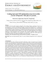
Figure 1. Typical panel-zone area [19]
Considering a typical panel-zone area as presented in Fig 1. The shear force
at the panel-zone is calculated as [19]:
Considering a typical panel-zone area as presented in Fig. 1. The shear force at the panel-zone is
M
M
calculated as [20]:
(1)
å Fu = 0.95ud1 + 0.95ud2 - Vu ,
Mu2
m1Mu1
m2
Fu =
+
− Vu
(1)
0.95dm1 moments
0.95d
where M u1 and M u2 are the factored
onm2the left and right beams,
where Mu1 and Mu2 are the factored moments on the left and right beams, respectively; Vu is the
factored
forceheights
on column;
and dand
the beams, respectively.
d m1 right
factored shear force respectively;
on column;Vu dism1theand
dm2 shear
are the
of the
left
m2 are
heights of the right and left beams, respectively.
The nominal strength at the panel66
Truong, V.-H., et al. / Journal of Science and Technology in Civil Engineering
The nominal strength at the panel-zone is calculated as [20]:
Vn = 0.60Fy dc tw
Vn = 0.60Fy dc tw 1.4 −
Pr
Py
if Pr ≤ 0.40Py
(2a)
if Pr > 0.40Py
(2b)
where Fy is the yield strength of steel for the column; dc and tw are the height and the thickness of
the column web, respectively; Pr and Py are the axial force and axial yield strength of the column,
respectively. Py is determined as: Py = Fy Ag where Ag is the cross-sectional area of the column. If
Fu is greater than φVn , the panel-zone area will be yielded and the reinforcement design of the
panel-zone area is necessary. φ is the resistance factor which is equal to 0.9 in this study.
Panel-zones can be designed by using [19]: (i) reinforcing the column web to guarantee the static
behaviors for the panel-zone area and so the panel-zone shear deformation is ignored; and, (ii) allowing panel-zone yielded and then the panel-zone shear deformation has to be considered in structural
design. In both approaches, the panel-zone reinforcement by using doubler plates or stiffeners requires. However, the first approach is simpler in the analysis but requires thicker doubler plates than
the second approach. In this paper, the design of panel-zones using the first approach is used. The
total thickness of the required doubler plate(s), t plate , is calculated as follows:
t plate =
Fu
φ0.60Fy dc − tw
t plate =
Fu
φ0.60Fy dc 1.4 −
Pr
Py
− tw
if Pr ≤ 0.40Py
(3a)
if Pr > 0.40Py
(3b)
3. Formulation of the optimization problem
3.1. Objective function
Cost optimization of steel moment frames is defined as the minimization of the total cost of the
structure including the cost of beams, columns, and panel-zone reinforcement. The cost of beams and
columns is easily predicted by using the unit price of steel and the total weight of these members.
However, the cost of panel-zone reinforcement including the material cost of doubler plates and welding cost is highly dependent on the labor cost that is based on the characteristics and location of each
structure. For simplicity, Ha et al. [17] proposed an equation to transfer the panel-zone reinforcement
cost to structural steel cost based on the current material and labor costs in the USA. The cost of a
panel-zone reinforcement can be estimated as [17]
T panel = c structuralsteel × 25000 × t plate × (h + b) + 7850 × t plate × h × b (kg)
(4)
where h and b are the height and width of the doubler plate(s) with their unit of meter, respectively;
c structuralsteel is the steel material price per weight. Assuming that the height of the doubler plate at
a panel-zone is equal to the greater value of the heights of the left and right beams. And, the width
of the doubler plated is equal to 95% the height of the column web. The cost objective function of
the structure is therefore simplified as the following weight function by neglecting the steel price per
67
Truong, V.-H., et al. / Journal of Science and Technology in Civil Engineering
weight (or assuming c structuralsteel = 1):
min T (X) = W (X) + W panel (X)
ni
nm
+
A (xi )
=ρ
L
q
i=1
q=1
X = (x1 , x2 , . . . , xnm ) ,
np
25000 × t plate, j × h j + b j + 7850 × t plate, j × h j × b j
(5)
j=1
xi ∈ [1, U Bi ]
where W (X) and W panel (X) are the total weight of the beams and columns and the reinforcement
cost of panel-zones, respectively; X is the vector of design variables which are the integer values
representing the sequence numbers of the cross-section types used for the beams and column in the
variable space; U Bi is the number of W-shaped sections available for the ith group of beams and
columns; ρ is the specific weight of steel; ni is the number of frame members in the ith group; A (xi )
is the cross-section of the ith design variable; and, Lq is the fabricated length of member q in the ith
group; np is the number of reinforced panel-zones. Note that, the length of a beam is the distance
between two column nodes but not include the column height.
3.2. Constraints
In this study, constructability constraints include the provisions at column-to-column connections
so that the height of the upper column segment must not be larger than the lower column segment.
Besides, at the beam-to-column connections, the width of the beam flanges should not be greater
than the width of the column flange. If the beam is connected to the column web, the width of the
beam flange should not be greater than the height of the column web. These conditions are formulated
as follows:
uppercolumn
D
con
Ci,1 (X) = clowercolumn − 1 ≤ 0, i = 1, . . . , nc−c
(6a)
Dc
i
bb f
con
(X) =
Ci,2
− 1 ≤ 0, i = 1, . . . , nb−c1
(6b)
bc f i
bb f 2
con
(X) =
Ci,3
− 1 ≤ 0, i = 1, . . . , nb−c2
(6c)
Tc i
in which nc−c , nb−c1 and nb−c2 are the connection numbers of column-to-column, beam-to-column
uppercolumn
flange, and beam-to-column web, respectively; Dc
and Dlowercolumn
are the upper- and lowerc
column segment depths at a column-to-column joint, respectively; bc f and bb f are the flange widths
of the column and beam at a beam-to-column flange joint, respectively; bb f 2 and T c are the beam
flange width column web height at a beam-to-column web joint.
In this paper, the strength constraint of the frame subjected to the jth strength load combination is
evaluated by using direct design as presented as follows:
C str
j (X) = 1 −
Rj
≤ 0,
Sj
j = 1, . . . , n str
(7)
where R j and S j are the structural load-carrying capacity and the factored loads. The ratio R j /S j is
called the structural ultimate load factor.
68
Truong, V.-H., et al. / Journal of Science and Technology in Civil Engineering
The serviceability constraints include the lateral drift for the top story sway and inter-story drifts
for each floor that are formulated as
dri f t
Ck
(X) =
Ckint,l (X)
=
Dk
− 1 ≤ 0,
Duk
dkl
dku,l
− 1 ≤ 0,
j = 1, . . . , n str ,
k = 1, . . . , n ser
l = 1, . . . , n story ,
k = 1, . . . , n ser
(8a)
(8b)
where Dk and Duk are the lateral drift of the top story and its allowable value, respectively; dkl and
dku,l are the inter-story drift of the lth story and its allowable value, respectively; n story is the number of
structural stories; and, n ser is the number of the considered serviceability load combinations.
3.3. Constraint handling using the penalty function method
The above-constrained optimization problem can be transformed into an unconstrained optimization problem by using the penalty function method as follows:
T uncons (X) = W (X) × (1 + αcon β1 + α str β2 + αins β3 ) + W panel (X)
where
(9a)
ncon
β1 =
con
con
con
max Ci,1
, 0 + max Ci,2
, 0 + max Ci,3
,0
j=1
n str
β2 =
max C str
j ,0
(9b)
j=1
n ser
β3 =
k=1
n story
max C dri f t , 0 +
max Ckint,l , 0
k
l=1
in which αcon , α str , and αins are the penalty parameters of the geometric constructability, strength, and
inter-story drift constraints, respectively.
4. Improved DE algorithm
The DE, a population-based metaheuristics algorithm, was proposed by Storn and Price [10] in
1997. Up to now, many modified versions of DE have been developed in the literature and prove
this algorithm as one of the most efficient methods and is suitable for solving various optimization
problems. Regarding the optimization of steel frames, the authors and the colleague introduced a new
and efficient DE-based method in 2020, named as mEpDE [17]. Compared to the conventional DE
method, mEpDE has several improvements such as (i) using a new mutation strategy based on the pbest method to balance the local and global searches; (ii) Developing the multi-comparison technique
(MCT) to efficiently reduce the number of structural analysis calls for evaluating the strength and
serviceability constraints; (ii) Developing the Promising Individual Method (PIM) that effectively
chooses trial individuals; (iv) Avoiding repetitive same individual evaluations by using a matrix to
contain all evaluated individuals. Numerical results provided in Ref. [17] showed the robustness of
mEpDE compared to several new and efficient metaheuristic algorithms for steel frame optimization.
However, in this study, we will use a self-adaptive mutation strategy based on the p-best method that
69
Truong, V.-H., et al. / Journal of Science and Technology in Civil Engineering
can improve the performance of mEpDE for optimization of steel moment frames. Other techniques
remain the same as implemented in mEpDE. The new optimization method is named as EapDE.
In the conventional DE method, ‘DE/rand/1’ and ‘DE/best/1’ are two common mutation strategies
that have opposite effects in the balance of global and local searches of the optimization. Specifically,
the trial individual is generated based on a random individual and the best individual corresponding
to using ‘DE/rand/1’ and ‘DE/best/1’. Therefore, ‘DE/rand/1’ is better at global exploration but converges more slowly compared to ‘DE/best/1’. To take advantage of these methods, the ‘DE/pbest/1’
strategy is used in the mEpDE method where p for the kth iteration of the optimization process is
calculated as
k−1
p (k) = A × nm −B× total_iteration−1
(10)
where A and B are predefined parameters; total_iteration is the predefined value for the maximum
number of iterations. In the ‘DE/pbest/1’ strategy, the trial individual is generated based on a random
individual in the top 100p% (p ∈ (0, 1]) of the current population. Furthermore, from Eq. (10) we
have p (1) = A so A is the parameter to control the number of the best individuals used at the beginning of the optimization process. And, if B increases the decline of p increases. Hence, B is used
to control the decline speed of the number of the best individuals used. Besides that, if A and B are
equal to 1.0, ‘DE/rand/1’ and ‘DE/best/1’ are used at the beginning and the end of the optimization,
respectively. Eq. (10) is an approach where the value p is predefined without considering the population characteristics and their changes in the optimization process. It should be noted that the diversity
and convergence of the population can be predicted based on the change values of the individuals
in the population. Many indicators representing the diversity of the population are developed in the
literature, for example [21]:
DI(t)
1
=
NP
NP
D
k=1
i=1
xk,i − xC,i 2
,
U B
xi − xiLB
xC,i
1
=
NP
NP
xk,i
(11)
k=1
where NP is the number of individuals in the population; D is the number of design variables; xk,i
is the value of the design variable ith of the individual kth ; xiU B and xiLB are the upper- and lowerbounds of the design variable ith ; and, DI(t) is defined as the diversity index of the population at the
kth iteration. DIt represents the individual distribution around the center of the current population.
If DI(t) is great, we can guess that the individuals are still highly dispersed, so maintenance of the
diversity of individuals is preferred or large p value should be used and vice versa. In light of this, the
following equation is used to calculate p [21]:
p=
DI(t)
1
1
+ 1−
×
NP
NP
DI(0)
(12)
5. Case study
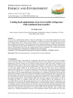
In this section, a five-bay five-story steel moment frame with the geometry presented in Fig. 2
is studied to demonstrate the efficiency of the proposed method. The initial story out-of-plumbness
is 1/500 . The initial imperfection of beams is not considered. The steel material used for the whole
structure is ASTM A992 with the elastic modulus of E = 200 GPa, the yield stress of Fy = 344.7 MPa
and the weight per unit volume of 7,850 kg/m3 . Doubler plates are reinforced using 4 thicknesses such
as 3/16 inches (4.7625 mm), 3/8 inches (9.525 mm), 5/8 inches (15.875 mm), and 1 inches (25.4 mm).
70
p=
W
Truong, V.-H., et al. / Journal of Science and Technology in Civil Engineering
DL, LL
DL, LL
12
3
W
5
LL = 25 kN/m
W = 28 kN
8
2
W
5
DL, LL
1
W
4
DL, LL
1
1/500
6.0 m
4
1/500
6.0 m
5
7
13
7
1/500
2
DL, LL
10
4
DL, LL
10
7
1/500
11.0 m
11
10
DL, LL
10
2
DL, LL
DL, LL
13
7
10
5
8
DL, LL
11
11
DL, LL
10
DL, LL
DL, LL
14
8
3
11
8
DL, LL
10
DL, LL
DL, LL
11
12
6
14
DL, LL
11
DL = 35 kN/m
DL, LL
11
DL, LL
12
9
DL, LL
DL, LL
DL, LL
15
9
11
2
DL, LL
12
6
DL, LL
W
(12)
6.0 m
5 x 3.6 m = 18.0 m
5. Case study
1 æ
1 ö DI(t )
.
+ ç1 ÷´
NP è NP ø DI ( 0)
1
DL, LL
10
4
1/500
1
1/500
6.0 m
2. Five
bay-fivestory
story steel
[17][17]
Fig.Figure
2 Five
bay-five
steelframe
frame
The dead load (DL), live load (LL) and wind load (W) as presented in Fig. 2 are equal to 35 kN/m, 25
kN/m and 28 kN, respectively.
The columns and beams are grouped into 15 cross-sections where 267 sections from W10–W44
of AISC-LRFD are used for the beam members and 158 sections from W12, W14, W18, W21, W24,
and W27 are used for the column members. Two strength load combinations: (1.2DL + 1.6LL) and
(1.2DL + 1.6W + 0.5LL) and one serviceability load combination (1.0DL + 0.7W + 0.5LL) are considered. The allowable inter-story drift is h/400, where h is the frame story height. There are a total
of 21 constraints considered including 18 constructability constraints, 2 strength constraints, and 1
serviceability constraint.
To demonstrate the efficiency of the proposed method, only the mEpDE method is employed for
comparison since mEpDE is much better than several new and efficient optimization methods for the
optimization of steel frames as provided in Ref. [17]. The parameters used for the proposed method
and mEpDE are: NP = 25, max_iteration = 4000; A = 1.0; B = 1.0; scale factor F = 0.7; crossover
rate CR is randomly generated in the range (0,1). The termination of the optimization process is
defined as the best objective function is not improved in 1,000 consecutive iterations or the number
of iteration reaches max_iteration. The strength and serviceability constraints are evaluated by using
the PAAP program, a robust direct design program for steel structures [22].
Table 1 presents the best optimum designs obtained by using the proposed method (EapDE) and
mEpDE, where 20 optimization runs are performed for each case. As can be seen in this table, the
EapDE yields the best optimum design with a total weight of the frame of 18,566 kg, which is smaller
than one of mEpDE with 18,687 kg. The worst weight of the optimum design of 19,073 kg by using
EapDE is also smaller than 19,149 kg of mEpDE. This means that EapDE can find a better optimum
design of the frame than mEpDE. The required structural analyses of EapDE are only 22,733 that is
smaller than 20,462 of mEpDE. The reason is that, in the EapDE method, the p value is changed ac71
Truong, V.-H., et al. / Journal of Science and Technology in Civil Engineering
Table 1. Optimization results of five bay-five story steel frame
Element group of best design
1
2
3
4
5
6
7
8
9
10
11
12
13
14
15
Best weight (kg)
Beams weight (kg)
Columns weight (kg)
Panel cost of the best design (kg)
Normalized constraint evaluation of (1.2DL + 1.6LL)
Normalized constraint evaluation of (1.2DL + 1.6W + 0.5LL)
Normalized constraint evaluation of (1.0DL + 0.7W + 0.5LL)
Worst weight (kg)
Avg. weight (kg)
Avg. number of structural analysis
Avg. computational time (hour)
EapDE
mEpDE
W18 × 40
W18 × 40
W12 × 26
W24 × 62
W24 × 55
W24 × 55
W27 × 114
W24 × 62
W24 × 55
W12 × 22
W14 × 22
W16 × 26
W21 × 44
W24 × 55
W21 × 57
18,566
7,656
9,491
1,419
1.0058
1.3909
0.6354
19,073
18,707
22,733
6.2
W18 × 35
W14 × 30
W12 × 26
W24 × 68
W24 × 55
W24 × 55
W27 × 102
W24 × 62
W24 × 62
W14 × 22
W16 × 26
W16 × 26
W18 × 46
W24 × 55
W24 × 55
18,730
7,961
9,115
1,654
1.0042
1.4314
0.6238
19,149
18,872
20,462
6.2
Fig. 3 Convergence histories of best optimum designs
Figure 3. Convergence histories of best optimum designs
72
Truong, V.-H., et al. / Journal of Science and Technology in Civil Engineering
cording to the convergence speed of the population. Therefore, the diversity of the population remains
better than ones of mEpDE where the p value is predefined as discussed in Section 4. It is also should
be noted that with three load combinations considered, the total number of structural analyses for
this optimization problem is 300,000. Therefore, the time-computing of both methods is only about
6.2 hours although the total objective function evaluations of 300,000 are very great. This means that
both EapDE and mEpDE efficiently reduce the number of required structural analyses. Furthermore,
Fig. 3 presents the convergence histories of the best optimum designs of EapDE and mEpDE. As can
be seen in this figure, the convergence speeds of the two methods are almost the same. Besides that,
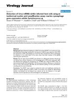
Fig. 4 shows the panel-zone reinforcement of the best optimum design of two methods.
6.0 m
m
6.0
W12x22
W12x22
1/500
1/500
11.0 m
m
11.0
W12x22
W12x22
1/500
1/500
6.0 m
m
6.0
6.0 m
m
6.0
W16x26
W16x26
W16x26
W16x26
W12x26
W12x26
55xx3.6
3.6mm==18.0
18.0mm
W18x40
W18x40
W18x40
W18x40
W12x22
W12x22
W18x40
W18x40
W24x55
W24x55
W24x55
W24x55
W12x22
W12x22
W24x55
W24x55
W24x55
W24x55
W14x22
W14x22
W18x40
W18x40
1/500
1/500
W14x22
W14x22
W24x62
W24x62
W21x44
W21x44
W14x22
W14x22
W24x62
W24x62
W24x55
W24x55
W21x44
W21x44
W14x22
W14x22
1/500
1/500
W18x35
W18x35 W18x35
W18x35 W14x30
W14x30 W14x30
W14x30 W12x26
W12x26
1/500
1/500
W24x55
W24x55
W16x26
W16x26
W24x62
W24x62
W12x22
W12x22
W24x62
W24x62
W24x55
W24x55
W24x55
W24x55
W24x55
W24x55
6.0 m
m
6.0
W12x22
W12x22
W24x55
W24x55
W16x26
W16x26
W27x114
W27x114 W27x114
W27x114 W24x62
W24x62
1/500
1/500
W14x22
W14x22
W21x57
W21x57
W27x114
W27x114 W27x114
W27x114 W24x62
W24x62
W12x22
W12x22
W14x22
W14x22
W24x62
W24x62
W18x40
W18x40
W18x40
W18x40
W12x22
W12x22
W16x26
W16x26
W24x62
W24x62
W12x26
W12x26
W14x22
W14x22
W18x40
W18x40
W14x22
W14x22
W18x40
W18x40
W16x26
W16x26
1/500
1/500
Design doubler
doubler plate(s)
plate(s) 1x3/16
1x3/16 (in)
(in)
Design
Design
doubler
plate(s)
1x3/8
(in)
Design doubler plate(s) 1x3/8 (in)
W14x22
W14x22
1/500
1/500
6.0 m
m
6.0
W14x22
W14x22
W14x22
W14x22
1/500
1/500
6.0 m
m
6.0
W24x55
W24x55
W18x46
W18x46
W18x46
W18x46
1/500
1/500
11.0 m
m
11.0
W16x26
W16x26
W16x26
W16x26
W14x22
W14x22
W14x22
W14x22
1/500
1/500
W16x26
W16x26
W16x26
W16x26
W14x22
W14x22
W14x22
W14x22
1/500
1/500
6.0 m
m
6.0
6.0 m
m
6.0
Design doubler plate(s) 1x3/16 (in)
Design doubler plate(s) 1x3/16 (in)
Design doubler plate(s) 1x3/8 (in)
Design doubler plate(s) 1x3/8 (in)
Using
mEpDE
method
b) (b)
Using
the the
mEpDE
method
b)
Using
the
mEpDE
method
Fig. 44 Best
Best optimum
optimum design
design of
of five
five bay-five
bay-five story
story steel
steel frame
frame
Fig.
Figure 4. Best optimum design of five bay-five story steel frame
6. Conclusions
Conclusions
6.
An efficient
efficient method
method for
for optimizing
optimizing steel
steel
moment frames
frames with
with the
the panel-zone
panel-zone
An
73 moment
55xx3.6
3.6mm==18.0
18.0mm
W14x22
W14x22
W16x26
W16x26
W24x55
W24x55
W27x102
W27x102 W27x102
W27x102 W24x62
W24x62 W24x62
W24x62 W24x62
W24x62
W16x26
W16x26
W16x26
W16x26
W24x55
W24x55
W27x102
W27x102 W27x102
W27x102 W24x62
W24x62 W24x62
W24x62 W24x62
W24x62
W16x26
W16x26
W16x26
W16x26
W24x68
W24x68 W24x68
W24x68 W24x55
W24x55 W24x55
W24x55 W24x55
W24x55
W18x35
W18x35 W18x35
W18x35 W14x30
W14x30 W14x30
W14x30 W12x26
W12x26
W16x26
W16x26
W24x68
W24x68 W24x68
W24x68 W24x55
W24x55 W24x55
W24x55 W24x55
W24x55
(a)
Using
EapDE
method
a) Using
Using
the the
EapDE
method
a)
the
EapDE
method
Truong, V.-H., et al. / Journal of Science and Technology in Civil Engineering
6. Conclusions
An efficient method for optimizing steel moment frames with the panel-zone design using doubler plate(s) was successfully developed in this work. In the proposed method, a direct design method
using beam-column elements is used to model the structure that significantly reduces the computational cost. An improved DE method is developed using a self-adaptive mutation strategy based on
the p-best method to enhance the balance between global and local searches. Numerical results of
the optimization of a five-bay five-story steel moment frame subjected to several load combinations
prove that the proposed method not only can find better the optimum design of the structure but also
efficiently saves the computational efforts.
Acknowledgment
This research is funded by Vietnam National Foundation for Science and Technology Development (NAFOSTED) under grant number 107.01-2018.327.
References
[1] Hayalioglu, M. S., Degertekin, S. O. (2005). Minimum cost design of steel frames with semi-rigid connections and column bases via genetic optimization. Computers & Structures, 83(21-22):1849–1863.
[2] Maheri, M. R., Shokrian, H., Narimani, M. M. (2017). An enhanced honey bee mating optimization
algorithm for design of side sway steel frames. Advances in Engineering Software, 109:62–72.
[3] Le, L. A., Bui-Vinh, T., Ho-Huu, V., Nguyen-Thoi, T. (2017). An efficient coupled numerical method
for reliability-based design optimization of steel frames. Journal of Constructional Steel Research, 138:
389–400.
[4] Gholizadeh, S., Baghchevan, A. (2017). Multi-objective seismic design optimization of steel frames by a
chaotic meta-heuristic algorithm. Engineering with Computers, 33(4):1045–1060.
[5] Lieu, Q. X., Do, D. T. T., Lee, J. (2018). An adaptive hybrid evolutionary firefly algorithm for shape and
size optimization of truss structures with frequency constraints. Computers & Structures, 195:99–112.
[6] Truong, V.-H., Kim, S.-E. (2018). Reliability-based design optimization of nonlinear inelastic trusses
using improved differential evolution algorithm. Advances in Engineering Software, 121:59–74.
[7] Ha, M.-H., Vu, Q.-A., Truong, V.-H. (2018). Optimum design of stay cables of steel cable-stayed bridges
using nonlinear inelastic analysis and genetic algorithm. Structures, 16:288–302.
[8] Pham, H. A. (2016). Truss optimization with frequency constraints using enhanced differential evolution based on adaptive directional mutation and nearest neighbor comparison. Advances in Engineering
Software, 102:142–154.
[9] Erol, O. K., Eksin, I. (2006). A new optimization method: big bang–big crunch. Advances in Engineering
Software, 37(2):106–111.
[10] Storn, R., Price, K. (1997). Differential evolution–a simple and efficient heuristic for global optimization
over continuous spaces. Journal of Global Optimization, 11(4):341–359.
[11] Kaveh, A., BolandGerami, A. (2017). Optimal design of large-scale space steel frames using cascade
enhanced colliding body optimization. Structural and Multidisciplinary Optimization, 55(1):237–256.
[12] Lee, K. S., Geem, Z. W. (2004). A new structural optimization method based on the harmony search
algorithm. Computers & Structures, 82(9-10):781–798.
[13] Yang, I.-T., Hsieh, Y.-H. (2013). Reliability-based design optimization with cooperation between support
vector machine and particle swarm optimization. Engineering with Computers, 29(2):151–163.
[14] Truong, V.-H., Nguyen, P.-C., Kim, S.-E. (2017). An efficient method for optimizing space steel frames
with semi-rigid joints using practical advanced analysis and the micro-genetic algorithm. Journal of
Constructional Steel Research, 128:416–427.
74
Truong, V.-H., et al. / Journal of Science and Technology in Civil Engineering
[15] Kim, S.-E., Truong, V.-H. (2020). Reliability evaluation of semirigid steel frames using advanced analysis.
Journal of Structural Engineering, 146(5):04020064.
[16] Truong, V.-H., Kim, S.-E. (2018). A robust method for optimization of semi-rigid steel frames subject to
seismic loading. Journal of Constructional Steel Research, 145:184–195.
[17] Ha, M.-H., Vu, Q.-V., Truong, V.-H. (2020). Optimization of nonlinear inelastic steel frames considering
panel zones. Advances in Engineering Software, 142:102771.
[18] Hung, T. V., Viet, V. Q., Thuat, D. V. (2019). A deep learning-based procedure for estimation of ultimate load carrying of steel trusses using advanced analysis. Journal of Science and Technology in Civil
Engineering (STCE)-NUCE, 13(3):113–123.
[19] ANSI/AISC 360-10 (2010). Specification for structural steel buildings. Chicago (IL): American Institute
of Steel Construction.
[20] Liew, J. R., Chen, W.-F. (1995). Analysis and design of steel frames considering panel joint deformations.
Journal of Structural Engineering, 121(10):1531–1540.
[21] Pham, A. H. (2016). Discrete optimal sizing of truss using adaptive directional differential evolution.
Advances in Computational Design, 1(3):275–296.
[22] Thai, H.-T., Kim, S.-E. (2009). Practical advanced analysis software for nonlinear inelastic analysis of
space steel structures. Advances in Engineering Software, 40(9):786–797.
75