Using phase field and third-order shear deformation theory to study the effect of cracks on free vibration of rectangular plates with varying thickness
Bạn đang xem bản rút gọn của tài liệu. Xem và tải ngay bản đầy đủ của tài liệu tại đây (1.09 MB, 15 trang )
Transport and Communications Science Journal, Vol. 71, Issue 7 (09/2020/), 853-867
Transport and Communications Science Journal
USING PHASE FIELD AND THIRD-ORDER SHEAR
DEFORMATION THEORY TO STUDY THE EFFECT OF CRACKS
ON FREE VIBRATION OF RECTANGULAR PLATES WITH
VARYING THICKNESS
Pham Minh Phuc*
University of Transport and Communications, No 3 Cau Giay Street, Hanoi, Vietnam
ARTICLE INFO
TYPE: Research Article
Received: 21/7/2020
Revised: 14/9/2020
Accepted: 28/9/2020
Published online: 30/9/2020
/>*
Corresponding author
Email:
Abstract. The paper presents the studies on the free vibration of a rectangular plate with one
or more cracks. The plate thickness varies along the x-axis with linear rules. Using Shi's thirdorder shear deformation theory and phase field theory to set up the equilibrium equations,
which are solved by finite element methods. The frequency of free vibration plates is
calculated and compared with the published articles, the agreement between the results is
good. Then, the paper will examine the free vibration frequency of plate depending on the
change of the plate thickness ratio, the length of cracks, the number of cracks, the location of
cracks and different boundary conditions.
Keywords: rectangle plate, varying thickness, crack, vibration, finite element method, HSDT,
phase field theory.
© 2020 University of Transport and Communications
1. INTRODUCTION
Variable thickness could affect the design of the plate structure as it allows to adjust the
stiffness in the most stressed areas in the plate while keeping the weight constant. The
problem with the vibration of plate with variable thickness is studied by many authors. T.
Sakiyama and M. Huang [1] employed the approximate method which was based on the
Green function to investigate the free vibration of thin and moderate thick rectangular plates
with arbitrary variable thickness. Using the polynomial and harmonic differential quadrature
853
Transport and Communications Science Journal, Vol. 71, Issue 7 (09/2020), 853-867
methods, Malekzadeh et al. [2] analyzed free vibration of variable thickness thick skew plates.
I. Shufrin and M. Eisenberger [3] determined the free vibration of shear deformable plates
with variable thickness using the first-order shear deformation plate theory of Mindlin
(FSDT) and the higher-order shear deformation plate theory of Reddy. The FSDT and the
exact element method were employed by Efraim et al. [4] to analyze the exact vibration of
variable thickness thick annular isotropic and FGM plates. Gupta et al. [5] studied the free
vibration of non-homogeneous circular plates of variable thickness using FSDT. Vahid et al.
[6] investigated three-dimensional free vibration of thick circular and annular isotropic and
functionally graded plates with variable thickness along the radial direction based on the
linear, small strain and exact elasticity theory. Michele Bacciocchi [7] used the Generalized
Differential Quadrature method to study the free vibration of several laminated composite
doubly-curved shells, singly-curved shells and plates with continuous thickness variation.
The cracks may appear in the plate at the manufacturing stage or in the process of
exploitation and use. The stiffness of the plate is then greatly reduced. The theories of
research on cracks have been studied by many scientists. Recently, phase field theory has
been used to simulate the state of cracks. Using the phase field theory, Phuc et al. [9] studied
the stability of cracked rectangular plate with variable thickness, Duc et al. [10] determined
free vibration and buckling of cracked Mindlin plates, Phuc et al. [11] analyzed the effect of
cracks on the stability of the functionally graded plates with variable-thickness, Phuc [12]
investigated the free vibration of the functionally graded material cracked plates with varying
thickness.
According to the author’s knowledge, there are no researches on the free vibration of
multi-cracked plates with variable thickness, the plates are made of homogeneous material.
The survey affects of the aspect ratio of the plate; the length, angle, position and number of
cracks on free vibration frequency are also investigated.
2. BASIC EQUATIONS
2.1. Plate theoretical model
According to the new simple third-order shear deformation plate theory of Shi [13] for
harmonic motion, the displacement field is taken as
1
5
4
5
u1 ( x, y, z , t ) = u0 ( x, y , t ) + z − 2
z 3 x ( x, y , t ) + z − 2
z 3 w0, x
4
3h ( x)
3h ( x)
4
1
5
4
5
u2 ( x, y, z , t ) = v0 ( x, y, t ) + z − 2
z 3 y ( x, y , t ) + z − 2
z 3 w0, y
4
3h ( x)
3h ( x)
4
u3 ( x, y, z , t ) = w ( x, y , t )
(1)
Where u1, u2 , u3 are represents the displacements at the mid-plane of the plate in the
x, y, z directions, respectively. While x , y are the transverse normal rotations of
the x and y axes.
Since the plate thickness varies along the x-axis with the function h(x), the strains related
854
Transport and Communications Science Journal, Vol. 71, Issue 7 (09/2020/), 853-867
to displacements in equation (1) can be rewritten as
1
−2
3 −5
u0, x + z (5 x , x + w, xx ) + z 2 x , x + w, xx + h, x ( x + w, x )
4
3h
h
1
3 −5
v0, y + z (5 y , y + w, yy ) + z 2 ( y , y + w, yy )
4
3h
ε x
1
ε y u0, y + v0, x + z (5 x , y + 2w, xy + 5 y , x ) +
4
ε xy =
−2
3 −5
+ z 2 x , y + 2w, xy + y , x + h, x ( y + w,y )
γ yz
3h
h
γ
xz 5
2 −5
( + w, y ) + z 2 ( y + w, y )
4 y
h
5
2 −5
4 ( x + w, x ) + z h 2 ( x + w, x )
(2)
The relationship of the normal and shear stress with respect to the strains and shear
components in the plate, which is constrained by linear elasticity theory, is given by:
= Dm (ε(0) + zε(1) + z 3ε(3) )
(0)
2 (2)
= Ds ( γ + z γ )
With = x
T
y xy and = yz xz
1
E
Dm =
1
1 − 2
0 0
(3)
T
E 1 0
0 ; Ds =
2(1 + ) 0 1
1
(1 − )
2
0
It should be noted that equation (3) are denoted
(4)
ε(0) ; ε(1) ; ε(3) ; γ(0) ; γ(2) for the strain and
shear components induced from equations (2) of the displacements in the plate [13].
The normal forces, bending moments, higher order moments and shear forces can be
computed and written through the following equations:
N A
M B
P = E
Q 0
R 0
(0)
B E 0 0 ε
(1)
D F 0 0 ε
F H 0 0 ε (3)
(0)
0 0 A B γ
(2)
0 0 B D
γ
855
(5)
Transport and Communications Science Journal, Vol. 71, Issue 7 (09/2020), 853-867
h /2
Where ( A, B, D, E , F , H ) =
(1, z, z 2 , z 3 , z 4 , z 6 ) Dm dz
− h /2
(6)
h /2
( A, B, D) =
(1, z 2 , z 4 ) Ds dz
− h /2
According to the theory of elasticity, strain energy U for plate can be given by:
(0)T A (0) + (0)T B (1) + (0)T E (3) +
(1)T (0)
(1)T
(1)
(1)T
(3)
1 + B + D + F +
U ( d ) = (3)T (0)
d
(3)
T
(1)
(3)
T
(3)
2 + E + F + H +
+ (0)T A (0) + (0)T B (2) + (2)T B (0) + (2)T D (2)
(7)
2.2. Crack modeling and phase field theory
In the phase field theory of fracture mechanics [9-12], the state of the material is
represented by the field variable s, which is 0 if there is a crack and 1 if the material is
undamaged. With s is in the range of 0 to 1, the material is in a softening state, which is the
transition state of the material between the normal state and the cracked state. Hence, s can be
considered as a damage parameter in elastic damage models. This parameter s is considered a
variable in the functional energy formula by s 2 , so cracks in the plate can occur when the
deformation energy is decreased.
When the plate is cracked, the total strain energy of plate due to the normal forces,
bending moments, higher order moments and shear forces could be written as
(0)T A (0) + (0)T B (1) + (0)T E (3) +
(1)T (0)
(1)T
(1)
(1)T
(3)
+
B
+
D
+
F
+
1
2
2 s + (3)T E (0) + (3)T F (1) + (3)T H (3) +
d
U (d, s) =
+ (0)T A (0) + (0)T B (2) + (2)T B (0) + (2)T D (2)
2
+ G h (1 − s ) + l s 2 d
C 4l
(1 − s )2
2
2
U ( d , s ) = s ( d ) d + GC h
+ l s d
4l
(8)
where d is used to denote the displacement vector, and GC is used for the critical energy
release rate in Griffith’s theory and l is a positive regularization constant to adjust the size of
the fracture zone.
856
Transport and Communications Science Journal, Vol. 71, Issue 7 (09/2020/), 853-867
The kinetic energy of the plate:
T (d, s) =
1 2
s ( u12 + u22 + u32 ) dV
2V
1
2 2
2
( u0 + v0 + w ) I 0 + 2 5 ( u0 x + v0 y ) + u0 w, x + v0 w,y I1
+ 1 w2 + 25 ( 2 + 2 ) + 10 ( w + w ) + w2 I
x
y
x ,x
y ,y
,y 2
16 , x
1 2 10
T ( d , s ) = s − 2 ( u0 x + u0 w, x + v0 y + v0 w,y ) I 3
d
2
3h
10 2
2
2
2
− 12h 2 w, x + 5 ( x + y ) + 6 ( x w, x + y w,y ) + w, y I 4
+ 25 w2 + 2 + 2 w + w + 2 + w2 I
( x , x y ,y ) y , y 6
x
9h 4 , x
(9)
(10)
where
h /2
Ii =
z i dz ; i = 0, 1, 2, 3, 4, 6
(11)
− h /2
Based on the above expression, the Lagrangian function for plates can be expressed as
follows:
L( d , s ) = T ( d , s ) − U ( d , s )
(1 − s ) 2
2
2
= s ( d ) d − GC h
+ l s d
4l
(12)
The first variation of the functional L ( d , s ) is particularly computed by
L ( d , s, d ) = 0
L ( d , s, s ) = 0
Continuously, eigenvalue and shape functions are given by the equation:
( K e + 2 M e ) d = 0
(1 − s ) s
+ ls ( s ) d = 0
2 s ( d ) sd − 2GC h −
4l
(13)
(14)
(15)
After calculating the value s from equation (15), it is easy to calculate the free vibration
frequency of the plate in equation (14).
857
Transport and Communications Science Journal, Vol. 71, Issue 7 (09/2020), 853-867
3. NUMBERICAL RESULTS AND DISCUSSION
3.1. Verification
3.1.1. Comparison of the free vibration of rectangular plates with the thickness varying
according to the first order function
In this section, the free vibration of homogeneous plates is studied and compared to
Shufrin [3]. The properties of the plate are: L = H = 0.5m, E = 70 GPa, = 0.3,
= 2700kg / m3. The plate thickness varies according to the first-order function
h = h0 (1 − x / L) with = (h0 − ha ) / h0 . The plates are described by a symbolism defining
the boundary conditions at their edges starting from x = 0 to x = L, y = 0, y = H . For
example, SSCF denotes a plate with simply supported edges at x = 0 and x = L, clamped at
y = 0, and free at y = H . The formula to determine the free vibration frequency parameter
of the plate can be written as [3]:
= H 2 h0 / D0 / 2 where D0 = Eh03 / (12(1 − 2 )).
(16)
Table 1. The free vibration frequency factor for homogeneous plate with
the first-order varying thickness.
BC
SSSS
SSFF
h0/L
Shufrin [3]
Phuc [12]
Present
0.1
1.4504
1.45041
1.45029
0.2
1.3738
1.37381
1.37343
0.4
1.1664
1.16645
1.16557
0.1
0.7201
0.72019
0.720108
0.2
0.6999
0.69996
0.699842
0.4
0.6368
0.63676
0.636470
3.1.2. Comparison of free vibration of cracked plates
In this section, the free vibration of cracked homogeneous plates is studied. The
properties of plate same as section 3.1.1. The crack length ratios as
c / L = 0.1, 0.2, 0.3, 0.4, 0.5,0.6 were investigated to examine the convergence of the
presented method. The formula to determine the free vibration frequency parameter of the
plate is defined as [8]:
= H 2 h / D where D = Eh3 / (12(1 − 2 )).
858
(17)
Transport and Communications Science Journal, Vol. 71, Issue 7 (09/2020/), 853-867
Table 2. The free vibration frequency parameter of cracked plates with constant thickness.
Mode
c/L
Source
1
2
3
4
5
Huang et al. [8]
19.66
49.34
49.35
78.96
97.79
Present
19.5875 49.2907
49.2909
78.7505
96.9168
Huang et al. [8]
19.33
49.32
78.95
94.13
Present
19.2408 49.0522
49.2695
78.6747
93.396
Huang et al. [8]
18.85
49.24
78.89
89.73
Present
18.7537 48.2213
49.1636
78.5378
89.2382
Huang et al. [8]
18.29
49.03
78.61
85.56
Present
18.1988 46.3424
48.9381
78.1554
85.4286
Huang et al. [8]
17.72
43.06
48.69
77.72
82.18
Present
17.643
43.3373
48.5765
77.1341
82.3518
Huang et al. [8]
17.19
37.99
48.22
75.59
79.6
Present
17.1395 39.8011
48.1085
74.9304
80.0119
0.1
49.19
0.2
48.5
0.3
46.65
0.4
0.5
0.6
As can be seen from sections 3.1.1 and 3.1.2, the calculation results are very close to the
comparison articles. Here, in Tables 1 and 2, to ensure the convergence program, the finite
element number of the square plate is divided as 20x20 elements. Therefore, we develop a
calculation program based on the code of those sections to calculate the free vibration
frequencies of the cracked plates with varying thickness in section 3.2 below.
3.2. Free vibration analysis of cracked homogeneous plates with varying thickness
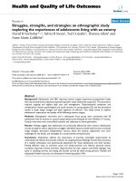
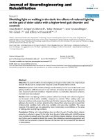
a) The plate with a crack
b) The multi-cracked plate
Figure 1. Geometry of cracked plate with varying thickness according to the first-oder function.
Based on the theories and comparisons of above sections, the cracked rectangular plates
are presented in this section. The plates have one or more cracks (as shown in Fig. 1). The
859
Transport and Communications Science Journal, Vol. 71, Issue 7 (09/2020), 853-867
thickness of plates is according to the first-order function with and the ratio of the crack
length (c/L) is varying from 0.1 to 0.7; the properties of plates are provided in section 3.1.1.
At the edges of the plate, the boundary condition is full simple support (SSSS). The nondimensional free vibration frequency of the plates is defined by Eq. (16).
Table 3. The free vibration frequency parameters of cracked plates with
L=H=0.5m; h 0 =0.025m; h a = h 0 /2 and SSSS.
c/L
0
0.2
0.4
0.6
Inclined
crack ( )
Mode
1
2
3
4
5
-
1.47224 3.59279 3.63005 5.78802 6.92957
00
1.43401 3.56406 3.6209
150
1.4342
300
1.43482 3.56075 3.61538 5.73714 6.70905
450
1.43604 3.56012 3.60921 5.73268 6.76311
600
1.43754 3.60158 3.56303 5.7425
750
1.44051 3.57369 3.59398 3.75886 6.80685
900
1.43938 3.58789 3.57195 5.76517 6.78172
00
1.35719 3.31802 3.59063 5.6159
6.11886
150
1.35605 3.31291 3.58742 5.5613
6.22099
300
1.35434 3.30255 3.57927 5.49011 6.39549
450
1.35565 3.29813 3.57134 5.47624 6.46517
600
1.36106 3.30991 3.56764 5.53235 6.36044
750
1.37631 3.44598 3.56876 5.66773 6.38494
900
1.3696
00
1.28081 2.65944 3.52979 5.21767 5.73978
150
1.27456 2.66753 3.5175
300
1.2619
450
1.25782 2.68542 3.46993 4.95243 6.14677
600
1.27118 2.78237 3.48051 5.03414 5.9492
750
1.32
900
1.29284 2.67201 3.50712 5.14022 5.41946
5.75805 6.63099
3.56295 3.61947 5.7506
3.2977
6.65452
6.79087
3.56679 5.69252 6.03496
5.13433 5.86067
2.66678 3.48855 5.00535 6.05457
3.34583 3.51283 5.50157 6.14798
860
Transport and Communications Science Journal, Vol. 71, Issue 7 (09/2020/), 853-867
In Table 1, the effect of the crack length (c/L) and the slope angle of the crack ( ) on the
frequency of the vibration modes is different. With the increase of the cracked angle :
While the vibration frequency in Mode 5 increases and then decreases, Modes 3 and 4 are
opposite (decrease and then increase); in Modes 1 and 2, the frequency has no clear rule,
Mode 1 increases and then decreases at c/L = 0.2 but decreases and then increases at c/L = 0.4
and c/L = 0.6, Mode 2 decreases and then increases at c/L = 0.2 and c/L = 0.4 but increase and
then decrease at c/L = 0.6. We also found that the larger the ratio of crack length (c/L), the
lower the stiffness of the plate reduces the vibration frequency, which is also shown in Tables
4, 5, 6 and Fig. 2, 3.
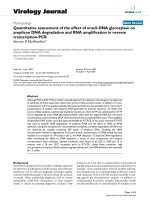
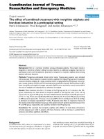
Fig. 2 describes the first shape modes of central-cracked rectangular plate with changing
thickness and cracked angle from 00 to 900.
Figure 2. The first mode shapes of SSSS cracked plates with
L = H = 0.5m; c / L = 0.5; h0 = 0.025m; ha / h 0 = 0.50.
Fig. 3 shows that the vibration frequency decreases as the aspect ratio of the plate (L/H)
increases. This is explained by the fact that when a constant edge (H=0.5m) is made, the
larger the L/H is, the less the plate stiffness is reduced. The vibration frequency of the plate
also decreases in proportion to the decrease in the thickness ratio (ha/h0), (ha/h0 decreases
corresponding to the increase of variable thickness ratio ).
861
Transport and Communications Science Journal, Vol. 71, Issue 7 (09/2020), 853-867
Figure 3. The frequency parameter of cracked plate with change of aspect ratio and thickness ratio.
Table 4 shows the first vibration frequency parameter of the cracked plate (one crack)
with variable thickness and the edges of the plates are full single supported (SSSS) or fully
clamped (CCCC). It is clear that with full single supported boundary condition, the plate
stiffness is smaller than the full clamped and therefore the frequency is also correspondingly
smaller. The plate stiffness also decreases as the thickness ratios (h0/ha) and the crack length
ratio (c/L) increase, causing the frequency to decrease accordingly.
Table 4. The free vibration frequency parameter of cracked plates with different boundary
conditions and L = H = 0.5m; h 0 = 0.025m; = 00.
Boundary
conditions
SSSS
ha / h0
c/L
0
0.1
0.3
0.5
0.7
0.9
1.88401
1.8671
1.77912
1.66969
1.5835
0.8
1.78432
1.76857
1.68616
1.58311
1.50161
0.7
1.68274
1.66827
1.59183
1.49561
1.41906
0.6
1.5789
1.56582
1.49586
1.407
1.33573
0.5
1.47224
1.46069
1.39778
1.31696
1.25138
862
Transport and Communications Science Journal, Vol. 71, Issue 7 (09/2020/), 853-867
CCCC
0.9
3.37417
3.34238
3.18261
3.02511
2.94805
0.8
3.19799
3.16837
3.01837
2.86938
2.79585
0.7
3.01501
2.98788
2.8488
2.709
2.63888
0.6
2.82395
2.79966
2.67284
2.54308
2.47628
0.5
2.62294
2.60189
2.48895
2.37033
2.30678
In tables 5 and 6, the plate has three cracks parallel to the y-axis, the length of cracks c,
spaced d and apart from the edge d0 (Fig. 1).
Table 5. The first frequency parameter of the plates with three cracks and
L = H = 0.5m; h 0 = 0.01m; SSSS.
ha / h0
c/H
d/L
0.9
0.8
0.7
0.6
0.5
0.1
1.80313 1.70814 1.61256
1.51618 1.41859
0.2
1.80006 1.70471 1.60827
1.51051 1.41103
0.3
1.81593 1.71913 1.62075
1.52044 1.41766
0.4
1.83352 1.73592 1.63685
1.5359
0.1
1.67085 1.58395 1.49732
1.41093 1.32465
0.2
1.64669 1.56012 1.47296
1.3851
0.3
1.6561
1.47888
1.38781 1.29453
0.4
1.68053 1.59167 1.50153
1.40963 1.31516
0.1
1.55463 1.47374 1.39293
1.3122
0.2
1.50052 1.42185 1.34239
1.26201 1.18059
0.3
1.47991 1.40201 1.32266
1.24156 1.15824
0.4
1.48806 1.41
1.24926 1.16537
0.2
1.43236
1.29638
0.4
1.5682
1.23151
0.6
1.33054
We see that the first vibration mode of the plates occurs near the center of the plate
(slightly skewed towards the thinner thickness as Fig. 2). Therefore, the more the cracks in the
first mode occur, the lower the frequency is. In Table 5, with d/L= 0.2 (at c/H = 0.2 and
c/H=0.4) and d/L=0.3 (at c/H = 0.6), the plate with the lowest frequency where the cracks are
concentrated (the cracks are located near where the first mode occurred).
863
Transport and Communications Science Journal, Vol. 71, Issue 7 (09/2020), 853-867
Table 6. The first frequency parameter of multi-cracked plates with different boundary conditions
and L = H = 0.5m; h 0 = H / 50; c / L = 0.50.
Boundary
conditions
ha / h0
d/L
0.9
0.8
0.7
0.6
0.5
0.1
0.715312 0.676524 0.636443 0.594771 0.551069
0.2
0.703904 0.665488 0.625531 0.583696 0.539506
0.3
0.724817 0.685
0.4
0.755852 0.714429 0.671157 0.625587 0.577036
0.1
1.25969
1.21907
1.17665
1.13196
1.08424
0.2
1.21396
1.16738
1.11861
1.06728
1.0129
0.3
1.18137
1.13178
1.07995
1.02539
0.967431
0.4
1.15633
1.11055
1.06286
1.01262
0.958782
0.1
1.84462
1.74572
1.64441
1.54023
1.43255
0.2
1.82632
1.72676
1.62286
1.51321
1.39727
0.3
1.73849
1.64598
1.55036
1.45078
1.34581
0.4
1.57965
1.49738
1.41404
1.32927
1.2423
SSFF
0.64334
0.599424 0.552662
CSFF
CCFF
Table 6 describes the frequency parameters of multi-cracked plates with different
boundary conditions. At the edges of the plates, the boundary conditions are described
according to the following rule: The CSFF describes the clamped (C) and simply supported
(S) boundary conditions in the y-direction and the free (F) boundary conditions in the xdirection. We find that the plates with CCFF boundary conditions have the largest stiffness, so
its vibration frequency is also the largest. In contrast, the plates with SSFF boundary
conditions have the smallest frequency. That is understandable, because the bound of the
clamped boundary condition (C) is stronger than the simple supported (S) and the free
boundary condition (F) has no binding of edges.
Fig. 4 describes the first five vibration mode shapes of multi-cracked rectangular plate
with changing the thickness along the length of the plate and different boundary conditions.
864
Transport and Communications Science Journal, Vol. 71, Issue 7 (09/2020/), 853-867
Mode
#1
#2
#3
#4
865
Transport and Communications Science Journal, Vol. 71, Issue 7 (09/2020), 853-867
#5
Figure 4. The first five mode shapes of multi-cracked plates with different boundary conditions
and L = H = 0.5m; h0 = 0.01m; h a / h 0 = 0.5; c / H = 0.5; d / L = 0.30.
4. CONCLUSIONS
This paper is based on the new third-order shear deformation theory, phase field theory
and finite element method to calculate the vibration frequency parameters of cracked
homogeneous plates with the varying thickness. From the detailed numerical results, the
following can be concluded:
➢ The length and number of cracks increase which increases the flexibility in the
plate and hence the frequency decreases.
➢ As the slope of the crack increases, the frequencies can decrease or increase.
➢ The ratio between the two edges of the plate increases, leading to reduction
stiffness of plate, so the vibration frequency decreases.
➢ The smaller the thickness ratio ( ha / h0 ) is, the smaller the frequency is. Especially
with the effect of simultaneous increase of L / H , c / L and h0 / ha the plate
stiffness decreases more, so the vibration frequency decreases rapidly.
➢ The plate with the clamped boundary conditions have a greater stiffness than the
simply supported plate or free plate and the corresponding frequencies is also
greater.
This result will open new potential research of free vibration plates with the propagation
of cracks.
ACKNOWLEDGMENT
This research is funded by University of Transport and Communications (UTC) under grant number
T2020-CB-006.
REFERENCES
[1]. T. Sakiyama, M. Huang, Free vibration analysis of retangular plates with variable thickness,
Journal of Sound and Vibration, 216 (1998) 268–286. />[2]. P. Malekzadeh, G. Karami, Polynomial and harmonic differential quadrature methods for free
vibration of variable thickness thick skew plates, Engineering Structures, 27 (2005) 1563-1574.
866
Transport and Communications Science Journal, Vol. 71, Issue 7 (09/2020/), 853-867
/>[3]. I. Shufrin , M. Eisenberger, Vibration of shear deformable plates with variable thickness – firstorder
and
higher-order
analyses,
J
Sound
Vib,
290
(2006)
465-489.
/>[4]. U.S. Gupta, R. Lal, Seema Sharma, Vibration of non-homogeneous circular Mindlin plates with
variable
thickness,
Journal
of
Sound
and
Vibration,
302
(2007)
1–17.
/>[5]. E. Efraim, M. Eisenberger, Exact vibration analysis of variable thickness thick annular isotropic
and
FGM
plates,
Journal
of
Sound
and
Vibration,
299
(2007)
720-738.
/>[6]. V. Tajeddini, A. Ohadi, M. Sadighi, Three-dimensional free vibration of variable thickness thick
circular and annular isotropic and functionally graded plates on Pasternak foundation, International
Journal of Mechanical Sciences, 53 (2011) 300-308. />[7]. M. Bacciocchi, M. Eisenberger, N. Fantuzzi, F. Tornabene, E. Viola, Vibration analysis of
variable thickness plates and shells by the generalized differential quadrature method, Composite
Structures, 156 (2016) 218-237. />[8]. C.S. Huang, A.W. Leissa, C.W. Chan, Vibrations of rectangular plates with internal cracks or
slits,
International
Journal
of
Mechanical
Sciences,
53
(2011)
436-445.
/>[9]. P.M. Pham, D.V.Thom, D.H. Duc, N.D. Duc, The stability of cracked rectangular plate with
variable thickness using phase field method, Thin-Walled Structures, 129 (2018) 157-165.
/>[10].H.D. Duc, V.D. Thom, P.M. Pham, N.D. Duc, Validation simulation for free vibration and
buckling of cracked Mindlin plates using phase-field method, Mech Adv Mater Struct, 26 (2018)
1018-1027. />[11].P.M. Pham, N.D. Duc, The effect of cracks on the stability of the functionally graded plates with
variable-thickness using HSDT and phase-field theory, Composites Part B: Engineering, 175 (2019)
107086. />[12].P. M. Pham, Anynasys free vibration of the functionally graded material cracked plates with
varying thickness using the phase-field theory, Transport and Communications Science Journal, 70
(2019) 122-131. (in Vietnamese) />[13].G. Shi, A new simple third-order shear deformation theory of plates, International Journal of
Solids and Structures, 44 (2007) 4399-4417. />
867