Control scheme for grid-connected DFIG wind turbine system under grid voltage unbalance
Bạn đang xem bản rút gọn của tài liệu. Xem và tải ngay bản đầy đủ của tài liệu tại đây (676.75 KB, 10 trang )
Journal of Science Technology and Food 20 (2) (2020) 12-21
CONTROL SCHEME FOR GRID-CONNECTED DFIG WIND
TURBINE SYSTEM UNDER GRID VOLTAGE UNBALANCE
Dang Ngoc Khoa1, Van Tan Luong1*, Phan Thi Chieu My2
1
Ho Chi Minh City University of Food Industry
2
Van Hien University
*Email:
Received: 16 February 2020; Accepted: 27 March 2020
ABSTRACT
A novel control scheme for power converters of doubly-fed induction generator (DFIG)
wind turbine system has been proposed to mitigate the current oscillations due to grid
voltage unbalance. With this proposed scheme, the current controller is designed in the
synchronous reference frame and composed of a proportional integral (PI) controller and a
repetitive controller. Thus, the proposed controller gives better performance of the DFIG
wind turbine system, compared with the existing dual PI one. The validity of this control
scheme has been verified by the simulation of the 2MW-DFIG wind turbine system.
Keywords: Current control, doubly-fed induction generator, repetitive control, unbalanced
grid voltage, wind turbine.
1. INTRODUCTION
Nowadays, many speed variable wind turbines with doubly-fed induction generators
(DFIGs), which are connected to the grid through back-to-back converters. For the dynamic
feature, the DFIG becomes the most popular generator for wind power generation system. The
advantage of these facilities is that the power rate of the converters is around 25-30% of the
rated generator power. It has been proven that regulating the electrical power production
within this range will be a good trade-off between optimal operation and costs. Also, DFIG
can supply power to the grid at constant voltage and constant frequency while the rotor can
operate at sub-synchronous mode or super synchronous mode. In addition, the generated
active and reactive power can be controlled independently [1].
The performance of the DFIG wind turbine system under normal conditions is currently
well understood [2, 3]. Practically, both transmission and distribution networks can have
voltage imbalance. Unbalanced voltages cause several drawbacks in the DFIG wind turbine [4].
First, due to the low negative-sequence impedance of a DFIG, high negative-sequence
currents flow in the stator resulting in overcurrents and overheating. Second, a sustained
double-frequency (2ω) pulsation in the electric power and electromagnetic torque is
produced by the interaction of negative-sequence voltages with positive-sequence currents.
These pulsations are not negligible and generate a high stress in the turbine mechanical
system, which can lead to the gearbox fatigue or even to the damage of the rotor shaft,
gearbox, or blade assembly [5]. A wind turbine based on DFIG without unbalanced voltage
control might be disconnected from the grid during the network voltage unbalance [6, 7].
Several different methods have been suggested to control the current of the generator
under unbalanced grid conditions [5, 6, 8-10]. The positive and negative proportionalintegral (PI) current controllers in the synchronous dq-axis known as dual PI controllers have
12
Control scheme for grid-connected DFIG wind turbine system under grid voltage unbalance
been applied in [5, 6, 8, 9], and the proportional resonant (PR) current controller in the
stationary α-β axis have been employed in [10]. However, a simple PR controller is effective
for a specific component. Also, its transfer function becomes much more complicated and a
long execution time is required. On the other hand, it is known that a repetitive control is one
of the specific control schemes for which the objective is to remove the errors due to the
fundamental and high-order components of the periodic inputs. Thus, a repetitive control
strategy is added to the simple PI controller as a compensator for these components.
Simulation results for a 2 MW-DFIG wind turbine system are provided to verify the validity
of the proposed control scheme.
2. EFEECT OF DFIG IN UNBALANCED VOLTAGE
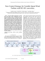
The configuration of the overall system is shown in Figure 1. It consists of a DFIG
wind turbine and back-to-back PWM converters which are connected between the rotor of
DFIG and the grid, whereas the the stator side of DFIG is directly connected to the grid.
DFIG SW3
Wind
Grid
PCC transformer
vs
r
Wind
turbine
Y-Δ
Ps
vg
eg
ir
SW2 Rotor-side
Grid-side
converter
converter
SW1
ig
Vdc
Figure 1. Circuit configuration of DFIG wind turbine system
Figure 2 shows the variable vector F between the s s , r r and dq + , dq − . For a vector
F, the transformations between different reference frames are given as
Fdq+ = Fs e− jet , Fdq− = Fs e jet
(1)
Fdq+ = Fdq− e− j 2et , Fdq− = Fdq+ e j 2et
Fdq+ = Fr e
− j (e −r )t
, Fdq− = Fr e
j ( −e −r )t
where F represents voltage, current and flux.
q+
β
βs
q-
r
d+
e
F
qe
qsl
r
αr
qr
αs
−q e
−e
d
-
Figure 2. Relation between the s s , r r and dq + , dq − reference frames.
13
Dang Ngoc Khoa, Van Tan Luong, Phan Thi Chieu My
During voltage imbalance, the voltage, current, and flux all contain positive- and
negative-sequence components. Based on equation (1) and shown in Figure 2, F can be
expressed in terms of positive- and negative-sequence components in the respective positive
and negative rotating synchronous frames as
Fdq = Fdq+ + Fdq− e− j 2et
(2)
It is desired that the term of the oscillating component (2ωe) in (2) must be eliminated
for safe operation of the grid-connected wind turbine system.
3. CONTROL OF ROTOR-SIDE CONVERTER
The stator-side apparent power under unbalanced grid voltage can be expressed in
terms of the positive and negative sequence components as:
(
)(
j − t −
j − t −
s s*
+
+
S s = 1.5vdqs
idqs = 1.5 e jet vdqs
+ e ( e ) vdqs
e jet idqs
+ e ( e ) idqs
)
*
(3)
= Ps 0 + Psc cos ( 2et ) + Pss sin ( 2et ) + j Qs 0 + Qsc cos ( 2et ) + Qss sin ( 2et )
where Ps0 and Qs0 are the constant (dc) components of the stator active and reactive powers,
whereas Pss, Psc, Qss, and Qsc are the amplitude of the sine and cosine 2ωe oscillation terms of
active and reactive powers, respectively. It is noted that the superscripts of (+), (-), and (∗)
are used to indicate a positive sequence, negative sequence, and conjugated value,
respectively.
Similarly, the electromagnetic torque is obtained as [6]
Te ( t ) = Te 0 + Tec cos ( 2et ) + Tes sin ( 2et )
(4)
Expanding the current and voltage vectors in (3) and (4), the following relations are
obtained:
Ps 0 = 1,5(vds+ ids+ + vqs+ iqs+ + vds− ids− + vqs− iqs− )
+ −
Psc = 1,5(vds
ids + vqs+ iqs− + vds− ids+ + vqs− iqs+ )
− +
Pss = 1,5(vqs
ids − vds− iqs+ − vqs+ ids− + vds+ iqs− )
+ +
Qs 0 = 1,5(vqs
ids − vds+ iqs+ + vqs− ids− − vds− iqs− )
Qsc = 1,5(v+qs ids− − vds+ iqs− + vqs− ids+ − vds− iqs+ )
+ −
Qss = 1,5(vds
ids + vqs+ iqs− − vds− ids+ − vqs− iqs+ )
It can be seen from (4) that the generator torque due to the grid voltage unbalance
includes the dc component (Te0) and ac components (Tec, Tes) which have the double
frequency (2ωe) of the grid. In order to eliminate the 2ωe oscillations in the electromagnetic
torque, its oscillating terms in (4) must be nullified (Tec = Tes =0). To achieve this, the
oscillating components of the reactive powers (Qsc, Qss) must be controlled to be zero. The
reference of the DFIG active power ( Ps*0 ) is obtained from a maximum power point tracking
(MPPT) algorithm [11]. The reference reactive power ( Qs*0 ) injected by the DFIG can be
calculated according to the grid code requirement.
14
Control scheme for grid-connected DFIG wind turbine system under grid voltage unbalance
Figure 3 shows the control block diagram of the rotor-side converter under unbalanced
grid voltage, which consists of an outer power control loop and an inner current control loop.
As for the first loop, the active power is controlled to deliver the generated power from the
generator to the grid and the the reactive power (Qs0) is controlled to be zero. The latter loop
one allows to regulate the rotor currents for the reduction of the torque oscillation, regardless
of the unbalanced grid voltages, based on the PI-repetitive controller.
Grid
Positive and negative
sequence extraction
DFIG
DFIG
r
+
i dqs
i dqs
+
vdqs
vdqs
Positive and
negative sequence
extraction
vqr*
PI-Repetitive
controller
-
abc
+
Rotor-side
converter
PWM
PI-Repetitive
controller
i dr*
i qr*
+
vdr
dq
idqr
+
iar
i
+
ibr
+
dqr
i
+*
qr
abc
dq +
i qr i dr
Vdc
i +*
dr
+
+
Encoder
+
q sl
Ps0*
MPPT
r
Power
controller Qs0* =0
dq abc
-*
i dr
i
-*
qr
Power
controller
Qsc* =0
Qss*=0
q sl-
Figure 3. Control diagram of rotor-side converter under unbalance grid voltage.
Bode Diagram
f0
2f0
Frequency (Hz)
Figure 4. Bode plots for the PI and PI-Repetitive controllers.
In order to investigate the superior characteristics of the PI-Repetitive controller
(proposed controller) over the PI controller (conventional controller), Figure 4 describes
closed-loop Bode diagram for the conventional controller and the proposed controller given
in (5) and (6), respectively.
15
Dang Ngoc Khoa, Van Tan Luong, Phan Thi Chieu My
GPI ( s ) = k p +
ki
s
(5)
GPI −Re petitive ( s) = k p +
ki
e−Ts
+ kre
s
1 − e−Ts
(6)
As shown in Figure 4, the PI-Repetitive controller designed in the synchronous
reference frame produces very high peak gains at the frequencies of 120 Hz, 180 Hz, etc. In
this research, the frequency of 120 Hz is mainly considered for the rotor current controller of
the DFIG since the oscillating components (2ωe) are included in the generator torque and
power under the unbalanced grid voltage. Thus, the proposed current controller can
sufficiently compensate the double frequency components caused by unbalanced grid
voltage and it can guarantee a good quality of the generator current despite the unbalanced
grid voltage.
4. CONTROL OF GRID-SIDE CONVERTER
The apparent power injected by the grid-side converter to the grid can be partitioned as
follows [12, 13]:
(
s
s*
+
S g = 1.5vdqs
igdqs
= 1.5 e jet vdqs
+e
j ( −e )t −
dqs
v
) (e
jet +
gdqs
i
+e
j ( −e )t −
gdqs
i
)
*
= Pg 0 + Pgc cos ( 2et ) + Pgs sin ( 2et ) + j Qg 0 + Qgc cos ( 2et ) + Qgs sin ( 2et )
(7)
where Pg0 and Qg0 are the constant (dc) components of the grid active and reactive
powers, whereas Pgs, Pgc, Qgs, and Qgc are the amplitude of the sine and cosine 2ωe oscillation
terms of active and reactive powers, respectively.
From (7), the powers (Pg0, Qg0, Pgc, Pgs) can be represented in a matrix form as
+
vds
Pg 0
+
vqs
Qg 0
=
1.5
P
−
vqs
gs
Pgc
−
vds
+
vqs
−
vds
+
−vds
−
vqs
−
−vds
+
−vqs
−
vqs
+
vds
− +
vqs
igd
− +
−vds
igq
+ −
vds igd
+ −
vqs
igq
(8)
The second-order components of power (Pgs, Pgc) due to the unbalanced grid voltage
fluctuates not only the DC-link capacitor power but also the real power delivered to the grid.
These two components are controlled to zero to eliminate the power fluctuations. The real
power reference ( Pg*0 ) is the product of the dc voltage controller output and the dc voltage
reference. Thus, the positive- and negative-sequence components of the current references
are expressed as
+*
+
igd
vds
+*
+
igq
2 vqs
=
−*
−
3 vqs
igd
−*
−
igq
vds
+
vqs
−
vds
+
−vds
−
vqs
−
−vds
+
−vqs
−
vqs
+
vds
−
vqs
−
−vds
+
vds
+
vqs
−1
Pg*0
Qg* 0
0
0
(9)
Figure 5 shows the control block diagram of the grid-side converter under unbalanced
grid voltage, which consists of an outer DC-link voltage control loop and an inner current
control loop. The dq-axis current controller is employed as in the rotor-side converter, which
depend on the PI-repetitive control method.
16
Control scheme for grid-connected DFIG wind turbine system under grid voltage unbalance
Grid
DFIG
DFIG
Positive and
negative sequence
extraction
+
q-
abc
dq+
i gq
i gd
PI-Repetitive
controller
PI-Repetitive
controller
-
+
dq abc
+
+
Current
+
Qg0* =0 reference i gq
−
calculation
i
Pgs*=0 from (9) gd
−
i gq
*
Pgc =0
i gd
+
+
i gd
+
DC-link P *
g0
voltage
controller
-
Vdc*
,q +,q -
vd
dq
vq*
abc
Grid- side
converter
PWM
i gq
q+
Figure 5. Control diagram of grid-side converter under unbalance grid voltage.
5. SIMULATION RESULTS
To verify the feasibility of the proposed method, PSCAD simulation has been carried
out for a 2 MW-DFIG wind turbine system. For the wind turbine: R = 44 m; ρ = 1.225 kg/m3;
λopt = 8; Jt = 5.67x10⁶ kgm2. For the DFIG: the grid voltage is 690 V/60 Hz; the rated power
is 2 MW; Rs = 0.00488 pu; Rr = 0.00549 pu; Lls = 0.0924 pu; Llr = 0.0995 pu; and Jg = 200 kgm2.
For 2 MW-DFIG system, 14% unbalanced voltage sag is applied at the grid side for investigation.
Figure 6 shows the control performance of the DFIG at the rotor-side converter for a
grid unbalanced voltage sag. The wind speed is assumed to be constant (10.5 m/s) since the
pattern of variable wind speed can not produce a remarkable effect during the short time
duration of the fault. The fault condition is 14% sag in the grid A-phase voltage for 0.5 s
which is between 1.5 s and 2 s.
Figure 6A shows the performance of the DFIG using dual PI control method for the
rotor currents, in case of the unbalanced grid condition [6]. As can be seen from Figure
6A(b), the oscillations of the dq-axis positive-sequence rotor currents become large.
Similarly, the stator active and reactive powers, the generator torque as illustrated in Figure
6A(c), (d) and (f), respectively contain the significant pulsations at 120 Hz. As shown in
Figure 6A(e), the generator speed is much oscillated during the grid fault.
Figure 6B shows the DFIG performance using the proposed control method for the
rotor currents under the grid fault condition. With the current control based on PI-Repetitive
controller, the oscillations of the positive-sequence rotor currents in dq-axis, as shown in
Figure 6B(b) are significantly suppressed. Accordingly, the stator active and reactive power
oscillations are also mitigated, as shown in Figure 6B(c) and Figure 6B(d), respectively.
Also, the oscillations of the generator speed and torque are considerably reduced, as shown
in Figure 6B(e) and (f), respectively. By comparison, the rotor current control method based
on PI-Repetitive controller gives less oscillations than dual PI controller.
17
Dang Ngoc Khoa, Van Tan Luong, Phan Thi Chieu My
(A) Dual PI controller
(B) PI - Repetitive controller
(a)Grid voltage(V)
(a)Grid voltage(V)
Fault duration
Fault duration
(b) Rotor current in dq-axis (kA)
(b) Positive- sequence rotor current in dq-axis (kA)
i+
dr
i
i dr
+
i dr
+
qr
i dr
i
+
i qr
qr
i qr
(c) Stator active power (MW)
(c) Stator active power (MW)
Ps
Ps0
Ps
Ps
(d) Stator reactive power (kVAr)
(d) Stator reactive power (kVAr)
Q s
Qs0
Qs
(e) Generator speed (rpm)
Qs
(e) Generator speed (rpm)
r
r
(f) Generator torque (pu)
(f) Generator torque (pu)
Tg
Tg
Time (s)
Time (s)
Figure 6. Control performance of rotor-side converter for grid phase-A voltage sag (14%) in 2 cases:
(A) Dual PI control [6]. (B) Proposed method. (a) Grid voltage. (b) Rotor current. (c) Stator active
power. (d) Stator reactive power. (e) Generator speed. (f) Generator torque.
18
Control scheme for grid-connected DFIG wind turbine system under grid voltage unbalance
Figure 7 shows the control performance of the DFIG at the grid-side converter for 14%
grid A-phase voltage sag. Figure 7A and 7B show the performance of the DFIG using dual
PI control method (see [6]) and PI-Repetitive control one for the grid currents, respectively.
As can be clearly seen in Figure 7A(b), the DC-link voltage is controlled to follow its
reference well. However, the oscillations of the DC-link voltage is high and its variation is
12.5%, compared with the reference DC-link voltage. Likewise, the oscillations of the
positive-sequence rotor currents in dq-axis, as shown in Figure 7A(c) are also increased. By
applying the PI-Repetitive controller for grid currents, the DC-link voltage and grid current
oscillations are significantly reduced, as shown in Figure 7B(b) and (c), respectively. By
comparison, the grid current control method based on PI-Repetitive controller gives better
performance, compared with dual PI controller.
(A) Dual PI controller
(B) PI - Repetitive controller
(a)Grid voltage(V)
(a)Grid voltage(V)
Fault duration
Fault duration
(b) DC-link voltage (kV)
(b) DC-link voltage (kV)
(c) Grid currents (A)
(c) Positive- sequence grid currents in dq-axis (A)
+
i gq
+
i gq
i gq
i gd
i gd+
+
i gd
i gq
i gd
Time (s)
Time (s)
Figure 7. Control performance of grid-side converter for grid phase-A voltage sag (14%) in 2 cases:
(A) Dual PI control [6]. (B) Proposed method. (a) Grid voltage. (b) DC-link voltage. (c) Grid current.
6. CONCLUSION
This paper has presented a current control scheme based on the PI-Repetitive
controllers for grid-connected DFIG wind turbine system under unbalanced grid conditions.
The dynamic response of controlling the DFIG to the transient grid unbalance has been
analyzed and the current control scheme for both grid-side converter and rotor-side converter
has been introduced. Compared with the existing unbalanced control method like dual PI
control, the proposed one provides better performances for both grid and rotor currents, from
which the generator torque and power oscillations are much reduced. The validity of the
proposed one is verified by the simulation results for the 2 MW-DFIG wind turbine system
under unbalanced grid voltage conditions.
19
Dang Ngoc Khoa, Van Tan Luong, Phan Thi Chieu My
REFERENCES
1. Akhmatov V. - Analysis of dynamic behavior of electric power systems with large
amount of wind power, Ph.D. dissertation, Department of Electrical Power
Engineering, Technical University of Denmark, Kongens Lyngby, Denmark (2003).
2. Pena R., Clare J. C., and Asher G. M. - Double fed induction generator using backto-back PWM converter and its application to variable- speed wind-energy
generation, IEE Proceedings on Electric Power Applications 143 (3) (1996) 231-241.
3. Yamamoto M. and Motoyoshi O. - Active and reactive power control for doubly-fed
wound rotor induction generator, IEEE Transactions on Power Electronics 6 (4)
(1991) 624-629.
4. Xu L. and Wang Y. - Dynamic modeling and control of DFIG-based wind turbines
under unbalanced network conditions, IEEE Transactions on Power Systems 22 (1)
(2007) 314-323.
5. Brekken T. K. and Mohan N. - Control of a doubly fed induction generator under
unbalanced grid voltage conditions, IEEE Transactions on Energy Conversion 22 (1)
(2007) 129-135.
6. Abo-Khalil A. G., Lee D.-C., and Jang J.-I. - Control of back-to-back PWM
converters for DFIG wind turbine systems under unbalanced grid voltage, IEEE
International Symposium on Industrial Electronics (2007) 2637-2642.
7. Joshi N. and Mohan N. - A novel scheme to connect wind turbines to the power grid,
IEEE Transactions on Energy Conversion 24 (2) (2009) 504-510.
8. Lopez J., Gubia E., Sanchis P., Roboam X., and Marroyo L. - Wind turbines based
on doubly fed induction generator under asymmetrical voltage dips, IEEE
Transactions on Energy Conversion 23 (1) (2008) 321-330.
9. Lun Yan, Xiaoming Yuan - Positive and negative sequence control of DFIG based
wind turbines and its impact on grid voltage profile concerning converter control
capability, The Journal of Engineering 2017 (13) (2017) 1584-1589.
10. Hu J., He Y., and Wang H. - Adaptive rotor current control for wind turbine driven
DFIG using resonant controllers in a rotor rotating reference frame, J. Zhejiang
Univ. Sci. A 9 (2) (2008) 149-155.
11. Kim K.-H., Van T. L., Lee D.-C., Song S.-H., and Kim E.-H. - Maximum Output
Power Tracking Control in Variable-Speed Wind Turbine Systems Considering
Rotor Inertial Power, IEEE Transactions on Industrial Electronics 60 (8) (2013)
3207-3217.
12. Kim K.-H., Jeung Y.-C., Lee D.-C., and Kim H.-G. - LVRT Scheme of PMSG Wind
Power Systems Based on Feedback Linearization 27 (5) (2012) 2376-2384.
13. Van T. L., Nguyen T. D., Tran T. T., and Nguyen H. D. - Advanced control strategy
of back-to-back PWM converter in PMSG wind turbine system, Advances in
Electrical and Electronic Enginering (AEEE) - Power Enginering and Electrical
Enginering 13 (2) (2015) 81-95.
20
Control scheme for grid-connected DFIG wind turbine system under grid voltage unbalance
TÓM TẮT
CHIẾN LƯỢC ĐIỀU KHIỂN KẾT NỐI LƯỚI CỦA HỆ THỐNG TUA-BIN GIÓ
DÙNG MÁY PHÁT DFIG KHI ĐIỆN ÁP LƯỚI KHÔNG CÂN BẰNG
Đặng Ngọc Khoa1, Văn Tấn Lượng1,*, Phan Thị Chiêu Mỹ2
1
Trường Đại học Công nghiệp Thực phẩm TP.HCM
2
Trường Đại học Văn Hiến
*Email:
Chiến lược điều khiển các bộ chuyển đổi công suất của hệ thống tua-bin gió dùng máy
phát không đồng bộ nguồn kép (DFIG) được đề xuất để giảm thiểu độ dao động dòng điện
do sự không cân bằng điện áp lưới gây ra. Bộ điều khiển dòng điện được thiết kế trong hệ
tọa độ xoay và bao gồm bộ điều khiển tích phân - tỷ lệ (PI) và bộ điều khiển lặp lại. Do đó,
bộ điều khiển đề xuất cho kết quả vận hành tốt hơn cho hệ thống tua-bin gió dùng máy phát
DFIG, so với bộ điều khiển PI kép hiện có. Tính hợp lý của chiến lược điều khiển này đã
được xác minh bằng kết quả mô phỏng hệ thống tua-bin gió 2MW-DFIG.
Từ khóa: Điều khiển dòng điện, máy phát không đồng bộ nguồn kép, điều khiển lặp lại, điện
áp lưới không cân bằng, tua-bin gió.
21