Light—Science & Magic- P4
Bạn đang xem bản rút gọn của tài liệu. Xem và tải ngay bản đầy đủ của tài liệu tại đây (8.29 MB, 50 trang )
LIGHT—SCIENCE & MAGIC
138
no light. Together, these facts suggest that the front of the
metal cannot be lit.
However, we have also said that the black plastic is glossy.
And we know that glossy things do produce direct reflection,
even if they are too black to produce diffuse reflection. This
means that we can light the metal by bouncing light off the
plastic surface as in Figure 6.27.
If you examine the angles, you see that a light under the
camera can bounce light from the glossy plastic to the metal.
That light strikes the metal at such an angle that it then reflects
back to the camera to record on film. The metal is lit, and the
bright metal in Figure 6.28 proves it. As far as the metal can
tell, it is being lit by the plastic surface in the scene. However,
the camera cannot see that light is reflecting from the black
plastic; the family of angles defined by the plastic makes it
impossible.
Like the earlier glass surface, the acrylic surface will reflect
the overhead light source. Once again, we used a polarizing fil-
ter on the lens to eliminate the glare.
Finally, notice that the front of the box now shows a texture
not seen in the earlier examples. This is because invisible light
is only effective in a small area on the tabletop. When metal is
not absolutely flat, the family of angles required to light it
6.26
The same scene as in
Figure 6.24, but with a lens
polarizer removing reflection
from the glass. The polarizer
does not affect the metal.
Hunter-Ch06.qxd 10:1:07 6-44 AM Page 138
Please purchase PDF Split-Merge on www.verypdf.com to remove this watermark.
METAL
139
Glossy Black Acrylic
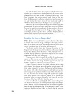
6.27
“Invisible” light reflected
from the glossy black plastic
lights the metal. No light reflects
directly from the plastic to the
camera, so the camera cannot
see the light source for the
metal.
6.28
The result of “invisible”
light. The light source for the
box is in the scene—the black
plastic directly in front of it.
Hunter-Ch06.qxd 10:1:07 6-44 AM Page 139
Please purchase PDF Split-Merge on www.verypdf.com to remove this watermark.
LIGHT—SCIENCE & MAGIC
140
becomes larger. Next we’ll examine an extreme example of that
circumstance.
ROUND METAL
Lighting a round piece of metal begins, like any other metal
shape, with an analysis of the family of angles that produces
direct reflection. Unlike any other metal shape, the family of
angles defined by a piece of round metal includes practically
the whole world!
Figure 6.29 shows the relevant family of angles for a
camera photographing a round metal object at a typical view-
ing distance. Remember, lighting metal requires the prepara-
tion of a suitable environment. Round metal requires a lot
more work to light because it reflects so much more of that
environment.
Notice that the camera will always be in that environment
seen by the metal. There are no view-camera tricks to remove
the camera from the family of angles reflected by round metal.
Furthermore, the reflection of the camera will always fall
exactly in the center of the metal subject, where it is most
noticeable to the viewer.
For this exercise we will use the most difficult example possi-
ble: a perfectly smooth sphere. Figure 6.30 shows the problem.
Round Metal
F
a
m
i
l
y
o
f
A
n
g
l
e
s
6.29
The family of angles for a
round metal subject includes the
whole environment, including
the camera.
Hunter-Ch06.qxd 10:1:07 6-44 AM Page 140
Please purchase PDF Split-Merge on www.verypdf.com to remove this watermark.
METAL
141
The first step in fixing this problem would be to get rid of
unnecessary objects. However, the camera is the one offend-
ing object that no cleanup effort can remove. There are three
ways to eliminate the camera reflection: we can camouflage
the reflection, keep the camera in the dark, or put the subject
in a tent.
Camouflage
For our purposes, camouflage is any desirable clutter that helps
make unwanted reflections less obvious. Sometimes the subject
provides its own camouflage. If the surface is irregular, the
camera reflection may fall between the cracks.
Additional subjects in the scene can also provide camou-
flage. The reflection of surrounding subjects in the metal can
break up other reflections that we do not want the viewer to
see. If the surrounding objects in Figure 6.30 were items
appropriate to the scene, instead of studio tools, they could
make good camouflage. Small subjects can be put directly on
top of a reflection of a larger one.
Keeping the Light off the Camera
If the camera is kept in the dark, then it cannot see itself
reflected in the subject. Whenever possible, confine the
6.30
The common problem
presented by round metal.
Hunter-Ch06.qxd 10:1:07 6-44 AM Page 141
Please purchase PDF Split-Merge on www.verypdf.com to remove this watermark.
LIGHT—SCIENCE & MAGIC
142
lighting to the subject. Long lenses help. A camera farther from
the subject is less likely to have extraneous light falling on it.
If it is impossible to keep the light off the camera, covering
it with black material can work as well. A few pieces of black
tape could have covered the bright parts of the camera in
Figure 6.30. Black cloth or a black card with a hole in it can
conceal the camera entirely.
However, this works only in a studio large enough that the
surrounding walls do not reflect. In a smaller room, building a
tent may be the only solution.
Using a Tent
A tent is a white enclosure that serves as both the environment
and the light source for the subject. The subject goes inside the
tent and the camera is almost always outside, looking in
through a small opening. Tents are often used for subjects such
as metal, which produce a great deal of direct reflection, but
they are sometimes used simply to produce very soft light for
such subjects as scientific specimens and for fashion and
beauty.
A tent can be made of opaque white material such as a col-
lection of reflector cards. Then we can put the lights in the tent
and bounce them off the inside walls. This produces a very soft
light, but the lights themselves reflect visibly in any mirror-like
subject. More often we use translucent material such as frosted
plastic and project the lights through the tent wall.
An ideal tent would be a translucent white dome with no
visible seams. Most photographers approximate this ideal as
closely as possible with translucent paper or plastic. Figure 6.31
shows one way to do this.
We do not show any lights other than the soft box that is a
structural part of this tent. Additional lights are almost always
useful, but their exact positions and sizes are highly optional.
Some photographers like to light the whole tent uniformly,
whereas others tend to light only a few small areas.
Figure 6.32 was shot in such a tent. This photograph is a
good example of the principle, but a bad picture. The lighting
on the ball is acceptable, except for the dark spot in the middle,
which is the hole through which the camera is seeing.
One of the authors once made a picture similar to this for
the cover of a department store Christmas catalog. But the
peripheral areas also included bits of ribbon and greenery to
Hunter-Ch06.qxd 10:1:07 6-44 AM Page 142
Please purchase PDF Split-Merge on www.verypdf.com to remove this watermark.
METAL
143
camouflage the seams in the tent. Looping a piece of the rib-
bon “accidentally” across the front of the ball hid the camera. If
the intent of the image had precluded additional subject mat-
ter to use for camouflage, the only remedy to the problem
would have been retouching.
Round Metal
Seamless
Background
Diffusion
Material
6.31
Building a tent around
the subject and shooting
through a hole in it is one way of
cutting down on unwanted
reflections on shiny round
subjects.
6.32
A photograph of a shiny
round subject shot with the help
of a tent such as the one
diagrammed in the previous
figure. By itself, the tent does
not solve the problem, but it is a
start. Camouflage would
complete the setup.
Hunter-Ch06.qxd 10:1:07 6-44 AM Page 143
Please purchase PDF Split-Merge on www.verypdf.com to remove this watermark.
LIGHT—SCIENCE & MAGIC
144
It is tempting to build a very large tent to keep the camera
as far from the subject as possible. Intuitively we know that if
the camera is farther from a metal subject, then the reflection
of the camera will be smaller. However, the image of the sub-
ject also becomes smaller, so we have to shoot with a longer
lens. But this “remedy” also enlarges the reflection of the cam-
era back to its original size! The camera itself is the only reflec-
tion whose size cannot be reduced by moving it farther away. It
always remains constant, relative to the subject. Resist the
temptation; the extra work is always wasted.
OTHER RESOURCES
The basic approach to lighting metal is determined by the fam-
ily of angles and, therefore, by the shape of the metal. Beyond
the basic lighting, there are a few more techniques you may
want to try at any time with any piece of metal.
Any of these additional options can be purely creative deci-
sions, but they can serve technical purposes too. For example,
you may find that the edge of a piece of metal is disappearing
into the background. Keep in mind, the closer the metal
comes to producing pure direct reflection, the closer that
reflection comes to photographing at the same brightness as
the light source. As we have seen, the surface on which the
metal is sitting is often the light source. If they are of identical
brightness, the camera cannot see where one surface ends and
the other begins. This is a case where polarizing filters, “black
magic,” or dulling spray can add the finishing touches to the
lighting.
Polarizing Filters
Metal does not produce polarized direct reflections. Therefore,
we cannot usually use a lens polarizer alone to block the direct
reflections coming from metal. Remember, however, that the
light source may have some polarized rays. If so, they remain
polarized as they reflect from the metal. This is frequently the
case if the metal is reflecting blue sky. In the studio, the light
reflected from the surface on which the metal rests is often
partly polarized. In either case, a polarizer on the lens gives
additional control over the brightness of the metal. Even if
there is no polarized light in the scene, we can put it there by
using a polarizing filter over the light.
Hunter-Ch06.qxd 10:1:07 6-44 AM Page 144
Please purchase PDF Split-Merge on www.verypdf.com to remove this watermark.
METAL
145
Black Magic
Black magic is anything added to the basic lighting setup solely
to place a black “reflection” in the metal surface. Black
reflected in an edge can help to differentiate it from the back-
ground. Reflected across the center of a slightly irregular
surface, black magic can also add dimension.
Black magic usually involves the use of a gobo. This works
especially well with a diffusion sheet. Placing the gobo between
the diffusion sheet and the subject makes a hard black reflec-
tion. Putting it on the other side of the diffusion sheet from the
subject creates a softly graduated reflection. The farther behind
the diffusion sheet you place the gobo, the softer it becomes.
Occasionally you may decide to use an opaque reflector
(reflecting another light somewhere else in the set) as a light
source for the metal. In this case, a gobo cannot produce softly
graduated black magic, but a soft-edged stripe of black spray
paint across the reflector will create the same effect.
Beware of Blue Highlights
Polarizing both the lights and the lens may create special problems if the photo-
graph is color and the subject is metal. Polarizing filters allow more light from the
blue end of the spectrum to pass through than from the red. This makes such a
filter behave like a very light blue filter. The effect is so slight that we do not notice
the color imbalance in a color photograph unless extremely accurate color rendi-
tion is necessary.
Even when there are polarizing filters on both the lens and the lights, the
increased blue shift is rarely a problem if the subject is one that produces mostly
diffuse reflection. However, if the subject produces much direct reflection, some
of the highlights may be offensively blue. Furthermore, because the blue occurs
only in the highlights, they can’t be fixed by general color correction.
It is easy to overlook these blue highlights if you do not anticipate them, so
be warned. If they happen, and you decide the sacrifice is worthwhile, budget the
time for retouching.
Dulling Spray
Dulling spray creates a matte surface that increases the diffuse
reflection and decreases the direct reflection from a piece of
metal. This allows a little more freedom to light the metal with-
out strictly obeying the limitations imposed by the family of
angles. Unfortunately, metal with dulling spray on it no longer
looks brightly polished and may not even look like metal any
longer!
Hunter-Ch06.qxd 10:1:07 6-44 AM Page 145
Please purchase PDF Split-Merge on www.verypdf.com to remove this watermark.
LIGHT—SCIENCE & MAGIC
146
Heavy-handed use of dulling spray is a habit to avoid. To an
educated eye, it reveals, rather than conceals, a photographer’s
inability to light metal well. With that said, we should also
admit that all of the authors of this book keep dulling spray
handy in their studios.
Try to light the metal as well as possible. Then, if necessary,
add a little dulling spray just to an overly bright highlight or a
disappearing edge. Keep as much of the gleam of the metal as
you can, and avoid thickly coating the entire surface.
WHERE ELSE DO THESE TECHNIQUES APPLY?
The techniques we use for metal are good to remember any
time direct reflection is important. We will see more of them in
the rest of this book. Some of these applications may not be
obvious yet. For example, we will see in Chapter 9 why much
of the technique for lighting metal is useful for almost any
black-on-black subject, regardless of the material of which it is
made.
Other subjects that produce direct reflection are readily
apparent. One of them is glass. Glass, however, offers some
additional opportunities and challenges of its own. We will see
why in the next chapter.
Hunter-Ch06.qxd 10:1:07 6-44 AM Page 146
Please purchase PDF Split-Merge on www.verypdf.com to remove this watermark.
Hunter-Ch06.qxd 10:1:07 6-44 AM Page 147
Please purchase PDF Split-Merge on www.verypdf.com to remove this watermark.
148
Hunter-Ch07.qxd 10:1:07 6-53 AM Page 148
Please purchase PDF Split-Merge on www.verypdf.com to remove this watermark.
4
4.1
Figure legend using
dummy text to show the style
7
The Case of the
Disappearing Glass
The distant genius who first fused sand into glass has tricked
the eyes and delighted the brains of every generation of
humans to follow. It has perhaps also grayed the hair and
wasted the time of more photographers than any other sub-
stance. However, attempting to reproduce the appearance of
glass need not lead to the photographic disasters we so often
see. This chapter will discuss the principles, the problems, and
some straightforward solutions to the basic challenges that glass
offers.
THE PRINCIPLES
The appearance of glass is determined by many of the same
principles we discussed in the preceding chapter on metal. Like
metal, almost all reflection produced by glass is direct reflec-
tion. Unlike metal, however, this direct reflection is often polar-
ized. We might expect the techniques used for lighting glass to
be similar to those used for metal. We might find a polarizing
filter useful more often, but otherwise apply the same methods.
However, this is not so. When we light metal, we are prima-
rily interested in the surfaces facing the camera. If they look
right, then minor adjustments can usually take care of the
details. Lighting glass, however, requires attention to the edges.
If the edges are clearly defined, we can often ignore the front
surface altogether.
149
Hunter-Ch07.qxd 10:1:07 6-53 AM Page 149
Please purchase PDF Split-Merge on www.verypdf.com to remove this watermark.
LIGHT—SCIENCE & MAGIC
150
THE PROBLEMS
The problems caused by glassware are a result of the very
nature of the material. It is transparent. From most angles, light
striking the visible edge of a piece of glassware does not reflect
in the direction of the viewer. Such an edge is invisible. An
invisible glass has no shape or form. To make matters worse,
the few tiny reflections we do see are often too small and too
bright to tell the anything about surface detail or texture.
Figure 7.1 shows both problems. The direct reflections of
the lights illuminating the scene do nothing but distract from
the composition. They are not adequate to define the surface of
the glass.
The lack of a clearly defined form is an even more serious
problem. With no clear outlines and no marked differences in
edge tonality, the glass merges with the background.
THE SOLUTIONS
Having seen what does not work, look now at Figure 7.2.
Compare the visibility of the glass shown in it with that shown
7.1
The problems with this
picture are caused by the nature
of the glass from which the
subjects are made. The glass is
both transparent and highly
reflective.
Hunter-Ch07.qxd 10:1:07 6-54 AM Page 150
Please purchase PDF Split-Merge on www.verypdf.com to remove this watermark.
THE CASE OF THE DISAPPEARING GLASS
151
in the earlier photograph. Both photographs show the same
glassware and the same background, and both are made from
the same viewpoint with the same lens. As you can see, how-
ever, the difference is dramatic.
In the second photograph, strong black lines delineate the
shape of the glass. No distracting reflections mar the surface.
By comparing these two photographs, we can list our objectives
in glassware photography. If we want to produce a picture that
clearly and pleasingly reproduces the glassware, we must do the
following:
1. Produce strong lines along the edges of the subject.
These lines delineate its shape and set it apart from the
background.
2. Eliminate distracting reflections of the lights and other
equipment we are using.
Let’s look at some of the specific ways we can accomplish
these objectives. We will begin by looking at some “ideal”
shooting situations. These will help us demonstrate the basic
techniques. Later, we will have to go beyond those basics to
7.2
Good edge definition is
essential to lighting glass.
Hunter-Ch07.qxd 10:1:07 6-54 AM Page 151
Please purchase PDF Split-Merge on www.verypdf.com to remove this watermark.
LIGHT—SCIENCE & MAGIC
152
overcome problems that arise whenever nonglass objects are in
the same scene. We will begin by talking about our first objec-
tive, edge definition.
TWO ATTRACTIVE OPPOSITES
We can avoid almost all the problems associated with edge def-
inition by using one of two basic lighting arrangements. We will
call these the bright-field and the dark-field methods. We could
also call them dark-on-light and light-on-dark approaches. The
results of these two are as opposite as the terms imply, but we
will see that the principles guiding them are identical. Both
methods produce the strong tonal differences between the sub-
ject and the background that delineate edges to define the
shape of glassware.
Bright-Field Lighting
Figure 7.2 is an example of the bright-field approach to lighting
glass. The background dictates how we must treat any glass
subject. On a bright background, we have to keep the glass dark
if it is to remain visible.
If you have read Chapter 2 and the chapters following it,
you have already guessed that the bright-field method requires
eliminating all direct reflection from the edge of the glass sur-
face. You also should be able to see why we need to begin this
discussion by examining the family of angles that determines
direct reflection from this particular subject.
Look at Figure 7.3, a bird’s-eye view of the family of angles
that can produce direct reflection on a single round glass. We
could draw a similar diagram for each piece of glassware in our
example photograph.
The family of angles in this diagram is similar to that defined
by round metal in the last chapter. This time, however, we are
not interested in most of that family. For now, we care only
about the extreme limits of the family of angles, labeled L in
the diagram. Light from these two angles determines the
appearance of the edge of the glass. These limits tell us where
the light must be if the edges of the glass are to be bright in the
pictures or, conversely, where it must not be if the edges are to
remain dark. Because in the bright-field approach we do not
want the edge of the glass to be bright in the photograph, there
must be no light along the lines marked L in the diagram.
Hunter-Ch07.qxd 10:1:07 6-54 AM Page 152
Please purchase PDF Split-Merge on www.verypdf.com to remove this watermark.
THE CASE OF THE DISAPPEARING GLASS
153
Figure 7.4 illustrates one good way to produce a bright-field
glass photograph. It is not the only way, but it is a good exercise
that we suggest you try if you have not done it before. Look at
the way the light behaves in each step. This will make it easy to
predict what will work and what will not in any variation on this
arrangement you decide to try in the future.
These steps work best in the listed sequence. Notice that we
do not bother to put the subject into the scene until near the
end of the process.
1. Choose the background. Begin by setting up a light-
toned background. We can use any convenient material.
Translucent materials such as tracing paper, cloth, and plas-
tic shower curtains are a few good materials to try. We might
also use opaque surfaces, such as light-toned walls, card-
board, or foamcore.
2. Position the light. Now, place a light so that it illuminates
the background evenly. Figure 7.4 shows two possible ways
to accomplish this; both can produce identical results.
Usually the photographer uses one or the other, rarely
both.
F
a
m
i
l
y
o
f
A
n
g
l
e
s
Glass Subject
L
L
7.3
The limits of the family of
angles in this diagram are
marked by L. Light from these
two points determines the
appearance of the edge of the
glass.
Hunter-Ch07.qxd 10:1:07 6-54 AM Page 153
Please purchase PDF Split-Merge on www.verypdf.com to remove this watermark.
LIGHT—SCIENCE & MAGIC
154
Figure 7.2 was shot using a light behind translucent
paper. This is a particularly convenient setup because it
keeps the work space around both the camera and the sub-
ject free and uncluttered.
We can also use an opaque surface such as a wall for the
background. If we do, we need to find a place to position
the light so that it will light the background without reflect-
ing in the glass or appearing in the image area. Putting the
light on a short stand behind and below the glass is one
good way.
3. Position the camera. Now, place the camera so that the
background exactly fills its field of view. This step is critical
because the distance from the camera to the background
controls the effective size of the background.
The effective size of the background is the single most
important consideration when using this technique. For this
exercise to be most effective, the background must exactly
fill the field of view of the camera, no more and no less.
A background that is too small is an obvious problem: it
simply will not fill the picture. A larger background causes a
subtler problem. A background too large will extend into the
family of angles that produces direct reflection on the edge
Glass
Subject
Light
for Opaque
Background
Dark Background
or No Background
Light
for Translucent
Background
Dark Background
or No Background
Visible
Background
7.4
This is one way to produce
the bright-field illumination used
in Figure 7.2. We would rarely
use both lights shown. Either
lighting position works,
depending on the background.
Hunter-Ch07.qxd 10:1:07 6-54 AM Page 154
Please purchase PDF Split-Merge on www.verypdf.com to remove this watermark.
THE CASE OF THE DISAPPEARING GLASS
155
of the glass. Light from those points eliminates the dark out-
line that we need to define the edge of the glass.
If the background surface is so large that we cannot keep
it from extending beyond the limits of the viewfinder (e.g.,
the wall of a room), we can also reduce its effective size by
lighting only a small portion of its total surface or by cover-
ing part of it with dark cards.
4. Position the subject and focus the camera. Next, move
the subject back and forth between the camera and the
background until it is the desired size in the viewfinder.
As we move the subject, we notice that the closer it is to
the camera, the more clearly the edges are defined. This
increase in edge definition is not brought about by the sim-
ple principle that larger detail is easier to see. Rather, it is
caused by the fact that as the subject moves farther from the
lighted background, less light reflects off its edges. The
closer the subject is to the background, the more the bright
background falls within the family of angles that produces
direct reflection to obscure those edges.
Now, focus the camera on the subject. Refocusing will
slightly increase the effective size of the background, but
that increase will usually not be enough to cause any practi-
cal problems.
5. Shoot the picture. Finally, use a reflection meter (the one
built into most cameras is fine) to read the light on an area
on the background directly behind the subject.
Bright-field illumination does not require a pure white
background. As long as the background is any tone significantly
brighter than the edges of the glass, then that glass will be ade-
quately visible. If the glass is the only subject to worry about,
we can control the brightness of the background by the way we
interpret the meter reading:
●
If we want the background to appear as a medium (18%)
gray, we use the exposure that the meter indicates.
●
If we want the background to photograph as a light gray
that approaches white, we increase the exposure up to two
stops more than the meter indicates.
●
If we want the background to be dark, then we expose as
much as two stops less than indicated. This will produce a
very dark-gray background.
In this scene there is no such thing as “correct” exposure.
The only correct exposure is the one that we like. We can place
Hunter-Ch07.qxd 10:1:07 6-54 AM Page 155
Please purchase PDF Split-Merge on www.verypdf.com to remove this watermark.
LIGHT—SCIENCE & MAGIC
156
the tone of the background anywhere we like on the gray scale
except black. (If the edge of the glass is black and the back-
ground is black, there is nothing left to record!) In practice, the
lighter the background, the more graphically the glass is
defined.
If we do expose to keep the background very light, we do
not have to worry about extraneous reflection in the front sur-
face of the glass. Whatever reflections exist are almost always
too dim to be visible against the background. However, if we
decide to expose to produce a medium- or dark-gray back-
ground, surrounding objects may reflect visibly in the glass. We
will offer some ways to eliminate these reflections later in this
chapter.
In principle, there is nothing particularly complicated about
the bright-field approach to photographing glassware. Of
course, we have used an “ideal” example to demonstrate the
principle as clearly as possible. In practice, complications may
occur whenever we decide to deviate from this ideal. For exam-
ple, many compositions will force us to keep the glass much
smaller, compared with the background, than in our exercise.
That will reduce edge definition. Whether the sacrifice will be
significant depends on what else is in the photograph.
Of course, understanding the principle and becoming
familiar with why the ideal works gives us the understanding
that provides the best solution in less than ideal situations. If a
composition produces bad lighting, the ideal explains the
problem and suggests a remedy. If a particular composition
prevents any remedy, then the ideal tells us that, too. We
need not waste time trying to accomplish what physics says is
impossible.
Dark-Field Lighting
The dark-field method produces the opposite result, illustrated
in Figure 7.5.
Review the family of angles that produces direct reflection
in Figure 7.3. We saw that in the previous arrangement there
must be no light at the limits of the family of angles, L, if the
edge of the glass is to remain dark. It makes sense to suppose,
then, that the light must come from L if the edge of the glass is
to be bright. Furthermore, if we do not want other bright dis-
tractions in the glass, then the glass must not see light at any
other point.
Hunter-Ch07.qxd 10:1:07 6-54 AM Page 156
Please purchase PDF Split-Merge on www.verypdf.com to remove this watermark.
THE CASE OF THE DISAPPEARING GLASS
157
Figure 7.6 shows the specifics to put the theory to work.
Once again, we will present the technique in five steps. Some
of them are identical to those used in the earlier bright-field
approach.
1. Set up a large light source. On first examination, the
bird’s-eye view in Figure 7.3 seems to indicate the need for
light at two points. This, however, is a representational
defect caused by having to draw in only two dimensions. In
actuality, such an arrangement would light only a point on
each side of the glass.
To keep the rim bright, a similar light source must be
placed above and behind the glass. Furthermore, if the glass
is a stemmed glass with a bowl, then yet another light source
must be added to illuminate the bottom of that bowl.
So, we need four large sources to light just the edges of a
single tiny glass! This arrangement would be unwieldy at
best. We usually avoid such a complex clutter by replac-
ing all of these lights with a single source large enough to
7.5
In dark-field illumination,
shape and form are delineated
by light lines against a dark
background.
Hunter-Ch07.qxd 10:1:07 6-54 AM Page 157
Please purchase PDF Split-Merge on www.verypdf.com to remove this watermark.