TÀI LIỆU động cơ toyota 2AZ FE
Bạn đang xem bản rút gọn của tài liệu. Xem và tải ngay bản đầy đủ của tài liệu tại đây (1.19 MB, 70 trang )
MO-29
NEW MODEL OUTLINE
PERFORMANCE
Power Train
Engine
D The 2AZ-FE engine has been carried over from the ’05 model. This engine realizes high performance,
quietness, fuel economy, and clean emissions through the use of the VVT-i (Variable Valve
Timing-intelligent) system, DIS (Direct Ignition System), and ETCS-i (Electronic Throttle Control
System-intelligent).
D A new 2GR-FE engine is used. It realizes high performance, quietness, fuel economy, and clean emission
through the use of the Dual VVT-i (Dual Variable Valve Timing-intelligent) system, DIS, and ETCS-i.
Engine Type
No. of Cyls. & Arrangement
Valve Mechanism
Displacement
cm3 (cu. in.)
Bore x Stroke
mm (in.)
Compression Ratio
Maximum Output [SAE-NET]*
Maximum Torque [SAE-NET]*
2AZ-FE
4-cylinder, In-line Type
16-valve DOHC,
Chain Drive (with VVT-i)
2362 (144.2)
88.5 x 96.0 (3.48 x 3.78)
9.8 : 1
124 kW @ 6000 rpm
(166 HP @ 6000 rpm)
224 N.m @ 4000 rpm
(165 ft.lbf @ 4000 rpm)
2GR-FE
6-cylinder, V Type
24-valve DOHC,
Chain Drive (with Dual VVT-i)
3456 (210.9)
94.0 x 83.0 (3.70 x 3.27)
10.8 : 1
200 kW @ 6200 rpm
(268 HP @ 6200 rpm)
336 N.m @ 4700 rpm
(248 ft.lbf @ 4700 rpm)
*: Maximum output and torque rating are determined by revised SAE J1349 standard.
"
"
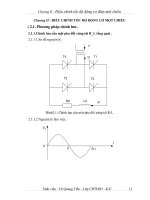
2AZ-FE Engine A
2GR-FE Engine A
Output
(HP) (kW)
140
180
Torque
(N.m) (ft.lbf)
180
240
220
160
200
180
140
160
140
160
140
120
100
120
120
100
100
80
60
Output
(HP) (kW)
280
200
260
Torque
(N.m) (ft.lbf)
260
340
320
300
80
280
60
260
240
240
180
220
160
240
200
220
180
200
160
120
140
100
180
120
100
40
40
20
80
60
60
40
20
0
1000 2000 3000 4000 5000 6000 7000
Engine Speed (rpm)
80
40
20
0
140
0
20
0
1000 2000 3000 4000 5000 6000 7000
01MMO39Y
Engine Speed (rpm)
01MMO40Y
MO-30
NEW MODEL OUTLINE
Transaxle
D The U140F and U241E 4-speed automatic transaxles have been carried over from the ’05 model.
D New U151E and U151F 5-speed automatic transaxles are used.
D A new GF1A transfer is used.
4-speed Automatic
Transaxle Type
Transfer Type
U140F
U241E
U151F
U151E
GF1A
—
GF1A
—
Combination with Engine
Gear
Ratio*
5-speed Automatic
2AZ-FE
2GR-FE
Drive Type
4WD
2WD
4WD
2WD
1st
3.938
3.943
4.235
z
2nd
2.194
2.197
2.360
z
3rd
1.411
1.413
1.517
z
4th
1.019
1.020
1.047
z
5th
—
—
0.756
z
3.141
3.145
3.378
z
Reverse
*: Counter Gear Ratio Included
Active Torque Control 4WD System
D A new active torque control 4WD system with an electric control coupling is used.
D The active torque control 4WD system, which has an electric control coupling in the front part of the rear
differential, transmits torque to the rear wheels when needed, and only in the amount needed, based on
information provided by various sensors.
D By operating the four-wheel drive lock switch provided on the instrument panel, the driver can select the
following modes: the AUTO mode to optimally control the torque that is transmitted to the rear wheels,
and the LOCK mode that locks the torque that is transmitted to the rear wheels to the maximum amount.
Electric Control
Coupling
Transfer Propeller
Shaft
Rear
Differential
Engine
Front
Differential
Transaxle
Control
Current
4WD
ECU
Speed Sensor
01NMO86Y
Four-wheel Drive Lock Switch
Yaw Rate & Deceleration Sensor
Steering Angle Sensor
ECM
System Configuration Diagram
01NMO87Y
MO-31
NEW MODEL OUTLINE
Chassis
Front Suspension
Type
Rear Suspension
MacPherson Strut Type
Independent Suspension
Type
Double Wishbone Type
Independent Suspension
01MCH100Y
Steering
Type
Gear Type
EPS (Electronic Power Steering)
Rack & Pinion
Brake
Front Brake Type
Ventilated Disc
Front Rotor Size
15 inch: 275 x 25 mm (10.82 x 0.87 in.)*1
16 inch: 296 x 28 mm (11.84 x 1.10 in.)*2
Rear Brake Type
Solid Disc
Rear Rotor Size
15 inch: 281 x 12 mm (11.24 x 0.48 in.)
Parking Brake
Type
Lever Type
Brake Control
ABS (Anti-lock Brake System) with EBD (Electronic Brake force Distribution) &
Brake Assist & TRAC (Traction Control) & Hill-start Assist Control*3 & DAC
(Downhill Assist Control)*3 & VSC (Vehicle Stability Control)*4
*1: 2AZ-FE Engine Models with Rear No. 1 Seat Only
*2: 2GR-FE Engine Models and Models with Rear No. 2 Seat
*3: Standard Equipment on 2GR-FE Engine Models and Models with Rear No. 2 Seat
*4: 2WD models have been provided with Auto LSD (Limited Slip Differential).
MO-32
NEW MODEL OUTLINE
Enhanced VSC System
D The enhanced VSC (Vehicle Stability Control) system is standard equipment on all models.
D In addition to the ABS, TRAC, and VSC controls provided by the conventional system, the enhanced
VSC system effects cooperative control with the EPS (Electric Power Steering) and active torque control
4WD system in order to realize excellent driving stability and maneuverability.
D See CH-92 for details on the enhanced VSC system.
Hill-start Assist Control
D The hill-start assist control is standard equipment on the 2GR-FE engine models and the models with rear
No. 2 seat.
D When the driver transfers his/her foot from the brake pedal to the accelerator pedal while starting off on
an uphill, the hill-start assist control momentarily maintains the hydraulic pressure in the wheel cylinders
of the four wheels, in order to prevent the vehicle from rolling backward.
D The hill-start assist control used on the ’06 model effects control to prevent the vehicle from rolling
backward. This control has evolved further from the hill-start assist control of the ’05 model, which
slowed the backward rolling of the vehicle while starting off on a hill.
D See CH-120 for details on the hill-start assist control.
Standstill
Slow Backward Movement
01NMO88Y
’06 Model
01NMO89Y
’05 Model
EG-2
ENGINE - 2AZ-FE ENGINE
ENGINE
2AZ-FE ENGINE
JDESCRIPTION
The 2AZ-FE engine is an in-line, 4-cylinder, 2.4-liter, 16-valve DOHC engine. This engine uses the VVT-i
(Variable Valve Timing-intelligent) system, DIS (Direct Ignition System), ETCS-i (Electronic Throttle
Control System-intelligent). It has been developed to realize high performance, quietness, fuel economy and
clean emission.
01NEG49Y
01NEG50Y
EG-3
ENGINE - 2AZ-FE ENGINE
"
Engine Specifications A
No. of Cyls. & Arrangement
4-cylinder, In-line
Valve Mechanism
16-valve DOHC, Chain Drive (with VVT-i)
Combustion Chamber
Pentroof Type
Manifolds
Cross-flow
Fuel System
SFI
Ignition System
DIS
Displacement
cm3 (cu. in.)
Bore x Stroke
mm (in.)
2362 (144.1)
88.5 x 96.0 (3.48 x 3.78)
Compression Ratio
9.8 : 1
Max. Output*1
(SAE-NET)
124 kW @ 6000 rpm (166 HP @ 6000 rpm)
Max. Torque*1
(SAE-NET)
224 N.m @ 4000 rpm (165 ft-lbf @ 4000 rpm)
Intake
Valve Timing
Exhaust
Open
3_ - 43_ BTDC
Close
65_ - 25_ ABDC
Open
45_ BBDC
Close
3_ ATDC
Firing Order
1-3-4-2
Research Octane Number
91 or higher
Octane Rating
87 or higher
Oil Grade
ILSAC
Tailpipe Emission Regulation
ULEV-II, SFTP
Evaporative Emission Regulation
LEV-II, ORVR
Engine Service Mass*2 (Reference)
kg (lb)
138 (304.2)
*1: Maximum output and torque rating is determined by revised SAE J1349 standard.
*2: Weight shows the figure with oil and water fully filled.
"
Valve Timing A
: Intake Valve Opening Angle
: Exhaust Valve Opening Angle
TDC
VVT-i Operation
Range
3_
3_
43_
65_
45_
VVT-i Operation
Range
25_
BDC
01MEG02Y
EG-4
ENGINE - 2AZ-FE ENGINE
JFEATURES OF 2AZ-FE ENGINE
The 2AZ-FE engine has achieved the following performance through the use of the items listed below.
(1) High performance and reliability
(2) Low noise and vibration
(3) Lightweight and compact design
(4) Good serviceability
(5) Clean emission and fuel economy
Section
Engine
Proper
p
Valve
V
l
Mechanism
Item
(1)
(2)
A cylinder block made of aluminum alloy along with a
magnesium alloy die-cast cylinder head cover is used.
A taper squish shape is used for the combustion chamber.
(3)
(4)
f
f
f
A resin gear balance shaft is used.
f
f
A timing chain and chain tensioner are used.
f
f
The shim-less type valve lifters are used.
f
The VVT-i system is used.
f
f
f
f
f
A chacoal filter is used in the air cleaner cap.
Intake and
Exhaust
S
System
Fuel
System
Intake manifold made of plastic is used.
f
The linkless-type throttle body is used.
f
f
A thin-wall ceramic TWC (Three-Way Catalytic converter)
is used.
f
The fuel returnless system is used.
f
f
f
Quick connectors are used to connect the fuel hose with the
fuel pipe.
f
f
f
12-hole type fuel injectors with high atomizing performance
are used.
f
Ignition
System
Iridium-tipped spark plugs are used.
f
Charging
System
The segment conductor type generator is used.
f
Starting
System
PS (Planetary reduction-Segment conductor motor) type
starter is used.
f
The ETCS-i is used.
f
The DIS (Direct Ignition System) makes ignition timing
adjustment unnecessary.
f
The non-contact type sensor is used in the throttle position
sensor.
f
Engine
Control
System
(5)
The planar type air-fuel ratio sensor is used.
f
f
f
f
f
f
f
f
f
EG-5
ENGINE - 2AZ-FE ENGINE
JENGINE PROPER
1. Cylinder Head Cover
D A lightweight magnesium alloy die-cast
cylinder head cover is used.
Cylinder Head Cover
D Acrylic rubber, which excels in heat resistance
and reliability, is used for the cylinder head
cover gasket.
Cylinder Head Cover Gasket
DR011EG20
2. Cylinder Head Gasket
A steel-laminate type cylinder head gasket is used. A shim has been added around the cylinder bore to
increase the sealing surface, thus improving the sealing performance and durability.
Cylinder
Bore Side
Outer
Side
A
A
Shim
Front
02AEG01Y
A - A Cross Section
02AEG02Y
EG-6
ENGINE - 2AZ-FE ENGINE
3. Cylinder Head
D Through the adoption of the taper squish combustion chamber, the engine knocking resistance and fuel
efficiency have been improved.
D An upright intake port is used to improve the intake efficiency.
D Installing the injectors in the cylinder head enables the injectors inject fuel as close as possible to the
combustion chamber. This prevents the fuel from adhering to the intake port walls, which reduces HC
exhaust emissions.
D The routing of the water jacket in the cylinder head has been optimized to realize the high cooling
performance. In addition, a water bypass passage has been provided below the exhaust ports to reduce the
number of parts and the weight.
Injector
Exhaust Side
A
IN
EX
Bypass
Passage
A
Intake Side
Taper Squish
DR011EG21
208EG67
A - A Cross Section
EG-7
ENGINE - 2AZ-FE ENGINE
4. Cylinder Block
D Lightweight aluminum alloy is used for the cylinder block.
D By producing the thin cast-iron liners and cylinder block as a unit, compaction is realized.
D Air passage holes are provided in the crankshaft bearing area of the cylinder block. As a result, the air at
the bottom of the cylinder flows smoother, and pumping loss (back pressure at the bottom of the piston
generated by the piston’s reciprocal movement) is reduced to improve the engine’s output.
D The oil filter and the air conditioning compressor brackets are integrated into the crankcase. Also, the
water pump swirl chamber and thermostat housing are integrated into the cylinder block.
"
Air Flow During Engine Revolution A
Water Pump
Swirl Chamber
Air Passage Holes
Crankshaft
Bearing Cap
Thermostat Housing
Plastic Region
Tightening Bolts
Air Conditioning
Compressor Brackets
01NEG26Y
NOTICE
Never attempt to machine the cylinder because it has a thin liner thickness.
Air Flow
DR011EG22
EG-8
ENGINE - 2AZ-FE ENGINE
D The liners are the spiny-type, which have been manufactured so that their casting exteriors form large
irregular surfaces in order to enhance the adhesion between the liners and the aluminum cylinder block.
The enhanced adhesion helps heat dissipation, resulting in a lower overall temperature and heat
deformation of the cylinder bores.
Irregularly shaped
outer casting
surface of liner
A
Cylinder Block
A
Liner
A - A Cross Section
01NEG27Y
D Water jacket spacers are provided in the water jacket of the cylinder block.
D They suppress the water flow in the center of the water jackets, guide the coolant above and below the
cylinder bores, and ensure uniform temperature distribution. As a result, the viscosity of the engine oil that
acts as a lubricant between the bore walls and the pistons can be lowered, thus reducing friction.
Water Jacket
A
A
Water Jacket
Spacer
A - A Cross Section
01NEG28Y
EG-9
ENGINE - 2AZ-FE ENGINE
5. Piston
D The piston is made of aluminum alloy and skirt area is made compact and lightweight.
D The piston head portion uses a taper squish shape to improve the fuel combustion efficiency.
D The piston skirt has been coated with resin to reduce the friction loss.
: Resin Coating
Taper Squish Shape
01MEG01Y
6. Connecting Rod
D The connecting rods and caps are made of
high-strength steel for weight reduction.
D Nut-less type plastic region tightening bolts are
used on the connecting rod for a lighter design.
D The connecting rod bearings are reduced in
width to reduce friction.
240EG45
Plastic Region Tightening Bolts
EG-10
ENGINE - 2AZ-FE ENGINE
7. Crankshaft
D The forged crankshaft has 5 journals and 8 balance weights.
D The crankshaft is made of forged steel.
D Pin and journal fillets are roll-finished to maintain adequate strength.
D The balance shaft drive gear is provided for the crankshaft.
Balance Shaft Drive Gear
No.1 Journal
Oil Hole
Balance Weight
Crank Pin
01NEG31Y
8. Balance Shaft
General
D A balance shaft is used to reduce vibrations.
D The crankshaft directly drives the No. 1 balance shaft.
D In addition, a resin gear is used on the driven side to suppress noise and offer lightweight design.
Crankshaft
Balance Shaft Drive Gear
: Resin Gear
Balance Shaft No.2
Balance Shaft No.1
Balance Shaft
Housing
01NEG32Y
EG-11
ENGINE - 2AZ-FE ENGINE
Operation
Top Dead Center
In the in-line 4-cylinder engine, the crankshaft
angle for cylinders No.1 and No.4 are exactly at
the opposite (180_) position of cylinders No.2
and No.3. Therefore, the inertial force of the
pistons and the connecting rods of the former 2
cylinders and of the latter 2 cylinders almost
cancel each other. However, because the position
at which the piston reaches its maximum speed
is located toward the top dead center from the
center of the stroke, the upward inertial force is
greater than the downward inertial force. This
unbalanced secondary inertial force is generated
twice for each rotation of the crankshaft.
Point of Max. Speed
90_
Point of
Max. Speed
- 90_
Combined Inertial Force of
All Cylinders
Unbalanced Secondary
Inertial Force
Inertial force that cannot be canceled
90_
270_
Crankshaft Angle
0_
- 180_
Point of
Max. Speed
286EG71
Force
Inertial Force of Cylinders
No.2 and No.3
Bottom Dead Center
180_
Inertial Force of Cylinder
No.1 and No.4
Inertial Force Generated by the In-line 4 Cylinders
286EG72
To cancel the unbalanced secondary inertial force, 2 balance shafts are rotated twice for each rotation of
the crankshaft and generate inertial force in the opposite direction. Also, in order to cancel the inertial force
generated by the balance shaft itself, the balance shaft actually consists of 2 shafts rotating in opposite
directions.
Inertial Force of Balancer
0_
A
B
90_
180_
C
E
D
270_
Crankshaft Angle
Secondary Inertial Force
Mass Direction of
Balance Shaft
Inertial Force of
Balancer
Mass Direction of Balance Shaft at Crankshaft Angle
286EG73
EG-12
ENGINE - 2AZ-FE ENGINE
JVALVE MECHANISM
1. General
D The VVT-i system is used to improve fuel economy, engine performance and reduce exhaust emissions.
For details of VVT-i system, see page EG-48.
D The intake and exhaust camshafts are driven by a timing chain.
D Along with the increase in the amount of valve lift, the shim-less type valve lifter is used. This valve lifter
increases the cam contact surface.
Intake Camshaft
VVT-i Controller
Exhaust
Camshaft
Camshaft
Valve
Lifter
Chain
Tensioner
Chain Damper
Chain Slipper
181EG10
240EG46
Service Tip
The adjustment of the valve clearance is accomplished by selecting and replacing the appropriate
valve lifters.
A total of 35 valve lifters are available in 0.02 mm (0.008 in.) increments, from 5.06 mm (0.199 in.)
to 5.74 mm (0.226 in.). For details, refer to 2006 RAV4 Repair Manual (Pub. No. RM01M1U).
EG-13
ENGINE - 2AZ-FE ENGINE
2. Camshaft
D The intake camshaft is provided with timing rotor to trigger the camshaft position sensor.
D In conjunction with the adoption of the VVT-i system, an oil passage is provided in the intake camshaft
in order to supply engine oil pressure to the VVT-i system.
D A VVT-i controller has been installed on the front of the intake camshaft to vary the timing of the intake
valves.
Timing Rotor
Intake Camshaft
VVT-i Controller
Exhaust Camshaft
Timing Sprocket
181EG11
3. Timing Chain
D A roller chain with an 8 mm (0.315 in.) pitch is used to make the engine more compact.
D The timing chain is lubricated by an oil jet.
D The chain tensioner uses a spring and oil pressure to maintain proper chain tension at all times.
D The chain tensioner suppresses noise generated by the timing chain.
D A ratchet type non-return mechanism is used.
D To achieve excellent serviceability, the chain tensioner is constructed so that it can be removed and
installed from the outside of the timing chain cover.
Chain
Tensioner
Cam Spring
Chain Damper
Cam
Chain Slipper
Spring
Plunger
Oil Jet
181EG14
Chain Tensioner
185EG25
EG-14
ENGINE - 2AZ-FE ENGINE
JLUBRICATION SYSTEM
1. General
D The lubrication circuit is fully pressurized and oil passes through an oil filter.
D The trochoid gear type oil pump is chain-driven by the crankshaft.
D The oil filter is attached downward from the crankcase to improve serviceability.
D Along with the adoption of the VVT-i system, the cylinder head is provided with a VVT-i controller and
a camshaft timing oil control valve. This system is operated by the engine oil.
VVT-i Controller
Camshaft Timing
Oil Control Valve
Chain
Tensioner
Oil Return
Hole
Oil Filter
Oil Pump
208EG07
"
Oil Circuit A
Main Oil Hole
Bypass
Valve
Oil Filter
Exhaust
Camshaft
Journal
Chain
Tensioner
Relief
Valve
Crankshaft
Journal
Cylinder Head
Oil Pump
Oil Control
Valve
Intake
Camshaft
Journal
Oil Strainer
Crankshaft
Pin
Cylinder
Block
Barance
Shaft
Oil Jet
Timing
Chain
Piston
VVT-i Controller
Oil Pan
01NEG33Y
EG-15
ENGINE - 2AZ-FE ENGINE
"
Oil Capacity A
Liters (US qts, Imp. qts)
Dry
5.0 (5.3, 4.4)
with Oil Filter
4.3 (4.5, 3.8)
without Oil Filter
4.1 (3.8, 3.1)
2. Oil Jet
D Piston oil jets for cooling and lubricating the pistons are used in the cylinder block.
D These oil jets contain a check valve to prevent oil from being fed when the oil pressure is low. This prevents
the overall oil pressure in the engine from dropping.
Oil Jets
Check
Valve
Bottom Side View
Oil
Oil Jet Cross Section
01NEG34Y
EG-16
ENGINE - 2AZ-FE ENGINE
JCOOLING SYSTEM
D The cooling system uses a pressurized forced-circulation system with pressurized reservoir tank.
D A thermostat with a bypass valve is located on the water inlet housing to maintain suitable temperature
distribution in the cooling system.
D An aluminum radiator core is used for weight reduction.
D The flow of the engine coolant makes a U-turn in the cylinder block to ensure a smooth flow of the engine
coolant. In addition, a bypass passage is enclosed in the cylinder head and the cylinder block.
D Warm water from the engine is sent to the throttle body to prevent freeze-up.
D The TOYOTA genuine Super Long Life Coolant (SLLC) is used.
Throttle Body
To Heater Core
To Radiator
Bypass Passage
Thermostat
Water Pump
From Radiator
01NEG35Y
"
System Diagram A
Cylinder Head
Heater Core
Bypass Passage
Water Pump
Cylinder Block
Thermostat
Reservoir
Tank
Throttle
Body
Radiator
01NEG59Y
EG-17
ENGINE - 2AZ-FE ENGINE
"
Engine Coolant Specifications A
Type
TOYOTA genuine Super Long Life Coolant
(SLLC) or similar high quality ethylene
glycol based non-silicate, non-amine,
non-nitrite and non-borate coolant with
long-life hybrid organic acid technology
(coolant with long-life hybrid organic acid
technology is a combination of low
phosphates and organic acids.) Do not use
plain water alone.
Color
Pink
Engine
Coolant
Capacity
Liters (US qts, Imp. qts)
Maintenance
Intervals
Thermostat
Opening Temperature
M/T
6.6 (7.0, 5.8)
A/T
6.7 (7.1, 5.9)
First Time
100,000 mile (160,000 km)
Subsequent
Every 50,000 mile (80,000 km)
_C (_F)
80 - 84 (176 - 183)
D SLLC is pre-mixed (the U.S.A. models: 50 % coolant and 50 % deionized water, the Canada. models:
55 % coolant and 45 % deionized water). Therefore, no dilution is needed when SLLC in the vehicle is
added or replaced.
D If LLC is mixed with SLLC, the interval for LLC (every 25,000 miles / 40,000 km or 24 months
whichever comes first) should be used.
D You can also apply the new maintenance interval (every 50,000 miles / 80,000 km) to vehicles initially
filled with LLC (red-colored), if you use SLLC (pink-colored) for the engine coolant change.
EG-18
ENGINE - 2AZ-FE ENGINE
JINTAKE AND EXHAUST SYSTEM
1. General
D The linkless-type throttle body is used to realize excellent throttle control.
D ETCS-i (Electronic Throttle Control System-intelligent) is used to provide excellent throttle control. For
details, see page EG-43.
D A plastic intake manifold is used for weight reduction.
D A stainless steel exhaust manifold is used for weight reduction.
Main Muffler
Intake Manifold
Exhaust Manifold
Sub Muffler
TWC
TWC
Air Cleaner
01MEG32Y
EG-19
ENGINE - 2AZ-FE ENGINE
2. Air Cleaner
D A nonwoven, full-fabric type air cleaner element is used.
D A charcoal filter, which adsorbs the HC that accumulates in the intake system when the engine is stopped,
is used in the air cleaner cap in order to reduce evaporative emissions.
Air Cleaner Cap
Charcoal Filter
Air Cleaner Element
(Nonwoven Fabric)
01MEG10Y
Service Tip
The charcoal filter, which is maintenance-free, cannot be removed from the air cleaner cap.
3. Throttle Body
D The linkless-type throttle body is used and it realizes excellent throttle control.
D A DC motor with excellent response and minimal power consumption is used for the throttle control motor.
The ECM performs the duty ratio control of the direction and the amperage of the current that flows to
the throttle control motor in order to regulate the opening angle of the throttle valve.
Throttle Position
Sensor
Throttle Control Motor
01NEG42Y
EG-20
ENGINE - 2AZ-FE ENGINE
4. Intake Manifold
D The intake manifold has been made of plastic to reduce the weight and the amount of heat transferred from
the cylinder head. As a result, it has become possible to reduce the intake air temperature and improve the
intake volumetric efficiency.
D A mesh type gasket is used, in order to reduce the intake noise.
Mesh Type Gasket
01NEG37Y
5. Exhaust Manifold
A stainless steel exhaust manifold is used for improving the warm-up of TWC (Three-Way Catalytic
converter) and for weight reduction.
TWC
01NEG38Y
EG-21
ENGINE - 2AZ-FE ENGINE
6. Exhaust Pipe
D The exhaust pipe uses two ball joints in order to achieve a simple construction and ensured reliability.
D The TWC can improve exhaust emission by optimizing the cell density and the wall thickness.
Ball Joint
Sub Muffler
Spring
Gasket
Bolt
Ball Joint
Main Muffler
Ball Joint
TWC
01MEG33Y
EG-22
ENGINE - 2AZ-FE ENGINE
JFUEL SYSTEM
1. General
D The fuel returnless system is used to reduce evaporative emissions.
D A fuel cut control is used to stop the fuel pump when the SRS airbag is deployed in a front or side collision.
For details, see page EG-53.
D A quick connector is used in the fuel main pipe to improve serviceability.
D The 12-hole type fuel injector is used.
D The ORVR (On-board Refueling Vapor Recovery) system is used. For details, see page EG-54.
Fuel Pump Assembly
D Fuel Filter
D Pressure Regulator
Quick Connector
Injector
Fuel Tank
Canister
01MEG30Y