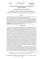
Effect of filling ratio on heat trasfer performance in multi-heat pipe with graphene oxide nanofluid
Bạn đang xem bản rút gọn của tài liệu. Xem và tải ngay bản đầy đủ của tài liệu tại đây (1.04 MB, 6 trang )
<span class='text_page_counter'>(1)</span><div class='page_container' data-page=1>
<b>EFFECT OF FILLING RATIO ON HEAT TRASFER</b>
<b>PERFORMANCE IN MULTI-HEAT PIPE </b>
<b>WITH GRAPHENE OXIDE NANOFLUID</b>
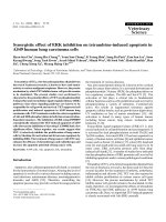
<i><b>Shuichi Torii</b><b>1</b><b><sub>*</sub></b></i>
<i><b>Abstract: This experimental study is performed to investigate heat transfer performance of a multi-heat </b></i>
<i>pipe cooling device in the condition of different filling ratio (40%, 60%, 80% and 100%) under constant </i>
<i>heat flux conditions. Here, pure water and graphene oxide (GO) nanofluid are employed as working fluid. </i>
<i>Temperature fields and thermal resistance are measured for different filling ratio, heat fluxes and volume </i>
<i>concentrations. It was found that (i) the thermal performance of heat pipe increases with increasing the </i>
<i>concentration of GO nanoparticles in the base fluid, while the maximum heat transfer enhancement yields at </i>
<i>0.2% volume concentration, (ii) GO/water nanofluid shows lower thermal resistance compared to pure water, </i>
<i>(iii) the optimal thermal resistance is obtained at 100% filling charge ratio with 0.2% volume concentration, </i>
<i>and (iv) heat transfer coefficient of the heat pipe significantly increases with an increase in heat flux and GO </i>
<i>nanoparticles concentration.</i>
<i><b>Keywords: Multi-heat pipe; graphene oxide; gilling ratio; volume fraction; thermal resistance.</b></i>
<i>Nhận ngày 10/5/2017; sửa xong 12/6/2017; chấp nhận đăng 23/6/2017 </i>
<i>Received: May 10, 2017; revised: June 12, 2017; accepted: June 23, 2017</i>
<i>1<sub>Prof.Dr, Department of Mechanical System Engineering, Graduate School of Science and Technology.</sub></i>
<i>*Corresponding author. E-mail: </i>
<b>1. Introduction</b>
A multi-heat pipe is a device that transfers heat from the hot interface to the cold one by phase
change and convection of the working fluid. Vapor is generated at the heat source level (evaporator) and
it condenses at the heat sink level (condenser). The liquid returns from the evaporator to the condenser
through a capillary structure. Heat pipes have a variety of advantages, such as high heat removal rate
per unit volume, a fully passive working principle, and easy applicability. Heat pipes have been used in
various thermal engineering fields such as computer CPUs, solar energy collectors and micro device
transmitting equipment.
</div>
<span class='text_page_counter'>(2)</span><div class='page_container' data-page=2>
showed less thermal resistance and optimum heat transfer was obtained at nearly 30% filling ratio. For
ethanol at low heat input, the best performance was obtained at high filling ratio beyond 50% in the basis of
heat transfer. For high heat input, ethanol showed high heat transfer rate at high heat input for all filling ratio.
Pote A. and Pachghere [6] performed an experiment using ZnO/water nanofluid of 100 nm to investigate the
effect of concentration of zinc oxide nanoparticles on thermal resistance of a closed loop pulsating heat pipe
(CLPHP). Experiment was conducted in vertical orientation with 50% filling ratio. They found that thermal
resistance of CLPHP using ZnO/water nanofluid as working fluid was better than thermal resistance when
pure water is used. Verma et al. [7] studied experimentally the effect of filling charge ratio, inclination angle
and heat flux on the start-up and thermal performance in terms of thermal resistance and heat transfer
coef-ficient of a pulsating heat pipe using methanol and de-ionized (DI) water. They concluded that the minimum
start-up power and thermal resistance were obtained at 50% and 40% filling ratio for DI water and methanol,
respectively. Qu et al. [8] investigated experimentally the performance of a stainless steel oscillating heat
pipe (OHP) charged with base water and spherical Al2O3 particles of 56 nm in diameter. The effects of filling
ratios, mass fractions of alumina particles and power inputs on the total thermal resistance of the OHP were
investigated. They showed that the maximum thermal resistance was decreased by 0.14 o<sub>C/W (or 32.5%) </sub>
when the power input was 85.8W at 70% filling ratio and 0.9% mass fraction. Lin et al. [9] studied the effect
of silver nanofluid (20 nm in diameter) on copper pulsating heat pipe thermal performance. The thermal
per-formance was studied at different concentration (100ppm and 450 ppm), various filled ratio (20%~80% FR)
and different heat power (5W~85W). The results showed that the best filled ratio was 60% and the better
working fluid was 100 ppm of silver nanofluid. Khandekar et al [10] investigated the effect of working fluid
(water, ethanol and R-123) and filling ratio on the thermal performance of closed loop pulsating heat pipe in
vertical and horizontal orientation. They found that the best performance was measured at low filling ratio
for all working fluids. Salem et al. [11] measured thermal conductivity of graphene oxide/water nanofluid with
different volume concentration ranged from 0.05% to 0.2% using transient hot wire method (KD2 thermal
property meter). They showed that the thermal conductivity was enhanced with reference to pure water.
Also, it was increased by increasing nanoparticles concentration.
In the present work, experimental studies have been conducted on the thermal performance of a
cop-per multi-heat pipe charged with pure water and graphene oxide (GO)/water nanofluids as working fluid. The
experiment was performed at different volume concentration (0.05%, 0.1%, 0.15% and 0.2% vol.), various
filling charge ratio (40%, 60%, 80% and 100% FR) and different heat flux (10W~30W).
<b>2. Materials and Methods </b>
Graphene oxide nanofluid is prepared by dispersing GO nanoparticles into pure water as a base fluid.
GO nanoparticles were synthesized from natural graphite powder by a modified Hummers method [11,12].
Graphite fine powders (45 μm) was purchased from Wako pure chemical industries (Japan), concentrated
sulfuric acids (H2SO4), sodium nitrate (NaNO3), potassium permanganate (KMnO4), hydrogen peroxide (30%
H<sub>2</sub>O<sub>2</sub>), hydrochloric acid (5% HCL) and deionized water were used throughout Hummers method. GO/water
nanofluids with four different volume concentrations at 0.05%, 0.1%, 0.15% and 0.2% were prepared for
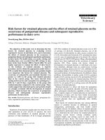
this experiment. Figure 1 represents a multi-heat pipe which consists of evaporator, adiabatic section and
condenser. A multi-heat pipe was made of copper in laboratory of Kumamoto university-Japan. The external
dimensions for heating and cooling sections are 45 × 45 × 8mm, and the internal dimensions are 42 × 42 ×
5mm. The adiabatic section is consisted of four parallel circular tubes whose dimension is ϕ6 (external
diam-eter) × ϕ5 (inlet diamdiam-eter) × 45 mm (length). As shown in figure, twelve k-type thermocouples were installed
on the test section, with five of them embedded in the evaporator section (H1, H2, H3, H4, and H5), four in
the adiabatic section (a1, a2, a3, and a4), and three in the condenser (C1, C2 and C3).
</div>
<span class='text_page_counter'>(3)</span><div class='page_container' data-page=3>
vacuum pump to remove the non-condensable gases. Cooling water was then supplied from thermostatic
bath to the cooling chamber at a volume flow rate of 1.5 l/min and 15o<sub>C. The test section was then charged </sub>
with the working fluid. The filling charge ratios (FR) (volume ratio of the working fluid to the internal volume
of the evaporator section) were varied at 40%, 60%, 80% and 100% for each working fluid. The vacuum
pressure inside the test section was set to 9.5 kPa for all cases. The test section was heated gradually until
a steady state was attained.
<i><b>Figure 1. Multi-heat pipe with thermocouple locations (all dimensions are in mm)</b></i>
<i><b>Figure 2. Schematic of experimental set-up</b></i>
<b>3. Results and discussion</b>
</div>
<span class='text_page_counter'>(4)</span><div class='page_container' data-page=4>
The evaporator and condenser wall temperature, therefore, are calculated as the arithmetic average
of the thermocouples located in the evaporator and condenser sections. The mean temperature of
evapora-tor and condenser sections are calculated and plotted against the heat load at different volume
concentra-tions and filling ratios in Figure 3.
The results indicate that an increase of heat flux leads to increase the evaporator and condenser
wall temperature at different volume concentration and filling ratio. This is due to high heat flux causes an
increase of the evaporation of working fluid leading to increase pressure in the heat pipe affecting higher
sat-uration temperature of working fluid in heat pipe. The wall temperature of the heat pipe reduces from
evap-orator to condenser section. Also, a rough comparison between pure water and GO/water nanofluids shows
that presence of GO nanoparticles significantly reduces the evaporator temperature and slightly increases
the condenser temperature, which means that the thermal performance of the heat pipe greatly enhances,
when GO nanoparticles are added into pure water.
<i><b>Figure 3. Wall temperatures as a function of input heat load and filling ratio</b></i>
Based on the experimental results, the mean wall temperature of evaporator reduced as the filling
charge ratio increased for volume concentration 0.15% and 0.2% at the same input heat flux. For pure
wa-ter, 0.05% and 0.1% volume concentration, evaporator temperature decreases with the rise of filling ratio
till 80%, but it decreased when the filling ratio reached 100% for 0.1% vol. at different heat load and after
15W for pure water and 0.05%volume concentration. The condenser temperature increases in slow rate with
increment of filling ratio. The highest condenser temperature is obtained at 100% filling ratio for pure water,
0.05%, 0.15% and 0.2% vol. and at 80% for 0.1% volume concentration.
</div>
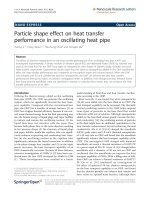
<span class='text_page_counter'>(5)</span><div class='page_container' data-page=5>
reduced by 17.82%, 18.76%, 25.24% and 22.10% for 100%, 80%, 60% and 40% filling ratio, respectively).
The overall heat transfer coefficient of the heat pipe calculated using the surface temperature of evaporator
and condenser section using Equation (1).
(1)
<i>where: Ae</i> is the cross section area of the evaporator section.
Figure 4 shows the overall heat transfer coefficient against the heat load for all the filling charge ratios
and the volume concentrations. For GO/water nanofluid, a higher heat transfer coefficient is registered for
all volumetric concentrations of nanoparticles in comparison with those reported for pure water at a similar
condition. The GO nanoparticles in the heat pipe not only increased the fluid thermal conductivity but also
enhanced the heat transfer coefficient due to the particles migration. It is clear from Figure 4 that the
in-crease of the heat load intensifies the heat transfer coefficient of the heat pipe for each filling ratio.
<i><b>Figure 4. Overall heat transfer coefficient as a function of input heat load and filling ratio</b></i>
Results demonstrate that the heat transfer coefficient of heat pipe drastically increases with
increas-ing the fillincreas-ing charge ratio at the same input heat fluxes, because the temperature difference between the
evaporator and condenser section decreases with increasing the filling charge ratio. The optimum heat
transfer coefficient was obtained at 100% filling ratio for 0.15 vol.% and 0.2 vol.% and at 80% for 0.1%
volume concentration. For pure water and 0.05 vol.%, the heat transfer coefficient increases with the rise
of filling ratio till 15W input heat load. Beyond 15W, the maximum heat transfer coefficient was obtained at
80% filling ratio.
<b>4. Conclusion</b>
</div>
<span class='text_page_counter'>(6)</span><div class='page_container' data-page=6>
(40%, 60%, 80% and 100%) and different volume concentrations of graphene oxide/water nanofluids
(0.05%, 0.1%, 0.15% and 0.2%) in vertical orientation. The main outcomes are resumed below:
- The heat transfer performance of a multi-heat pipe is apparently improved after the addition of GO
nanoparticles in the working fluid.
- 0.2% is the optimal volume concentration of GO/water nanofluids to achieve the maximal heat
trans-fer enhancement for the filling ratios 40%, 60%, 80% and 100%.
- Compared with the pure water, the maximal decrease of evaporator temperature is 17.82%, 18.76%,
25.24% and 22.10% for 100%, 80%, 60% and 40% filling ratio at 0.2% volume concentration.
- With increasing the input heat power and volumetric concentration of nanofluid, the overall thermal
resistance of the heat pipe is increased.
- The optimal thermal resistance of a multi-heat pipe is obtained at 100% filling charge ratio for 0.2%
volume concentration.
- For all working fluids and filling ratios, the overall heat transfer coefficient of this multi-heat pipe
increases by increasing the input heat power.
- For all filling ratios, the overall heat transfer coefficient improves with increasing the volumetric
concentration of GO/water nanofluids.
- The overall heat transfer coefficient depends greatly on the filling ratio, and the lower filling ratio
(40%) yields smaller heat transfer coefficient.
<b>References</b>
1. Kim K., Bang I. (2016), “Comparison of flooding limit and thermal performance of annular and concentric
<i>thermosyphons at different fill ratios”, Applied Thermal Engineering, 99:179-188. </i>
2. Sarafraz M., Hormozi F. (2014), “Experimental study on the thermal performance and efficiency of a
<i>copper made thermosyphon heat pipe charged with alumina–glycol based nanofluids”, Powder Technology, </i>
266:378-387.
3. Lips S., Lefèvre F., Bonjour J.(2010), “Combined effects of the filling ratio and the vapour space thickness
<i>on the performance of a flat plate heat pipe”, International Journal of Heat and Mass Transfer, 53:694-702.</i>
4. Mameli M., Manno V., Filippeschi S., Marengo M.,(2014), “Thermal instability of a Closed Loop
<i>Pulsat-ing Heat Pipe: Combined effect of orientation and fillPulsat-ing ratio”, Experimental Thermal and Fluid Science, </i>
59:222-229.
5. Barua H., Ali M., Nuruzzaman M., Islam M., Feroz C. (2013), “Effect of filling ratio on heat transfer
<i>charac-teristics and performance of a closed loop pulsating heat pipe”, in proc. 5th BSME International Conference </i>
<i>on Thermal Engineering, 56:88-95.</i>
6. Pote A., Pachghere (2015), “Experimental Analysis on Thermal Performance of Closed Loop Pulsating Heat
<i>Pipe Using Zno/Water Nanofluid”, International Journal of Science and Research (IJSR), 4:235-239.</i>
7. Verma B., Yadav V., Srivastava K.(2013), “Experimental Studies on Thermal Performance of a Pulsating
<i>Heat Pipe with Methanol/DI Water”, Journal of Electronics Cooling and Thermal Control, 3:27-34.</i>
8. Qu J., Wu H. and Cheng P., (2010), “Thermal performance of an oscillating heat pipe with Al2O3–water
<i>nanofluids”, International Communications in Heat and Mass Transfer, 37:111-115.</i>
9. Lin Y., Kang S., Chen H. (2008), “Effect of silver nano-fluid on pulsating heat pipe thermal performance”,
<i>Applied Thermal Engineering, 28:1312-1317.</i>
10. Khandekar S., Dollinger N., Groll M.(2003), “Understanding operational regimes of closed loop pulsating
<i>heat pipes: an experimental study”, Applied Thermal Engineering, 23:707-719.</i>
11. Salem M., Bassily M., Meakhail T., Torii S.(2016), “Experimental Investigation on Heat Transfer and
<i>Pressure Drop Characteristics of Graphene Oxide/Water Nanofluid in a Circular Tube”, IPASJ International </i>
<i>Journal of Mechanical Engineering, 4:12-22.</i>
</div>
<!--links-->