A Method for Automated Test Cases Generation from Sequence Diagrams and Object Constraint Language for Concurrent Programs
Bạn đang xem bản rút gọn của tài liệu. Xem và tải ngay bản đầy đủ của tài liệu tại đây (951.63 KB, 18 trang )
<span class='text_page_counter'>(1)</span><div class='page_container' data-page=1>
A Method for Automated Test Cases Generation
from Sequence Diagrams and Object Constraint Language
for Concurrent Programs
Thi-Dao Vu
1,∗, Pham Ngoc Hung
2, Nguyen Viet Ha
21<sub>Academy of Cryptography of Techniques,</sub>
141 Chien Thang street, Tan Trieu, Thanh Tri, Hanoi, Vietnam
2<sub>Faculty of Information Technology, VNU University of Engineering and Technology,</sub>
E3 Building, 144 Xuan Thuy Street, Cau Giay, Hanoi, Vietnam
Abstract
This paper proposes an automated test cases generation method from sequence diagrams, class diagrams, and
object constraint language in order to solve several steps of the model-based testing process. The method supports
UML 2.0 sequence diagrams including eight kinds of combined fragments. Test cases are generated with respect
to the given concurrency coverage criteria. With strong concurrency coverage, generating exhaustive test cases for
all concurrent interleaving sequences is exponential in size. The key idea of this method is to create selections of
possible test scenarios in special case of exploring the message sequences with their possible interleaving in parallel
fragments or weak sequencing fragments. Test data for testing loop fragments are also generated. A tool supporting
the proposed method is implemented and tested with several case studies. The obtained results show the feasibility
and effectiveness of the method.
Received 10 June 2016, Revised 27 October 2016, Accepted 31 October 2016
Keywords: Model based Testing, Test Scenario, Test Data, Test Case, Sequence Diagram, Class Diagram, Object
Constraint Language.
1. Introduction
Model- based testing plays a significant
role in practice and a lot of researches on it
has been investigated in recent years due to
great benefits. There are some approaches
for model-based testing such as test data
generation, test cases generation from
behavior models, and test scripts generation
∗<sub>Corresponding author. Email.: </sub>
from abstract tests [1]. Generation of
executable test cases from Unified Modeling
Language (UML) sequence diagrams and
Object Constraint Language (OCL) is one
of major approaches. By this approach, it
is easier to obtain accurate behavior models
in order to apply in the software companies.
The translation of a sequence diagram into
an intermediate graph [2, 3] is mandatory for
generating all possible scenarios. These test
scenarios denote abstract test cases that will
</div>
<span class='text_page_counter'>(2)</span><div class='page_container' data-page=2>
help to find errors during implementation of
software systems.
There are many proposed works in order
to show that approach. Some methods
of test cases generation from models did
not address different types of combined
fragments and in case nested combined
fragments [4, 5]. An approach in [2]
dealt with five combined fragments such
as repetition (loop), selection (alt/opt/break),
and concurrencies (par) in UML 2.0 [6].
However, it only executed one iteration
in loop fragments. Therefore, the loops
need to be generated more test scenarios.
Moreover, this approach did not generate all
possible test scenarios (in special case of
parallel fragments). Some problems such as
deadlocks and synchronization in concurrent
systems are solved in [7, 3], but this method
did not handle test data generation.
When generating test cases from UML
sequence diagrams and OCL, we first
need to construct a set of test scenarios
which represents a sequence of performed
operations in a software system. One
challenging task is how to derive a
comprehensive test scenarios when the
system under testing is complex and the
number of test scenarios may be huge.
Therefore, there are the following difficulties
facing in the automatic test cases generation.
• Concurrency in a sequence diagram
is attributed by weak sequencing
(seq) or parallel (par) fragments.
Concurrent programs may behave
nondeterministically. It may result
in different outputs when repeated
with the same inputs in different runs.
Therefore, test cases generation in
concurrent programs have a degree
of nondeterminism that sequential
programs do not support.
• Coverage of concurrency and branch
features could lead to a huge number
of test scenarios. However, some
test scenarios could not be tested
because some infeasible test scenarios
correspond to unreachable paths.
• Generating test data for testing loop
fragments solves the problem that the
body of the loops is only executed once
in [2, 5].
This paper proposes a method in order
to deal with the above issues. The
method generates test scenarios from UML
2.0 sequence diagrams and OCL (in class
diagram) according to a given coverage
criterion for concurrent flows. The key idea
of this method is to select the possible test
scenarios in order to avoid the test scenarios
explosion. Next, test data are created from
the constraints by using one predicate at
a time and reducing domains of variables
step by step. For each test scenario, test
data generation procedure specially solves
the problems of testing loops. Therefore, test
scenarios help to detect errors in testing loops
and concurrency errors such as safety and
liveness property of the systems.
The rest of this paper is organized as
follows. Section 2 introduces some of the
basic concepts that used in this research.
A brief control-flow graph generation from
UML 2.0 sequence diagrams and class
diagrams is given in Sect. 3. Section 4
</div>
<span class='text_page_counter'>(3)</span><div class='page_container' data-page=3>
coverage criteria. Section 5 describes the
proposed test data generation. Section 6
presents a tool to implement the proposed
method and a case study to validate the
feasibility and effectiveness of the method.
Finally, we conclude the paper and discuss
future works in Sect. 7.
2. Background
In this section, we introduce some concepts
related to model- based testing, concurrency
coverage criterion, and mutation analysis.
2.1. Model–based testing
Model–based testing (MBT) automates
the detailed design of the test cases and
the generation of the traceability matrix
[1]. More precisely, instead of manually
writing hundreds of test cases (sequences
of operations), the test designer specifies
an abstract model of the system under test
(SUT), and then the MBT generates a set of
test cases from that model. By using MBT,
the test design time is reduced. Moreover,
an advantage of this approach can generate
a variety of test suites from the same
model simply by using different test selection
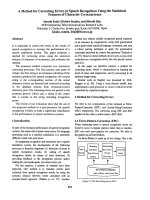
criteria. The MBT process can be divided
into the following five main steps shown
in Figure 1.
The first step of MBT is to specify an
abstract model of the SUT. The second step of
MBT is to generate set of abstract tests, which
are sequences of operations from the model.
The coverage reports some indications of
how well the generated test set exercises all
the behaviors of the model. The first two
steps distinguish MBT from other kinds of
testing. In online MBT tools, steps two
Fig. 1. The model-based testing process.
through four are usually merged into one step
whereas in offline MBT, they are separate.
The third step of MBT is to transform the
abstract tests into executable concrete tests.
This may be done by a transformation tool,
which uses various templates and mappings
to translate each abstract test case into an
executable test scripts. The fourth step is
to execute the concrete tests on the SUT.
With online MBT, the tests will be executed
as they are produced, so the MBT tool will
manage the test execution process and record
the results. The fifth step is to analyze
</div>
<span class='text_page_counter'>(4)</span><div class='page_container' data-page=4>
increase both the quality and quantity of
test suites.
2.2. Concurrency coverage criteria
Generating test scenarios is a key step
in the generation of test cases. Because
it is usually impossible or infeasible to test
all possible paths (due to limited testing
resources), three coverage criteria have been
proposed in [8, 9] as follows.
(i) Weak concurrency coverage: test
scenarios are derived to cover only one
feasible sequence of parallel processes,
without considering the interleaving of
messages between parallel processes.
(ii) Moderate concurrency coverage: test
scenarios are derived to cover all feasible
sequences of parallel processes without
considering the interleaving of messages
between parallel processes.
(iii) Strong concurrency coverage: test
scenarios are derived to cover feasible
sequences of messages and parrallel
processes having the interleaving of
messages between parallel processes.
These concurrency coverage criteria require
the derived test scenarios covering each
parallel process at least once. Both
weak concurrency coverage and moderate
concurrency coverage test the messages and
control flows within a parallel process in a
sequence way. Strong concurrency coverage
considers the crossing of messages and
control flows from parallel processes, which
may result in a huge number of test scenarios,
and thus may be impractical. We propose
an algorithm for generating test scenarios
to satisfy possible interleaving of messages
in parrallel processes, and it also avoids
messages sequence exploration.
2.3. Mutation analysis
Mutation analysis has been widely
employed to evaluate the effectiveness of
various software testing techniques [10].
Mutation testing is a fault-based testing
technique which hypothesizes certain
types of faults that may be injected by
programmers, and then designs test cases
targeted at uncovering such faults. Faults
are introduced into the program by creating
a set of faulty versions, called mutants.
These mutants are created from the original
program by applying mutation operators,
which describe syntactic changes to the
programming language. Test cases are used
to execute these mutants with the goal of
causing each mutant to produce incorrect
output. The mutation score (MS) measures
the adequacy of a set of test cases that is
defined as follows:
MS(p, t)= Nk
Nm−Ne
where, p refers to the program being
mutated, t is the test suite, Nk is the
number of killed mutants, Nm is the total
number of mutants, and Ne is the number
of equivalent mutants. An equivalent mutant
is one behavior that is the same as that of
p, for all test cases. The automatically
</div>
<span class='text_page_counter'>(5)</span><div class='page_container' data-page=5>
3. Control–Flow Graph Generation
Given UML 2.0 sequence diagrams
describing behaviors of SUT and class
diagrams declaring all method signatures
and class attributes, a proposed recursive
algorithm generates control-flow graph
(CFG) from sequence diagrams, and
constraints of variables are derived from
class diagram to generate test data. A
CFG is a directed graph that represents a
corresponding sequence diagram. Each node
of this CFG is either a block node (BN), a
decision node (DN), a merge node (MN),
a fork node (FN) or a join node (JN). The
edges represent control flows among nodes.
Edges from DNs are labelled with predicates.
A BN represents a message mi or a
sequence of messages. Each message mi
contains type information of the receiver
class from class diagram and is structured
as a tuyp (mi, parameterList, returnValue).
Each parameter of message mi may be
a class attribute involving constraints
(OCL expressions).
A DN represents a conditional expression
such as boolean expression that needs to
be satisfied for selection among operands
of a fragment. A MN represents an exit
from the selection behavior (for example, an
exit from an alt or an opt fragment). A
FN represents an entry into a par or a seq
fragment. A JN represents an exit from a par
or a seq fragment.
First of all, the generation of sequence
diagram data structure creates a queue
which includes messages, fragments and
operands. The queue is denoted queue.
The processElement describes the proposed
iterative process for generating different
kinds of nodes from the queue.
Algorithm 1 Generating CFG
Input: D:Sequence diagram;CD:Class
diagram
Output: Graph G: (A, E, in, F) where A
is a set of nodes (consisting BN, DN,
MN, FN, JN); in denotes the initial node
and F denotes a set of all final nodes
representing terminal nodes of the graph;
E is a set of control edges such that E=
{(x, y)|x, y ∈ A ∪ F}.
1: create initial node in, node x;
2: create empty queue;
3: create curPos point at start element of
sequence diagram D in xmi;
4: repeat
5: curPosread each element of D
to add to queue//used in [12]
6: curPosmove to next Element;
7: until curPos meets end element of xmi
file
8: x= processElement(queue,CD,in);
9: <sub>if x , f inalNode then</sub>
10: create final Node f n ∈ F;
11: Connect edge from x to f n;
12: end if
13: return G;
At each iteration, it analyzes each element
of queue to create corresponding exit node
and connects edge from current node to
exit node. Then exit node is considered
current node. Because the parameters of
a message in the sequence diagram lack
of the constraints and type information.
The additional information (constraints of
variables) is derived from the class diagram
</div>
<span class='text_page_counter'>(6)</span><div class='page_container' data-page=6>
Algorithm 1 can analyze all of sequence
diagrams where any combined fragment
can contain of the supporting fragments in
UML 2.0. The proposed technique requires
sequence diagrams in xmi file.
We use the analysis of xmi sequence
diagram to create a corresponding queue [12].
The data structure of sequence diagram is
an array of elements including messages,
fragments and operands. All elements are
sorted by time taken in the diagram. In
the termination of loop (line 7) we have a
data structure queue that is equivalent to the
input xmi file. The processElement returns
correspoding exit node x (line 8). CFG is
generated by connecting the initial node in
to the order of exit nodes created by the
function, then the last edge is made from x
to the final node fn (line 11).
Algorithm 2 analyzes each element of
queue to return different kinds of nodes.
Starting with in node, in is considered current
node (curNode), each element of queue is
taken by (queue.pop()). The function is
iteratively called to be transformed. There
are five kinds of corresponding nodes in the
graph that are BN, DN, MN, FN, and JN. In
addition, with each element of the sequence
diagram, we distinguish two nodes between
entry node and exit node.
The entry node is the current node which
is connected to the outside by incoming
edges and therefore supplied as input to
the function. The exit node is the node
which is connected to the outside by outgoing
edges and hence returned as output of the
function. When the element derived from the
sequence diagram that is message m, then the
receiver class of the message is consulted.
The method signature corresponding to the
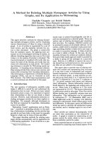
Fig. 2. General structure of CFG
(for par, seq fragments).
Fig. 3. General structure of CFG (for strict and
critical region fragments).
method call is then derived using the function
ReturnMessageStructure. For the OCL
constraints, type and attribute (the structure
including (mi, parameterList, returnValue))
are appended to the messge mi, and the
code to perform it is the function call
AttachConstraintInfo(). After creating the
corresponding node, the current node will
be connected to the created node, and
then this node is considered the current
node. In this way, CFG is generated
</div>
<span class='text_page_counter'>(7)</span><div class='page_container' data-page=7>
Algorithm 2 Analyzing elements of queue
Input: Class diagram CD,queue q,
curNode ∈ A
Output: exitNode ∈ Afunction processElement
(q: queue, CD: class diagram, curNode:A) :A
1:while queue != empty do
2: x= queue.pop();
3: if(x==fragment) and (x.type==’opt’ or ’alt’
or ’break’ or ’loop’) then
4: Create a DN ;
5: ConnectEdge(curNode,DN);
6: else if (x==message) then
7: begin
8: BN=CreateBlockNode()//BN is message
8: or a set of messages
9: for each message m ∈ B
10: get receiver class in r.clasName
11: msg=returnMsgStructure(CD,r.clasName,m)
12: attr=returnAttributeStructure(CD,r.clasName)
13: for all variables in m
14: attachAttributeInfor(attr,m);
14: //attach constraint c[i] to msg
15: end for
16: end for
17: ConnectEdge(curNode,DN);
18: exitNode=BN;
19: end;
20: else if(x==operand)and(x.guard!=null)then
21: attachGuardtoEdge()
22: curNode= DN;
23: else if(x==frag)and(x.type==’par’or’seq’)then
24: Create forkNode FN;
25: ConnectEdge(curNode,FN);
26: curNode= FN;
27: for each operand
28: create BN to coressponding msg;
29: isAsynToBN()//attach isAsyn to BN
30: end for
31:else if(x==’EOF’andx.type==’alt’or’opt’)then
31: //termination condition of frag alt or opt
32: Create merge node MN
33: ConnectEdge(curNode,MN);
34: exitNode=MN;
35:else if(x==’EOF’andx.type==’par’or’seq’)then
36: Create join node JN
37: ConnectEdge(curNode,JN);
38: exitNode=JN;
39:else if (x==’EOF’ and x.type==’loop’) then
40: attachLoopstoEdge()
40: //attach number of loops to Edge
41: ConnectEdge(curNode,DN);
42: curNode=DN;
43:end if
44:return exitNode;
45:end while;
Comparing with [2], a sequence of
messages in operands of par fragments is
equivalent with a BN while in this technique
each message corresponds to a BN. The
isAsyn property is attached to each BN if
the corresponding messages of threads in
seq or par fragment have sharing data or
lock mechanism (line 29). Therefore, a
method in Sect. 4 can generate all possible
scenarios by exploring the message sequence
with their possible interleaving of operands
in seq or par fragments. In addition, strict
and critical fragments are also applied to
generate CFG (Fig. 3).
4. Test Scenarios Generation
Given a CFG, an Algorithm is proposed
for generating test scenarios. The test
scenarios denote abstract test cases which
represent possible traces of executions. The
output from the scenario generation is a finite
set of scenarios which are complete paths
starting from the initial node to the final
node. Because it is usually impossible or
infeasible to test all possible paths (due to
limited testing resources), three concurrency
coverage criteria are given above to choose
that depending on the characteristics of each
project software. Both weak concurrency
coverage and moderate concurrency coverage
test the messages and control flows within
</div>
<span class='text_page_counter'>(8)</span><div class='page_container' data-page=8>
the systems do not address the issues of
the synchronization and sharing data, we
can select the weak coverage criterion or
moderate coverage criterion. The weak
concurrency coverage is one case of the
moderate coverage, so we propose Algorithm
3 to generate test scenarios following the
moderate coverage. Basic paths generated
using the Algorithm 3 are suitable for node
coverage and edge coverage of graph, but do
not address the issues of the synchronization
and data safety. When using that algorithm,
we cannot explore the message sequence with
their possible interleaving of operands in par
or seq fragments.
The proposed Algorithm 4 generates test
scenarios to improve the strong concurrency
coverage from CFG to solve that problem.
The algorithm constructs a path for each
thread of execution. At each step it appends
BN to the path t if curNode is BN. When
a DN is reached then on the basis of result
of decision guard condition, the path t is
appended respective true/false part up to MN.
If curNode is FN then sub paths representing
each thread of execution for that fork are
activated. The messages of operands in seq
or par fragment (having isAsyn property is
true) is a switch point of sub paths. The
point changes for the sub paths when BNs
are appended to the path t. That addition will
stop until all active sub paths for a given FN
are empty. When curNode is reached a final
node ( f ni), the path t is updated collection of
test scenarios T.
Comparing with depth first search (DFS)
and breadth first search (BFS) algorithm,
these new generated paths are given as
test scenarios for testing concurrency errors
in sequence diagram. In par or seq
Algorithm 3 Generating the test scenarios
following the moderate concurrency coverage
Input: Control-flow Graph G with initial
node in and final nodes are f ni
Output: T is a collection of test scenarios, t
is a test path
1: T = ∅; t = ∅;
2: curNode= in; //current node starts from in
3: repeat
4: move to next node;
5: if curNode== BN then
6: t.append(BN);
7: end if
8: if curNode== DN then
9: Append true part of BN up to MN in t
10: Append false part of BN up toMN in t
11: end if
12: if (curNode== FN) then
13: create sub path tifor each fork out flow;
14: append BN of each fork flow up to JN
15: in respective sub path ti;
16: end if
17: if (curNode== f ni) then
18: T= T + {t};
19: end if
20: until Graph end
fragment, selection of adequate switch points
for message interleaving of operands among
queues is more important. If there is no
switch point for each concurrent thread then
messages will execute one after another
in sequence.
This sequencing will lose concurrent
nature among messages. If there is a
</div>
<span class='text_page_counter'>(9)</span><div class='page_container' data-page=9>
sequence. Therefore, it will not lead to
any concurrency or synchronization error.
But the messages of concurrent threads have
the share common data or need any casual
order among them in different threads that
can be interleaved in restricted way. These
types of threads are called synchronized
threads. The synchronized threads need
careful selection of switch point in queues
to generate adequate test scenario. A proper
selection of switch point will generate a
feasible concurrent test sequence in presence
of concurrency.
A shared data of messages in operand or
threads using locking mechanism in par or
seq fragment need synchronized access. To
capture data safety errors, a switch point is
selected before a sharing data, after a sharing
data, before locking and after locking (for
example, bank transaction has two threads
in par fragment: Lock1-withdraw1-Unlock1;
Lock2-deposit2-Unlock2). These switch
points try to capture casual ordering errors
and data safety errors in the concurrent thread
implementation. A test scenarios generated
by algorithm 4 should be able to uncover
data safety error, concurrent execution should
able to detect inconsistent state of shared
data due to specific interleaving of execution.
A possible technique to generate such
interleaving is to switch execution of thread
inside critical section. A test sequence that
provides such specific interleaving, which
check for data inconsistency, is having data
safety error uncover capability.
Therefore, we could find the concurrency
errors such as safety and liveness property
of systems. The proposed method is applied
to systems for test scenarios generation and
found to be very effective in controlling the
test scenarios explosion problem.
All variables in the block node are
associated with constraint information which
is taken in class diagram. One representative
value for each variable on the test scenario is
to be selected. Therefore, messages in block
nodes along the test scenario correspond to a
parameterized operation call. Each outgoing
edge from a decision node contains one
predicate. Each test scenario must satisfy all
predicates along its path. Sect. 5 proposes
a method to generate test data for each the
scenario, special in case of loops.
5. Test Data Generation
The test scenarios obtained (as discussed in
the Sect. 4) denote the sequence of messages.
The sequence is a feasible sequence of
messages if we find test data (test input) to
satisfy all the constraints along the scenario.
Many current researches solve the equations
to find values that satisfy these constraints.
However, it is difficult to generate test data
for testing loops. The proposed method
solves that problem by finding values in the
test scenarios of CFG, using one predicate
at a time and reducing domains of variables
step by step. We develop the dynamic
domain reduction procedure [2] in case of
testing loops.
For each test scenario ti ( in set of test
scenarios T ) represents as a sequence of
nodes < ni1, ni2, ..., nig > where ni1 denotes
the initial node and nigdenotes the final node,
we need to find sub domain of test input
satisfying all the constraints along current
path ti such that the path reaches the final
</div>
<span class='text_page_counter'>(10)</span><div class='page_container' data-page=10>
key step in the procedure. The predicates
(on the branch edges) from DN are used to
form new constraints. The path tiis traversed,
a search process is used to split the domain
of some variables in an attempt to find a
set of values that allow the constraints to be
satisfied. GetSplit modifies the domains for
variables in a constraint so that (1) the new
domains satisfy the constraint and (2) the size
of the two domains is balanced. For example,
predicate is x > y with domains for x,y are
(0..50), the first attempt would be to make
the domain for x to be (26..50) and for y
is (0..25).
Given the initial domains of two variables
known as left and right variables that are
combined by a relational expression, if these
domains are non-intersecting, the predicate
may be either satisfied or is infeasible. If
the two domains define sets of values that
intersect, then getSplit modifies the two
domains such that the constraint is satisfied
for all pairs of values from the two domains.
The split point is found based on top and
bottom values of left and right domains.
There are the following four cases to consider
in Fig. 4.
Case 1:splitPt= (le f t.top − le f t.bot) ∗ pt + le f t.bot
Case 2:splitPt= (right.top − right.bot) ∗ pt + right.bot
Case 3:splitPt= (le f t.top − right.bot) ∗ pt + right.bot
Case 4:splitPt= (right.top − le f t.bot) ∗ pt + le f t.bot
The inputs to getSplit are domains
for two expressions (left and right
domains) and integer that indicates what
iteration of the search is being performed
(Indx = 1, 2, 3, 4,...) with exp satisfies:
2exp <sub>≤ Indx ≤ 2</sub>exp+ 1
Therefore, pt= (2exp−(2∗(2<sub>2</sub>expexp−1)−1))
Result, pt = (1<sub>2</sub>, 1<sub>4</sub>,3<sub>4</sub>,1<sub>8</sub>,3<sub>8</sub>,...)
The synthesis test data generation
procedure includes the following steps:
Fig. 4. Compute splitPt depending on
domains of variables.
Choose test scenario ti, a sequence of
nodes < ni1, ni2, ..., nig >. If node ni is a
DN, it is marked and encountered. Later,
the procedure uses reading predicate on
the branch edge and reducing domains of
variables by using above getSplit. If node
ni is not a DN, the procedure moves to
next node. When using getSplit, the value
of pt is initially got to 1<sub>2</sub> and depending
domains of left and right variables to get
the new domains for variables. A split
point is returned, the domains of left and
right variables are adjusted. If the new
domain values satisfy the predicate then the
procedure continues with the next node of the
scenario ti until the final node is reached. If
the new domains do not satisfy the constraint
the value of pt is changed to 1<sub>4</sub> and a different
split is found. If there have been too many
attempts to find a feasible split point (more
than k split points), the procedure goes to the
previous DN in the scenario ti. If there are
</div>
<span class='text_page_counter'>(11)</span><div class='page_container' data-page=11>
procedure gives up on this path and goes to
the next path in T . Normally when we test
loops, test scenarios will be tested in some
cases with 1, 2, random n, max, min times
of specified loops. If the test scenario is
traversed, the DN is marked and encountered
and then variables are checked dynamically
(the maximum or minimum numbers of loops
which are parameters of loop fragments are
attached in edges of graph). If the variable
does not satisfy the constraint, the procedure
exits the loop and continues traversing the
test scenario on the node after the loop. The
reduced domain at the end of the procedure
denotes a feasible domain of values for a
test scenario.
In the test data generation procedure, loops
are handled dynamically. The procedure finds
all the scenarios that contain at most one
loop structure. It then marks those DNs
that affect whether another iteration of the
loop is made. Then as the test scenario
is traversed, when the DN is encountered,
the loop constraint and variables are checked
dynamically to decide whether to continue
with another iteration. Comparing with [2], if
variables always satisfy in next iteration, our
procedure exits the loops to generate test data
when the DN is encountered in case of 1, 2,
random n, max and min loops.
In [2, 5] for loop fragment, the coverage
criterion satisfies at least one scenario
reaching the loop and the body of the loop is
only executed once. Our method is that test
scenario containing test data are generated if
satisfying the constraints along the scenario
in case number of loops 0, 1, 2, random n
and max, min of loops.
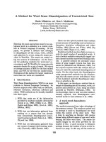
Fig. 5. Figure showing architecture
of SequenceCocur.
Execution time: Algorithmic analysis
of algorithms are complicated that is
exceedingly difficult. The excecution time of
the procedure depends upon the number of
decision nodes (D), the number of paths (T ),
and the constant k (split points). Moreover,
if the procedure has to go through k attempts
at each decision node, then that is k split
attempts at the first decision, then k splits at
the second decision for every attempt at the
second decision, and so on, for a total of kD
split attemps. So the running time is T ∗ kD<sub>.</sub>
Although the worst–case running time
is exponential, the worst case can seldom
be expected to be achieved in practice.
Moving through the control fow graph
dynamically allows path constraints to be
resolved immediately, which is more efficient
both in space and time, and more often
successful than constraint-based testing. The
dynamic nature of this procedure also allows
certain improvements to be made in the
handling of arrays, loops, and expressions.
This procedure incorporates elements
from the constraint–based testing domain
reduction procedure, symbolic evaluation,
</div>
<span class='text_page_counter'>(12)</span><div class='page_container' data-page=12>
approach. It integrates constraint satisfaction,
symbolic evaluation, and a novel search
process into one dynamic process. As
compared with previous automatic test data
generation procedures, we believe that the
dynamic domain reduction procedure can
be expected to be more likely to find a
test case when a test case exists, and that
implementations can be more effective
and efficient.
6. Experiments
A tool named SequenceConcur to support
the proposed method has been implemented.
We report on a case study conducted to
examine the method, and mutation analysis
was used to evaluate its effetiveness.
Comparing with [13], we develop an
algorithm for generating test cases with
respect to the given concurrency coverage
criteria and implement the tool to support the
proposed method.
6.1. Tool Support
In this section we discuss the results
obtained by implementing the proposed
method. The method is implemeted using
JAVA and JDK version 1.8. We have
developed the method for generating test
cases automatically from UML sequence
diagrams and OCL in a tool. The architecture
of SequenceConcur is shown in Fig. 5.
The Tool consists of 1936 lines of code and
has the following functionality:
(i) Preprocessing: It imports the UML
sequence diagrams and OCL in class
diagrams (in XMI format). We
used Enterprise Achitect version 11 to
Fig. 6. Generated test paths for moderate
coverage criterion.
produce the UML design artefact. The
tool was developed using the proposed
recursive algorithm (in Sect. 3) for
generating CFG.
(ii) Generating test senarios: It generates
test scenarios from CFG with respect to
different concurrency coverage criteria
and presents the generated scenarios for
further analysis.
(iii) Generating test data: It creates test
data for each test scenario by improving
dynamic domain reduction procedure
[4]. The proposed procedure solves this
test data for testing loops.
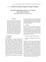
The weak concurrency coverage is one
case of the moderate coverage, so the tool
only presents moderate coverage. The
moderate coverage path tab (as shown in
Fig. 6) presents the generated test scenarios
satisfying the moderate coverage criterion
and the strong coverage path tab shows
the generated test scenarios satisfying the
improved strong coverage criterion (as shown
in Fig. 7).
6.2. Case study
</div>
<span class='text_page_counter'>(13)</span><div class='page_container' data-page=13>
Fig. 7. Generated test paths for strong
coverage criterion.
and class diagram using an example of a bank
transaction. A bank object is a main thread
of the application that creates two additional
threads such as thread1, thread2. These two
threads handle the money transfer between
two accounts, saving account (accSaving)
and current account (accCurrent). The
operations of a money transfer are enclosed
in a par combined fragment that represents a
concurrent execution of the messages in this
fragment. However, we assume that in the
current account type users can withdraw up to
5 times per day. In our study, we developed
the case study which is relatively small in
size but which covered most major improved
features. Figure 8 represents UML sequence
diagram for account transfer functionality.
For the sake of brevity, the class diagram
(as shown in Fig. 9) shows only the specific
classes that are involved in that function.
Test scenarios generation: The proposed
algorithm traverses the CFG to generate test
scenarios (in Sect. 4). For concurrent system,
by using Algorithm 4 test scenarios would
be able to uncover some of the concurrency
issues. The account transfer functionality
identifies the quality of the test scenarios
generated by DFS, BFS and our method to
uncover the concurrency errors (Table 1).
Fig. 8. The sequence diagram for Account Transfer in
Bank system.
Working of the test data generation
algorithm: consider the test scenario
described by T3=
(Start-FN-M5-M6-M1-M2-DN-M7-DN-M8-M3-M4-JN-End),
we illustrate test data generation for the
scenario T3. The predicates are shown on
their associated edges, and the constraints
and data type of variable are attached in
block node. The variables amount of money
being withdrawn of two account type are
x,y and the balance of account is balance.
All variables from class diagram are set
with integer domain. The initial domains
of input variables x,y and balance are:
x,y:[50,50000] and balance:[100,65535]
(because balance ≥ 100 and balance is
integer variable).
Assume that the test path T3 with 2 loops,
our algorithm marks and encounters decision
node DN that traversed. If DN is 2, the
test path is:
Start-M5-M6-M1-M2-DN-M7-DN-M7-DN-M8-M3-M4-End The sub path
of M5-M6-M1-M2 introduces no change to
the input variables. To take the branch
from node DN to M7, the predicate y <
</div>
<span class='text_page_counter'>(14)</span><div class='page_container' data-page=14>
Fig. 9. The class diagram and constraint OCL for
Account Transfer.
[100, 65535]. Therefore, domain of variables
indicate split point in the fourth case, and
splitPt = (right.top − le f t.bot) ∗ pt +
le f t.bot = (65535 − 50) ∗ 1/2 + 50 =
32792, so y : [50, 32792]; balance :
[32793, 65535]. Traverse block node M7,
withdraw(y) because the smallest amount of
money withdrawn is 50, so balance reduces
50, thus balance: [32743, 65485].
The next time through the loop, we have
the same predicate, domain of variables is
in the fourth case splitPt = (65485 −
50) ∗ 1/2 + 50 = 32767, thus y :
[50, 32767] and balance : [32768, 65535].
Get on traversing M7, withdraw(y) because
the smallest amount of money withdrawn is
50, so balance reduces 50, thus balance :
[32718, 65485].
The final time through the loop, the branch
from DN to M8, that domains of variables are
in the fourth case and splitPt= (65485−50)∗
1/2+ 50 = 32767, because the predicate y ≥
balance, thus value of y is 32767 and domain
of balance is [32718, 32766]. Therefore, for
test scenario T3 reduced domain of test data
are: y= 32767;balance : [32718, 32766] and
x: [50, 50000].
6.3. Evaluation
In this section, we attempt to prove the
fault- detection capability of the test suite
generated using the proposed method.
6.3.1. Metrics
By using the mutation score (MS), we
measure the effectiveness of the proposed
method. The MS indicates the adequacy of
a test suite for the system under testing.
6.3.2. Experimental procedure
We used SequenceConcur tool to parse
the UML sequence diagram (in an XMI file)
and OCL for bank transaction. During the
transformation, all branches and concurrent
flows were represented as CFG. The tool
generated a set of test scenarios from the
graphs based on a given coverage criterion.
Test data are generated by using the
Algorithm in Sect. 5 (special in case of testing
loops), from which we selected only those
satisfying the generated test scenarios to be
in the test suite. As a result, we selected
20 test cases for each test scenario when
the improved strong coverage criterion was
used, four test scenarios were created in
our experiments.
Seeding faults: muJava [14] was used to
randomly seed faults into the Java program
for bank transaction. Using the muJava
</div>
<span class='text_page_counter'>(15)</span><div class='page_container' data-page=15>
Table 1. Test scenarios generated by DFS, BFS and our algorithm
and last column indicates data safety error uncover capability
Algorithm Test scenarios Error
uncover
capability
DFS Start-FN-M1-M2-M3-M4-M5-M6-DN-M7-DN-M8-JN-End No
Start-FN-M5-M6-DN-M7-DN-M8-M1-M2-M3-M4-JN-End No
BFS Start-FN-M1-M5-M2-M6-M3-DN-M7-DN-M4-M8-JN-End Yes
Start-FN-M5-M1-M6-M2-DN-M7-DN-M3-M8-M4-JN-End Yes
Our algorithm
Start-FN-M1-M5-M2-M3-M4-M6-DN-M7-DN-M8-JN-End(T1)
Yes
Start-FN-M1-M5-M2-M3-M4-M6-DN-M8-JN-End(T2) Yes
Start-FN-M5-M6-M1-M2-DN-M7-DN-M8-M3-M4-JN-End(T3)
Yes
Start-FN-M5-M6-M1-M2-DN-M8-M3-M4-JN-End(T4) Yes
Executing tests and collecting the results:
we next applied each test in the test suite to
both the original program and the mutants,
comparing with the outputs. If the output
was the same, then the current test passed;
otherwise, a fault was detected.
6.3.3. Results and analysis
Data safety error uncover capability: in
our case study, the messages m2 and m6 in
par fragment have shared data, and safety of
data is more important. Test scenarios are
generated by the algorithm that should be
able to uncover data safety errors. We use
and compare DFS, BFS and our algorithm
in generating the test scenarios (in Table 1)
from CFG.
DFS algorithm generates test scenarios
including test sequences that are not capable
of finding data safety errors because it does
not allow interleaving between the messages
of two operands in par fragments. The
test scenarios are generated by BFS and our
algorithm that are capable of finding data
safety errors.
However, BFS algorithm does not generate
the test sequences in case of zero iteration
loop while our method uses with two parts,
false part and true part that means zero and
more than one iteration. Test data are also
considered to get on with 2, random n and
max, min loops.
Fault– detection capability: In order to
study the impact of the test suite size on
the effectiveness of the proposed method,
we varied the size to be 2, 10, 20 and
30 test cases per scenario. We further
compare the fault- detection effectiveness of
the proposed method with that of random
testing, comparing their MS scores for the
same numbers of test cases.
</div>
<span class='text_page_counter'>(16)</span><div class='page_container' data-page=16>
Table 2. The MS results using the strong concurrency coverage criterion for each test scenario
Level Number of test
cases
Test
scenario 1
Test
scenario 2
Test
scenario 3
Test
scenario 4
Method-level size= 2 51.2% 40.5% 45.7% 50.2%
size= 10/20/30 56.5% 55.7% 47.7% 60.4%
Class-level size= 2/10/20/30 74.5% 74.5% 81.5% 81.5%
Table 3. The mutation score MS results of our method and the random method
Our method Random Method
Number of test
cases
Level Total
mutants
Total
killed
mutants
MS Killed mutants MS
size= 2
Method-level 351 261 74.3% 139 39.6%
Class-level 26 26 100% 23 88.4%
Total 377 287 76.2% 162 42.9%
size= 10/20/30
Method-level 351 266 75.7% 153 43.5%
Class-level 26 26 100% 26 100%
Total 377 292 77.5% 179 47.4%
(i) For both method-level and class-level
faults, the generated test scenarios show
a good fault-detection effectiveness. The
generated test case were able to detect more
than 40.5% of method-level faults and were
able to detect more than 74.5% of the
class-level faults.
(ii) the test suites are derived for different
test scenarios which have a different
fault-detection capability. Because the evaluation
results for different test suite sizes are the
same in case of 10, 20, 30 test cases per each
scenario for both method-level faults and
class-level faults, our method does not need a
large number of test cases for each scenario.
Table 3 presents the MS results of both our
method and the random method. From the
table, we can observe the following:
(i) for the same sizes, test suites generated by
our method achieve higher mutation scores
than those achieved by the random method,
with the differences being more prominent
when the size is small (with a size of two,
their MS are 76.2% and 42.9%, respectively).
(ii) regardless of test suite size, the test suites
generated by our method can detect 100%
class-level faults while it can detect only
88.4% by the random method.
The experimental results show that, the
test suite generated using our method can
detect more than 76% of seed faults with a
very small size of test suite (one test case
per scenario). Furthermore, more than 74%
of method-level faults and 100% of
class-level faults can be detected by the generated
</div>
<span class='text_page_counter'>(17)</span><div class='page_container' data-page=17>
method achieved a higher mutation score
than random testing. These results indicate
that the proposed method is both effective
and efficient.
Algorithm 4 Generating the test scenarios to
improve the strong concurrency coverage
Input: Control-flow Graph G with initial
node in and final nodes are f ni
Output: T is a collection of test scenarios, t
is a test path
1: T = ∅; t = ∅;
2: curNode= in; //current node starts from in
3: repeat
4: move to next node;
5: if (curNode== BN) then
6: t.append(BN);
7: end if
8: if (curNode==DN and Branch is TRUE)
then
9: Append t with true part BN to MN;
10: else
11: Append t with false part BN to MN;
12: end if
13: if (curNode== FN) then
14: active all sub paths of FN;
15: repeat
16: Select random sub path;
17: Append t with node up to before or
after node having isAsyn //message
having isAsyn (true) is a switch point
18: until all sub paths are empty
19: end if
20: if (curNode== f ni) then
21: T= T + {t};
22: end if
23: until Graph end
7. Conclusions
The paper presented the automated
test data generation method based UML
sequence diagrams, class diagrams and OCL.
The method supports UML 2.0 sequence
diagrams including eight kinds of combined
fragments.The key idea of this method is to
generate all possible test scenarios in case of
exploring the message sequence with their
possible interleaving in par or seq fragments.
The test scenarios are generated to avoid
test explosion by selecting switch points.
Therefore, concurrency errors of systems can
be found. In addition, test data generation for
testing loop fragments in case of iterations 0,
1, 2, random n and max, min loops.
In some current approaches, test data are
generated in case of body of loop that is
only executed once. The method supports
different coverage criteria and can therefore
test concurrent processes effectively. Finally,
we have implemented the tool to support
the proposed method and conducted the
case study (bank transaction) to validate its
feasibility and effectiveness.
We are investigating to determine
infeasible or feasible test scenarios when
there have no input data for them to be
executed. We also are going to extend
the proposed method for other UML
diagrams (e.g., state-chart diagrams, activity
diagrams). Moreover, we would like to
further investigate and evaluate the
fault-detection effectiveness, and costs, of the
proposed concurrency coverage criteria.
Acknowledgments
</div>
<span class='text_page_counter'>(18)</span><div class='page_container' data-page=18>
References
[1] M. Utting, B. Legeard, Practical Model-Based
Testing: A Tools Approach, Morgan Kaufmann
Publishers Inc., San Francisco, CA, USA, 2006.
[2] A. Nayak, D. Samanta, Automatic test data
synthesis using uml sequence diagrams, Journal
of Object Technology 9 (2) (2010) 115–144.
[3] M. Shirole, R. Kumar, Testing for concurrency
in uml diagrams, SIGSOFT Softw. Eng. Notes
37 (5) (2012) 1–8.
[4] M. Dhineshkumar, Galeebathullah, An approach
to generate test cases from sequence diagram,
in: Proceedings of the 2014 International
Conference on Intelligent Computing
Applications, ICICA ’14, IEEE Computer
Society, Washington, DC, USA, 2014, pp.
345–349.
[5] B.-L. Li, Z.-s. Li, L. Qing, Y.-H. Chen, Test case
automate generation from uml sequence diagram
and ocl expression, in: Proceedings of the
2007 International Conference on Computational
Intelligence and Security, CIS ’07, IEEE
Computer Society, Washington, DC, USA, 2007,
pp. 1048–1052.
[6] O. M. Group, The Unified Modeling Language
UML 2.0 Technical Report formal/06-04-04, The
Object Management Group (OMG), 2006.
[7] M. Khandai, A. Acharya, D. Mohapatra, A
novel approach of test case generation for
concurrent systems using uml sequence diagram,
in: Electronics Computer Technology (ICECT),
3rd International Conference, Vol. 1, 2011, pp.
157–161.
[8] C. ai Sun, Y. Zhao, L. Pan, X. He, D. Towey,
A transformation-based approach to testing
concurrent programs using uml activity
diagrams, Software: Practice and Experience.
[9] C. ai Sun, A transformation-based approach
to generating scenario-oriented test cases from
uml activity diagrams for concurrent applications
(2008) 160–167.
[10] S. C-A, W. G, C. K-Y, C. TY, Distribution-aware
mutation analysis, in: Proceedings of 9th IEEE
International Workshop on Software Cybernetics
(IWSC 2012), IEEE Computer Society, Izmir,
Turkey, 2012, pp. 170–175.
[11] A. JH, B. LC, L. Y, Is mutation an appropriate
tool for testing experiments, in: Proceedings of
the 27th International Conference on Software
Engineering (ICSE 2005), IEEE Computer
Society, St. Louis, Missouri, 2005, pp. 402–411.
[12] H. Minh Duong, L. Khanh Trinh, P. N.
Hung, An assume-guarantee model checker
for component-based systems, in: The 10th
IEEE-RIVF International Conference on
Computing and Communication Technologies,
2013, pp. 22–26.
[13] T. D. Vu, P. N. Hung, V. H. Nguyen, A
Method for Automated Test Data Generation
from Sequence Diagrams and Object Constraint
Language, in: Proceedings of the Sixth
International Symposium on Information and
Communication Technology, ACM, Hue City,
Viet Nam, 2015, pp. 335–341.
</div>
<!--links-->