Lab 9.3.6 Configuring Inter-VLAN Routing
Bạn đang xem bản rút gọn của tài liệu. Xem và tải ngay bản đầy đủ của tài liệu tại đây (145.49 KB, 7 trang )
1 - 7 CCNA 3: Switching Basics and Intermediate Routing v 3.0 - Lab 9.3.6 Copyright 2003, Cisco Systems, Inc.
Lab 9.3.6 Configuring Inter-VLAN Routing
Objective
• Create a basic switch configuration and verify it.
• Create multiple VLANs, name them and assign multiple member ports to them.
• Create a basic configuration on a router.
• Create an 802.1q trunk line between the switch and router to allow communication between
VLANs.
• Test the routing functionality.
Background/Preparation
When managing a switch, the Management Domain is always VLAN 1. The Network Administrator's
workstation must have access to a port in the VLAN 1 Management Domain. All ports are assigned
to VLAN 1 by default. This lab will also help demonstrate how VLANs can be used to separate traffic
and reduce broadcast domains.
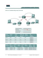
Cable a network similar to the one in the diagram. The configuration output used in this lab is
produced from a 2950 series switch. Any other switch used may produce different output. The
following steps are to be executed on each switch unless specifically instructed otherwise.
Instructions are also provided for the 1900 Series switch, which initially displays a User Interface
Menu. Select the “Command Line” option from the menu to perform the steps for this lab.
Note: The router used must have a Fast Ethernet interface in order to support trunking and inter-
VLAN routing. The 2500 series router cannot be used for this lab.
2 - 7 CCNA 3: Switching Basics and Intermediate Routing v 3.0 - Lab 9.3.6 Copyright 2003, Cisco Systems, Inc.
Start a HyperTerminal session.
Note: Go to the erase and reload instructions at the end of this lab. Perform those steps on all
switches in this lab assignment before continuing.
Step 1
Configure the switch
Configure the hostname, access, and command mode passwords, as well as the management LAN
settings. These values are shown in the chart. If problems occur while performing this configuration,
refer to the Basic Switch Configuration lab.
Step 2 Configure the hosts attached to the switch
Configure the hosts using the following information.
a. For the host in port 0/5:
IP address 192.168.5.2
Subnet mask 255.255.255.0
Default gateway 192.168.5.1
b. For the host in port 0/9:
IP address 192.168.7.2
Subnet mask 255.255.255.0
Default gateway 192.168.7.1
Step 3 Verify connectivity
a. To verify that the host and switch are correctly configured, ping the switch from the hosts.
b. Ping the switch IP address from the hosts.
c. Were the pings successful?
__________________________________________________
d. Why or why not?
__________________________________________________
Step 4 Create and name two VLANs
Enter the following commands to create and name two VLANs:
Switch_A#vlan database
Switch_A(vlan)#vlan 10 name Sales
Switch_A(vlan)#vlan 20 name Support
Switch_A(vlan)#exit
1900:
Switch_A#config terminal
Switch_A(config)#vlan 10 name Sales
Switch_A(config)#vlan 20 name Support
Switch_A(config)#exit
Step 5 Configure VTP protocol
Assigning ports to VLANs must be done from the interface mode. Enter the following commands to
add ports 0/5 to 0/8 to VLAN 10:
Switch_A#configure terminal
Switch_A(config)#interface fastethernet 0/5
3 - 7 CCNA 3: Switching Basics and Intermediate Routing v 3.0 - Lab 9.3.6 Copyright 2003, Cisco Systems, Inc.
Switch_A(config-if)#switchport mode access
Switch_A(config-if)#switchport access vlan 10
Switch_A(config-if)#interface fastethernet 0/6
Switch_A(config-if)#switchport mode access
Switch_A(config-if)#switchport access vlan 10
Switch_A(config-if)#interface fastethernet 0/7
Switch_A(config-if)#switchport mode access
Switch_A(config-if)#switchport access vlan 10
Switch_A(config-if)#interface fastethernet 0/8
Switch_A(config-if)#switchport mode access
Switch_A(config-if)#switchport access vlan 10
Switch_A(config-if)#end
1900:
Switch_A#config terminal
Switch_A(config)#interface ethernet 0/5
Switch_A(config-if)vlan static 10
Switch_A(config-if)#interface ethernet 0/6
Switch_A(config-if)vlan static 10
Switch_A(config-if)#interface ethernet 0/7
Switch_A(config-if)vlan static 10
Switch_A(config-if)#interface ethernet 0/8
Switch_A(config-if)vlan static 10
Switch_A(config-if)#end
Step 6 Assign ports to VLAN 20
Enter the following commands to add ports 0/9 to 0/12 to VLAN 20:
Switch_A#configure terminal
Switch_A(config)#interface fastethernet 0/9
Switch_A(config-if)#switchport mode access
Switch_A(config-if)#switchport access vlan 20
Switch_A(config-if)#interface fastethernet 0/10
Switch_A(config-if)#switchport mode access
Switch_A(config-if)#switchport access vlan 20
Switch_A(config-if)#interface fastethernet 0/11
Switch_A(config-if)#switchport mode access
Switch_A(config-if)#switchport access vlan 20
Switch_A(config-if)#interface fastethernet0/12
Switch_A(config-if)#switchport mode access
Switch_A(config-if)#switchport access vlan 20
Switch_A(config-if)#end
1900:
Switch_A#config terminal
Switch_A(config)#interface ethernet 0/9
Switch_A(config-if)vlan static 20
Switch_A(config-if)#interface ethernet 0/10
Switch_A(config-if)vlan static 20
Switch_A(config-if)#interface ethernet 0/11
Switch_A(config-if)vlan static 20
Switch_A(config-if)#interface ethernet 0/12
Switch_A(config-if)vlan static 20
Switch_A(config-if)#end
4 - 7 CCNA 3: Switching Basics and Intermediate Routing v 3.0 - Lab 9.3.6 Copyright 2003, Cisco Systems, Inc.
Step 7 Display the VLAN interface information
a. On Switch_A, type the command show vlan at the privileged EXEC prompt as follows:
Switch_A#show vlan
b. Are ports assigned correctly?
_________________________________________________
Step 8 Create the trunk
On Switch_A, type the following commands at the Fast Ethernet 0/1 interface command prompt.
Note that Ethernet 0/1 and the other access ports on a 1900 switch only support 10 Mbps Ethernet
and cannot be used as trunk ports. The trunk ports (if present) on a 24-port 1900 are typically Fast
Ethernet 0/26 and 0/27.
Switch_A(config)#interface fastethernet0/1
Switch_A(config-if)#switchport mode trunk
Switch_A(config-if)#end
2900:
Switch_A(config)#interface fastethernet0/1
Switch_A(config-if)#switchport mode trunk
Switch_A(config-if)#switchport trunk encapsulation dot1q
Switch_A(config-if)#end
1900:
Switch_A#config terminal
Switch_A(config)#interface fastethernet0/26
Switch_A(config-if)#trunk on
Step 9 Configure the router
a. Configure the router with the following data. Note that, in order to support trunking and inter-
VLAN routing, the router must have a Fast Ethernet interface.
Hostname is Router_A
Console, VTY, and enable passwords are cisco.
Enable secret password is class.
b. Then configure the Fast Ethernet interface using the following commands:
Note: If working with a 1900 switch, replace the “dot1.q” encapsulation with “isl” in the following
router configuration commands.
Router_A(config)#interface fastethernet 0/0
Router_A(config-if)#no shutdown
Router_A(config-if)#interface fastethernet 0/0.1
Router_A(config-subif)#encapsulation dot1q 1
Router_A(config-subif)#ip address 192.168.1.1 255.255.255.0
Router_A(config-if)#interface fastethernet 0/1.2
Router_A(config-subif)#encapsulation dot1q 10
Router_A(config-subif)#ip address 192.168.5.1 255.255.255.0
Router_A(config-if)#interface fastethernet 0/0.3
Router_A(config-subif)#encapsulation dot1q 20
Router_A(config-subif)#ip address 192.168.7.1 255.255.255.0
Router_A(config-subif)#end
5 - 7 CCNA 3: Switching Basics and Intermediate Routing v 3.0 - Lab 9.3.6 Copyright 2003, Cisco Systems, Inc.
Step 10 Save the router configuration
Step 11 Display the router routing table
a. Type show ip route at the privileged EXEC mode prompt.
b. Are there entries in the routing table?
___________________________________________
c. What interface are they all pointing to?
__________________________________________
d. Why is there not a need to run a routing protocol?
__________________________________
Step 12 Test the VLANS and the trunk
Ping from the host in Switch_A port 0/9 to the host in port 0/5.
a. Was the ping successful?
___________________________________________________
b. Why?
__________________________________________________________________
Ping from the host in Switch_A port 0/5 to the switch IP 192.168.1.2.
c. Was the ping successful?
___________________________________________________
Step 13 Move the hosts
a. Move the hosts to other VLANs and try pinging the management VLAN 1.
b. Note the results of the pinging.
__________________________________________________________________________
__________________________________________________________________________
__________________________________________________________________________
__________________________________________________________________________
__________________________________________________________________________
Once the steps are complete, logoff by typing exit, and turn all the devices off. Then remove and
store the cables and adapter.