Analysis of Permanent Magnet Synchronous Machine for Integrated StarterAlternatorBooster Applications
Bạn đang xem bản rút gọn của tài liệu. Xem và tải ngay bản đầy đủ của tài liệu tại đây (1.12 MB, 5 trang )
2015 International Conference on Electrical Drives and Power Electronics (EDPE)
The High Tatras, 21-23 Sept. 2015
Analysis of Permanent Magnet Synchronous Machine
for Integrated Starter-Alternator-Booster Applications
Florin Nicolae Jurca, Mircea Ruba, Claudia Martis
Department of Electrical Machines and Drives
Technical University of Cluj-Napoca
Romania
, ,
the internal combustion engine for a short period of time
(maximum 2 minutes), in situations where additional
mechanical energy is necessary (overruns, ramps etc) [1, 2].
The ISAB can be connected to a gasoline or diesel engine
either directly through crankshaft or indirectly through belt
drive, and they are accordingly called the belt-driven starter
alternator (BAS) and normal ISAB, respectively. The
permanent synchronous machine with outer rotor is an
innovative solution of direct connection to the internal
combustion engine in both cases in the context of minimal
mechanical losses. Comparative whit other types of electrical
machines, the permanent magnet (PM) synchronous machines
have some important advantages like high power density, high
efficiency and the possibility to work in high overload [3].
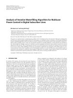
The present paper approaches the design and analysis of a
special topology of interior permanent magnet synchronous
machine (IPMSM) suited for automotive application, shown in
Fig.1. This machine is characterized by anisotropic rotor, that
is benefit when flux-weakening operations are required. The
motor torque is due to two components: one is due to the PM
flux and the other to the rotor saliency. In addition, the
anisotropic rotor is advantageous in order to detect the rotor
position without using a position sensor [3].
Abstract—In the last decade due to their high efficiency and
reliability, permanent magnet synchronous machine are widely
used in automotive applications. There are two main reasons for
this trend: the reduction of the fuel consumption and the increase
of the travel comfort. In this study we consider the approaches of
electromagnetic design of a special topology of permanent
synchronous machine (radial flux machine with outer rotor)
suited for automotive applications. The study design requires
some analytical analysis, followed by a numerical one in order to
attain the performances of the proposed machine in all three
cases (starter-alternator-booster). A thermal analysis is required
in order to determine the thermal requirements for the
automotive applications
Keywords— permanent magnet motor; electromechanical system;
hybrid vehicule
I. INTRODUCTION
Current research efforts related to electric cars have
problems mainly related to the accumulation of electricity. In
this context (low autonomy, lack of fast charging stations) the
use of this type of machine is limited to urban trails. Initially
considered as a transition between conventional vehicles and
the electric ones, the hybrid vehicles remain an alternative that
is gaining more ground by combining the advantages of both
types of vehicles. Of the two types of series and parallel
hybrid vehicles, alternative series provides a simpler
connection between the two engines and transmission
powertrain. Passing to the present path of development of
hybrid vehicles involves increasing the role in the operation of
the electrical machines by increase its power and
"responsibility" (starter-alternator-booster). The first steps
were be made by using a single electric machine as a
generator (alternator) and motor (starter) for starting the
internal combustion engine, but for a hybrid car a second
electrical machine is used for the electric propulsion. The
simplification of this structure involves the use of a single
electric machine incorporating three operating modes: starteralternator-booster (ISAB). In this case ISAB will initially be
able to start internal combustion engine, then when turned on
will switch to a generator and will supply the electricity
consumers and the electricity storage system. Due to the
control strategies used, electrical machine is capable to move
quickly from generator to motor (booster) and back to help
Fig.1. Structure of the ISAB: 42-slot 14 pole IPM machine.
978-1-4673-7376-0/15/$31.00 ©2015 IEEE
EDPE 2015
272
2015 International Conference on Electrical Drives and Power Electronics (EDPE)
The High Tatras, 21-23 Sept. 2015
For no-load condition, the air-gap magnetic flux density
distribution is depicted in Fig. 4, giving an average value of
0.72 T.
A preliminary design procedure will be performed using
SPEED program and the results will be implemented in a FEM
based software in order to analyze the performances of the
machine: magnetic field density, induced emf, torque and
current. After that a thermal analysis is required because the
thermal behavior can drastically influence the machine's
performances. Thus a special attention should be paid on the
heat transfer within the active and non-active parts of the
machine.
II. PRELIMINARY DESIGN
The initial phase of the design was conducted using SPEED
software. The SPEED software allows very fast performance
estimation of the electrical machine. The software is mainly
based on analytical computations. The motor structures were
refined using ranging analysis that helps to determine the
influence of geometrical and electrical parameters on the
motor performance.
In order to improve the electrical machines performances,
several winding topologies will be analyzed. The output
performances of the studied motor are: P – 7 (kW); rated
voltage Un – 72 (V); rated speed nn – 500 rpm; pole pair
number p – 14. The rotor has three flux barriers per pole. The
dimensions of the PMs are equal to 2 x 10 mm, 2.5 x 16 mm,
3 x 18 mm. The obtained main dimensions and the results for
the operation at rated point are shown in Table1.
Fig. 2. Map of flux density.
TABLE I. GEOMETRIC AND RESULTS PARAMETERS FOR THE
DESIGED MACHINE
Stator outer diameter [m]
0.210
Rotor outer diameter [m]
0.150
Shaft diameter
0.110
Stack length [m]
0.150
Slot area [mm2]
89.3
Air-gap [m]
0.0005
Slot number
42
Slot depth [m]
0.014
Tooth width [m]
0.006
Back iron height [m]
0.0147
Pole number
14
Air-gap flux density [T]
1
Rates speed [rot/min]
500
Phase emf [V]
42
Rated current [A]
50
Current density [A/ mm2]
15.75
Power factor [%]
0.89
Efficiency [%]
90
Torque [N*m]
155
PM residual flux density [T]
1.42
Fig.3. Flux lines distribution.
1.5
1
III. MAGNETIC FIELD ANALYSIS.
0.5
B [T]
The finite element method (FEM) is a powerful tool for the
design of the electrical machines and others electromagnetic
devices. FEM is a simple, robust and efficient widely used
method of obtaining a numerical approximate solution for a
given mathematical model of the machine. This analysis has
been carried out using Flux2D software.
The magnetic flux density map in the cross-section of the
machine is presented in Fig.2 and the flux lines distribution in
Fig. 3.
0
-0.5
-1
-1.5
0
40
80
120
160
200
rotor angle [o]
240
Fig. 4. Air-gap magnetic flux density.
EDPE 2015
273
280
320
360
2015 International Conference on Electrical Drives and Power Electronics (EDPE)
The High Tatras, 21-23 Sept. 2015
The regime operation in load condition will be simulated in
order to obtain de torque value at rated speed.
190
180
T orque [N *m ]
170
160
150
140
130
120
110
100
0.005
0.01
0.015
Time [s]
0.02
0.025
0.03
Fig. 5. Torque variation in time.
In order to evaluate the efficiency of the machine in starter
an alternator mode the iron losses was computed for obtained
the efficiency map of ISAB. The machine efficiency for over
the entire torque (current)/speed of starter and alternator
regime, considering the copper losses (80oC) can be seen in
Fig.6 and Fig.7. From this efficiencies map, the machine
losses can be extracted and used as input data for a thermal
simulation of the machine.
9 2 .0 2
90 .4 3 81
180
86
71
88 .8 4 76
87 .2 5
85 .66 67
140
84 .07 62
82 .48 57
7 9 .30 48
77 .7 1 4 3
76 .1 2 3 8
74 .53 33
72 .94 29
7 1 .35 2 4
6 9 .76 19
68 .1 7 1 4
66 .5 8 1
64 .9 9 05
160
Fig.8. Skewing the IPMSM: flux density repartition
The geometry of the IPMSM 42/14 was drawn in 2D and after
that we have considered an angle of incline of 1 slot (360/42).
The effect on rotor sheets incline, as well as the core flux
density repartition, is shows in Fig. 8. Now, one can verify the
torque repartition for the skewed machine, Fig.9. The torque
varies between 153 and 158, meaning that the torque ripple
corresponds to 3.2%. This is an important decrease of torque
ripple content. This gain can be decisive while preparing the
control of the IPMSM.
160
40
.4 3
76
90
120
.0 2
86
93
150
200
250
300
Speed [rpm]
400
IPMSM
IPMSM-skewed
20
0
90 .43 81
350
80
40
95 .20 95
93 .61 9
92 .02 86
100
60
95
95 .20
9
.61
90.43 81
100
Torque [N*m]
.43
76
.84
92
90
71
.8 4
.2 5
87
52 7 2 6 7
.89 8 5 7 6 66
8082 .4 84 .0 85 .
.0
88
60
92
6
28
93.619
81
80
88
100
81
140
71
7 2 .3 5 2 4
7 4 .5.9 4 2 9
76 3 3 3
7 7 .1 2 3 8
7 9 .7 1 4 3
.3 0
48
80
8 2 .8 9 5 2
.4 8
57
84
.0 7
62
85
.6 6
67
87
.2 5
71
T o rq u e [N *m ]
120
450
500
0.005
0.01
0.015
time [s]
0.02
0.025
0.03
Fig. 9. IPMSM, torque ripples: with or without skewing effect.
Fig.6. Starter efficiency map.
88 .3
9 0 .4 3
81
.3 4
76
8 9 .7 3
9 1 .1 2
86
88
92
9 3 .2 1 .54 1 9
9 3 .9 0 93
5
C u r r e n t [A ]
87 .6
5
33
9
1500
2000
2500
86.26 19
86 .95
24
71
4 76
87 .65
24
81
0 95
85 .56 67
86 .95 71
8 9 .7 3
93 .9
86 .261
9
24
For the proposed machine Flux program (Skew module)
was used in order to observe the behavior of the machine in all
operating regimes (starter-alternator-booster). Thus, we
accomplished a simulation scenario in which the proposed
machine is analyzed in the three considered operating regimes.
In order to do this the circuit presented in Fig. 10 was
implemented.
84.8714
29
43
.65
8 9 .0 4
.5 1
1000
.21
85 .5667
476
92
10
93
43
38
87
8 8 .3
93.21
91
3
.82
91 .8
2
.519
8 92
9 91 1.1.82 28 36 8
9 2 .5 1 9
15
90.4333
9 0 .4 3 3 3
8 9 .7 3 8 1
9 1 .1 2 8 6
20
33
9
25
90 .43
8 9 .0 4 2
30
8 .5 68647.8 7 81 48 3.1 .47 8 1
9 1 .1 2 8 69 0 .4 38393.7 3 8 19 .0 48279.6 5 2 48 8 .3 487656.9
5 7 18 6 .2 6 1 6 2
9 2 .5 1 9 9 1 .8 29 31 8.1 2 8 69 0 .4 38393.7 3 8891.0 8 7 .69 5 2 4
4 29
35
3000
3500
Speed [rpn]
89 .04
88 .34
29
89 .7
3 81
4000
76
89 .04
4500
5000
29
5500
6000
Fig.7. Alternator efficiency map.
Because this structure is proposes to automotive
application, we are trying to find a solution to reduce the
torque ripples. Theoretically, skewing the stator and rotor core
might produce very smooth torque wave. For that, we have
analyzed the proposed machine with the Flux/Skewed
computation module. In this case it is easier to make rotor in
Skewed technology.
Fig. 10 The circuit model of ISAB regime
EDPE 2015
274
2015 International Conference on Electrical Drives and Power Electronics (EDPE)
loss, the iron loss and the mechanical loss. The thermal
analysis for the proposed machines was carried out using
dedicated software Motor-CAD. After implementing the
geometry, the winding, the materials, iron and joule losses, the
cooling condition and torque profile depending on time are
defined. In our case we consider the force cooling using water
jacket.
Usually the starter procedure lasts about 1 second, so in
Motor-CAD we have set it to 10 second in order to obtain
relevant results about the obtained temperature in the machine
in starter mode. For starter mode we have considered 15
second in condition of variable load, and for booster we set 10
second. The analysis was made for 40 duty cycles. Highest
temperatures were obtained the winding and stator back iron
(91 C0),while in the permanent magnet the temperature is
around 92 C0.
The behavior of the machine in all three regimes is
presented (starter-alternator-booster) in Fig. 11 (torque
profile), Fig. 12, 13 (phase voltage and current on the
machine), Fig. 14 (dc voltage and current obtained on the
load).
160
STARTER
140
120
BOOSTER
Torque [N*m]
100
80
60
40
20
0
ALTERNATOR
-20
-40
0.2
0.4
0.6
0.8
1
time [s]
1.2
1.4
1.6
1.8
The High Tatras, 21-23 Sept. 2015
2
Fig. 11. ISAB torque profile.
60
3 phase voltage [V]
40
20
0
-20
-40
-60
0.2
0.4
0.6
0.8
1
time [s]
1.2
1.4
1.6
1.8
2
Fig.12. Three phase voltage obtained in ISAB regime.
60
3 phase current [A]
40
20
0
-20
-40
a) radial view
-60
0.2
0.4
0.6
0.8
1
time [s]
1.2
1.4
1.6
1.8
2
Fig.13. Three phase current obtained in ISAB regime.
100
DC Voltage
90
D C v o lta g e [V ]/ D C c u rre nt [A]
80
70
60
50
DC Current
40
30
20
10
0
-10
0
0.2
0.4
0.6
0.8
1
time [s]
1.2
1.4
1.6
1.8
2
Fig.14. DC voltage and current obtained in alternator regime.
IV. THERMAL ANALYSIS
In automotive applications with combustion engine, the
thermal behavior can drastically influence the machine's
performances. Thus a special attention should be paid on the
heat transfer within the active and non-active parts of the
machine. The heat sources on the machine are: the cooper
b) axial view
Fig.15. IPMS temperature values.
EDPE 2015
275
2015 International Conference on Electrical Drives and Power Electronics (EDPE)
[3]
[4]
Fig. 16. Duty cycle configuration
[5]
[6]
V. CONCLUSIONS
In this paper a structure of permanent magnet synchronous
machine with outer rotor, suitable for automotive application
(integrated starter-alternator-booster) is presented . The
preliminary design model of the machine was developed
followed by a simulation with finite element method in Flux
2D for ISAB regime. The results obtained here provide
valuable information on the machine's behavior in all three
operating mode. The thermal analysis for the proposed
machines was carried out in order to evaluate the thermal
stress of the ISAB.
MARTIS Claudia: graduated Electrical
Engineering and received the PhD degree
in Electrical Engineering from Technical
University of Cluj-Napoca, Romania, in
1990 and 2001 respectively. Since 1996
she is member of the teaching staff of the
Faculty of Electrical Engineering at
Technical University of Cluj-Napoca. She
is currently Professor with the Department of Electrical
Machines and Drives of the same university and her research
is focused on electrical machines and drives design, modeling,
analysis and testing for automotive, renewable energy-based
and industrial applications.
Mircea Ruba. He received B.Sc., M.Sc.
and Ph.D. degree from Technical
University of Cluj in electrical
engineering in 2007, 2008, respectively in
2010. He is a researcher working in the
field of switched reluctance machines.
The results of his researches were
published in more than 30 papers in
journals and international conference
proceedings.
ACKNOWLEDGMENT
This work was supported by the:
1.Research-Development-Innovation Internal Projects of the
Technical University of Cluj-Napoca. Strategic research topics for
young teams: DESIGN DESIGN, ANALYSIS AND CONTROL OF
PERMANENT MAGNET SYNCHRONOUS MACHINES AS
STARTER-ALTERNATOR-BOOSTER UNIT FOR HYBRID
ELECTRIC VEHICLES
2.Romanian Executive Agency for Higher Education, Research,
Development and Innovation Funding (UEFISCDI) under the
AUTOMOTIVE LOW-NOISE ELECTRICAL MACHINES AND
DRIVES
OPTIMAL
DESIGN
AND
DEVELOPMENT
(ALNEMAD) Joint Applied Research Project (PCCA) in the frame
of "Partnerships" projects (PN II – National Plan for Research,
Development and Innovation).
3. DEsign, Modellling and TESTing tools for Electrical Vehicles
(DEMOTEST), in the frame of FP7 IAPP Marie Curie Actions.
REFERENCES
[2]
integrated starter-alternator application”. Industry applications society
annual meeting (IAS), IEEE 1-8 (2008).
M. Barcaro, A. Alberti, L.Faggion, M. Sgarbossa, Dai Pr’e M, N.
Binachi, “Expereimental tests on a 12-slot 8-pole integrated starteralternator”. Proceedings of the 2008 International Conference on
Electrical Machines 1-6.
Mirahki, H. ; Moallem, M. " Design improvement of Interior Permanent
Magnet synchronous machine for Integrated Starter Alternator
application ", Electric Machines & Drives Conference (IEMDC), 2013
IEEE International DOI: 10.1109/IEMDC.2013.6556279 Publication
Year: 2013 , Page(s): 382 - 385 Cited by: Papers (1) IEEE Conference
Publications
M.Ruba, D.Fodorean : Analysis of Fault-Tolerant Multiphase Power
Converter for a Nine-Phase Permanent Magnet, IEEE Trans. On
Industrial Applications, Vol. 48, no. 6, pp. 2092-2101, ISSN: 00939994, 2012.
F.Jurca, R.P. Hangiu, C. MarĠiú -"Design and performances analysis of
an Integrated Starter-Alternator for Hybrid Electric Vehicles"
Conference on Interdisciplinary Research in Engineering Steps towards
Breakthrough Innovation for Sustainable Development, INTERIN, ClujNapoca 2013, pp 453-460, ISBN: 978-3-03785-785-4
JURCA Nicolae Florin: graduated
Electrical Engineering and received the
PhD degree in Electrical Engineering
from Technical University of ClujNapoca, Romania, in 2004 and 2009
respectively. Since 2007 he is member
of the teaching staff of the Faculty of
Electrical Engineering at Technical
University of Cluj-Napoca. He is currently Lecturer with the
Department of Electrical Machines and Drives of the same
university and him research is focused on electrical machines
and drives design, modeling, analysis and testing for
automotive, renewable energy-based and industrial
applications.
Fig. 17. Thermal analysis of the proposed machine, with Motor-CAD:
temperatures variation on duty cycle's.
[1]
The High Tatras, 21-23 Sept. 2015
W. Cai, “Comparison and review of electrical machine for integrate
starter-alternator applications”. Industry applications society annual
meeting (IAS), IEEE 386-393 (2004).
M. Barcaro, A. Alberti, L.Faggion, M. Sgarbossa, Dai Pr’e M, N.
Binachi, S. Bologni, “IPM machine drive design and tests for an
EDPE 2015
276