Study the substitution of fossil fuels by RDF produced from municipal solid waste of HaNoi M A Thesis Waste management and contaminated site treatment
Bạn đang xem bản rút gọn của tài liệu. Xem và tải ngay bản đầy đủ của tài liệu tại đây (18.85 MB, 51 trang )
VNU UNIVERSITY OF SCIENCE
TECHNISCHE UNIVERSITÄT DRESDEN
N g u y en Bich Ngoc
S T U D Y T H E S U B S T I T U T I O N O F F O S SIL F U E L S
BY R D F P R O D U C E D
F R O M M U N I C IP A L S O L ID W A S T E O F H A N O I
Major: W aste M a n a g e m e n t and C ontam inated Site T reatm ent
C ode
M A S T E R T H E S IS
S U P E R V IS O R : PR O F. DR. N G U Y E N THI D IE M T R A N G
ĐAI HỌC QUỐC GIA HÀ NƠI
TRUNG TAM THĨNG TIN THƯ VIÊN
H anoi - 2011
ACKNOWLEDGEMENT
I own my deepest
Thi
Diem
Trang.
believing,
great
gratitude
to my supervisor
Without
I could
her
patiently
not complete
opportunities
for
this
learning
Prof.
support
thesis.
new
Nguyen
She
things
and
gave me
as
well
as
training myself.
I
would
like
Bilitewski,
National
to
express
Technische
University
Service
(DAAD)
for
my
thankfulness
Universität
and
The
German
organizing
this
to
Prof.
Dresden,
Vietnam
Academic
Exchange
Master
course.
It
is
also an honor for me to study with devoted professors
and
lecturers
the
within
this
course.
They
knowledge but also a new vision,
It
is
a
pleasure
possible Ms.
to
thank
only
gave
me
a new way of thinking.
those
who
made
this
thesis
Dang Ngoc Chau and my three friends Hop,
Chuong.
I am also grateful for Ms.
of
valuable
her
not
comments
and
Tao,
Tran Thi Nguyet because
support
during
my
thesis
wri ting.
I would like to thank my many of my colleagues
for
their
encouragement during this course and for the time we spent
together.
The
special
thank
goes
to
my
parent
and
my
I would like to show my gratitude
to
little sister for their love and endless support.
Last
my
but not least,
amant.
Thank
you
for
always
standing
helping me overcome difficult time.
by
my
side
and
2.3.1.
CO 2 emission calculation ......................................................................... 36
2.3.2.
Nitrous oxide em ission ............................................................................. 37
3.
R e s u l t s a n d d i s c u s s i o n .......................................................................................... 38
3.1. RDF preparing process con tro l........................................................................38
3.1.1.
Stabilization tim e ...................................................................................... 38
3.1.2.
Tem perature .............................................................................................. 39
3.1.3.
Leachate volume ........................................................................................ 41
3.1.4.
Water co n ten t ............................................................................................ 42
3.2.
RDF q u ality......................................................................................................... 44
3.2.1.
R D F com position ..................................................................................... 44
3.2.2.
Heating va lu e ........................................................................................... 45
3.3.
GHGs estimation................................................................................................ 47
3.3.1.
Pre-treatment ste p .................................................................................... 4 7
3.3.2.
RDF utilization ste p ................................................................ ................ 48
3.3.3.
Total GHGs em ission ................................................................................ 49
C o n c l u s i o n ..................................................................................................................................... 51
R e f e r e n c e s .....................................................................................................................................5 2
M aster Thesis
L ist o f figures/ tobies
L ist o f f ig u r e s
Figure 1: Global energy consumption from 1985 to 2010 (million tons o f oil
equivalent) [1 ] ....................................................................................................................9
Figure 2: Rotterdam product oil prices - US dollarsper barrel [ 1 ] ......................... 10
Figure 3: Natural gas price (dollars/Btu) [ 1 ] .............................................................11
Figure 4: Shares o f world primary energy [ 1] ...........................................................12
Figure 5: Electricity consumption in Vietnam (kWh per cap ita )............................ 13
Figure 6 : Share o f total primary energy supply in Vietnam in 200 8 ........................14
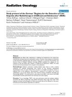
Figure 7: Waste composition o f Hanoi [2 0 ]................................................................ 15
Figure 8: Densified RDF (Saitama Prefectural Environmental Management
Center, Ja p a n )..................................................................................................................20
Figure 9: Schematic Representation o f MBT Process [8 | ...................................... 23
Figure 10: Herhof Stabilat method [11]........................................................................25
Figure 11: Schematic diagram o f MBT CD.08 [14].................................................. 28
Figure 12: Heat value o f RDF product - MBT CD.08method [ 14]........................29
Figure 13: RDF composition for 3 barrels....................................................................31
Figure 14: RDF sample preparing process.................................................................. 32
Figure 15: Waste barrel......... .......................................................................................... 33
Figure 16: Temperature in stabilization barrels.......................................................... 39
Figure 17: Composting temperature depending on C:N r a tio ................................. 40
Figure 18: Temperature differences in stabilization barrels..................................... 41
Figure 19: Leachate v o lu m e ...........................................................................................42
Figure 20: Water co n te n t................................................................................................ 43
Figure 21: Waste input composition (left) and estimated RDF output composition
(right) - (a) sample 1, (b) sample 2, (c) sample 3 ....................................................45
Figure 22: Gross heating value comparison with fossil fuel and RDF from
different studies............................................................................................................... 47
Figure 23: GHGs emission from RDF sample compare with fossil fuel (kg C 0 2.Cq
,'MJ) [ 9 ] .............................................................................................................................50
6
L ist o f figures/ tables
M aster Thesis
L i s t OF TABLES
Table 1: Waste composition in Hanoi in 1995 and 2003 [20]...................................15
Table 2: MSW eeneration and collection rate in cities/towns in Vietnam ............. 16
Table 3: Type o f refuse derived fuel........................................................................... 18
Fable 4: Typical RDF composition in some resions [8] .........................................20
Table 5: Quality o f RDF from household and industrial sources [8] .....................21
Table 6 : Quality o f RDF in some Europe Countries [17]..........................................22
Table 7: Conversion rate for RDF production according to treatment process and
country.............................................................................................................................. 26
Table 8: Annual RDF production from MSW in some countries [1]................... 27
Table 9: Waste input characteristics for RDF production (Đặng Ngọc Châu
experiment) [6] ............................................................................................................... 29
Table 10: Comparison RDF product quality [6, 14]...................................................30
Table 11: Waste input com position...............................................................................32
Table 12: Characteristics o f waste fraction (Vietnam based) [9 ].............................35
Table 13: GW P according to IPCC [18]....................................................................... 36
Table 14: Stabilization tim e.............................................................................................38
Table 15: Reduction o f waste fraction after composting [1 6]..................................44
Tabic 16: Heating value................................................................................................... 46
Table 17: C 0 2 emission from combustion process (kg/kg R D F)............................ 48
7
M a ster Thesis
Introduction
In t r o d u c t i o n
Vietnam is one o f the most rapidly developing countries in last decades. High
density o f population and quickly growing o f living standard as well as
consumerism give Vietnam more and more challenges. One o f them is the
growth o f energy demand in all sectors. Prices of electricity and gasoline - two
main energy sources in Vietnam - are constantly increasing in recent years.
Clean and renewable energy has become an interesting topic which draws much
attention from the society as well as the scientific community.
Another side-effect o f development which is also brought by consumerism and
high population is rapid increase o f solid waste generation. However, an efficient
solution
for
solid
waste
management
especially
municipal
solid
waste
management is still a challenge in Vietnam. One reason is that waste
management in Vietnam lacks separation at source.
To cope with those problems, energy from waste is being studied and considered
a solution. There are several ways for converting waste into energy which have
different requirement on technology and finance. One o f them is RDF production
by bio-stabilization method which is considered as a suitable way when
investment is limited and there is not waste separation at source.
There are several researches on this topic in Vietnam which showed possibility
o f implementation bio-stabilization as RDF production method in Vietnam.
Based on previous study, this research “Study the substitution of fossil fuels by
RDF produced from municipal solid waste of Hanoi” was carried out with the
following objectives:
•
Assessment of bio-stabilization process in RDF producing.
•
Study the influence o f waste composition on RDF quality.
•
Evaluation of Green House Gases (GHG) emission and other RDF quality
parameter to assess the possibility o f substitution RDF for fossil fuel.
8
M aster Thesis
1. Theoretical background
1. T h e o r e t i c a l b a c k g r o u n d
1.1.
Situation o f global energy consu m ption
/. /. 1.
Global energy consumption
In history, the world energy consumption is constantly increasing except some
periods when it slightly reduced mainly due to economic problem. In 2010,
global energy consumption rebounded strongly, driven by economic recovery.
The growth in energy consumption was broad-based, with mature OECD
economies joining non-OECD countries in growing at above-average rates. All
forms o f energy has grown strongly, with growth in fossil fuels in 2010
suggesting that global C 0 2 emissions from energy use grew at the fastest rate
since 1969. [1]
W orld c o n su m p tio n
Minor, tcmntt o»
130£K
9 Cod
9 RanawaMe*
1200C
■ Hytfroeiectriaty
* f'iuctov energy
■
1100C
N a tu ral g a s
■ Ol
10003
900C
7000
eox
5000
aooc
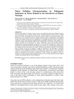
Figure 1: Global energy consumption from 1985 to 2010 (million tons of oil
equivalent) [1]
Figure 1 shows the trend o f energy consumption in the world. After falling for
two consecutive years, global oil consumption grew by 2.7 million barrels per
day (b/d), or 3.1%, to reach a record level o f 87.4 million b/d. This was the
largest percentage increase since 2004 but still the weakest global growth rate
among fossil fuels. World natural gas consumption grew by 7.4% - the most
9
M aster Thesis
1. Theoretical background
rapid increase since 1984. On the other hand, coal consumption also grew by
7.6% in 2010. Coal now accounts for 29.6% o f global energy consumption, up
from 25.6% 10 years ago.
Energy price developments were mixed. Oil prices remained in the $70-80 range
for much o f the year before rising in the fourth quarter. With the OPEC
production cuts implemented in 2008/09 still in place, average oil prices for the
year as a whole were the second-highest on record. (Figure 2) [1]
H Gasoline
■ Gas oil
■ Heavy fu el Oil
160
à
150
140
130
120
ñ
j
110
1
100
i
J
r
k
M
r
J
*
/
H
93
94
9S
/ J
V
v J
Ar
96
97
,y .
<Ì A
.
98
99
>
k - s -s s
00
ot
J\
J1
J
/
á A
ft
/
90
J
/
J
70
w
1
V
1 1
60
50
40
/
/
k -
80
30
20
10
02
03
04
os
06
07
OB 09
10
0
Figure 2: Rotterdam product oil prices - u s dollars per barrel [1]
According to 2011 Beyond Petroleum (BP) report, natural gas prices in 2010
grew strongly in the UK and in markets indexed to oil prices (including much o f
the world’s LNG); but prices remained weak in North America - where shale gas
production continued to increase - and in continental Europe (partly due to a
growing share o f spot-priced deliveries) (see Figure 3). Coal prices remained
weak in Japan and North America, but rose strongly in Europe due to coal
production grew robustly in the u s and Asia but fell in the European Union(EU).
In recent years, people have witnessed a rapid growth o f non-fossil energy.
Global hydroelectric and nuclear output each saw the strongest increases since
2004. Hydroelectric output grew by 5.3%, with China accounting for more than
60% o f global growth due to a combination o f new capacity and wet weather.
10
M a ste r Thesis
1. Theoretical background
Worldwide nuclear output grew by 2%, with three-quarters o f the increase
coming from OECD countries. French nuclear output rose by 4.4%, accounting
for the largest volumetric increase in the world. Other renewable energy sources
continued to grow rapidly. [ 1]
Figure 3: Natural gas price (dollars/Btu) [1|
Global biofuels production in 2010 grew by 13.8%, or 240,000 b/d, constituting
one o f the largest sources of liquids production growth in the world. Growth was
driven by the US (+140,000 b/d, or 17%) and Brazil (+50,000 b/d, or 11.5%).
Renewable energy used in power generation grew by 15.5%, driven by continued
robust growth in wind energy (+22.7%). The increase in wind energy in turn was
driven by China and the US, which together accounted for nearly 70% o f global
growth. These forms o f renewable energy accounted for 1.8% o f global energy
consumption, up from 0 .6% in 2000. [ 1]
1.1.2.
Change in share o f world prim ary energy
When looking at the share of world primary energy, oil, coal and natural gas are
three main sources o f energy. In the past 20 years, percentage o f oil in total
primary energy consumption is reduced rapidly. Energy crisis, high oil price and
environmental problems are making people looking for new sources o f energy
which is more sustainable. Hydro and nuclear energy are popular non-fossil
energy sources nowadays. However, both o f them showed their disadvantages.
11
M aster Thesis
1. Theoretical background
Especially after nuclear crisis in Japan, March 2011, people have to look for new
clean and safe energy.
C ontributions to gro w th
S hares o f w o rld p rim a ry en erg y
50%
0 i|
2.5 9i
■ R enew ables*
40%
2m
■ Hydro
H Nuclear
30%
■ Coal
20 %
1.0%
■ Gas
10%
0.59c
Hydro
M Oil
0 .0 %
1970-1990- 20101990 2010 2030
Includes biofuets
Figure 4: Shares of world primary energy |1]
BP predicted that world primary energy consumption grew by 45% over the past
20 years, and is likely to grow by 39% over the next 20 years. Global energy
consumption growth averages 1.7% p.a. from 2010 to 2030, with growth
decelerating gently beyond 2020.
Non-OECD energy consumption is 68% higher by 2030, averaging 2.6% p.a.
growth from 2010, and accounts for 93% o f global energy growth. OECD energy
consumption in 2030 is just 6% higher than today, with growth averaging 0.3%
p.a. to 2030. From 2020, OECD energy consumption per capita is on a declining
trend (-0 .2 % p.a.).
The fuel mix changes relatively slowly, due to long asset lifetimes, but gas and
non-fossil fuels gain share at the expense o f coal and oil. The fastest growing
fuels are renewables (including biofuels) which are expected to grow at 8.2% p.a.
2010-30; among fossil fuels, gas grows the fastest (2.1% p.a.). [1]
One o f renewables source o f energy is waste. Waste to energy is a hot topic in
many countries. It not only provides a non-fossil energy source but also solves
12
M a ster Thesis
1. Theoretical background
the problem o f waste management. Recovered energy from waste is used to
generate electricity and heat for household or industrial use. However, generating
quality fuel from waste and controlling environment impact during producing
process is still challenges for developing country such as Vietnam.
1.1.3.
Energy consumption in Vietnam
Vietnam is one o f the best performing economies in the world over the last
decade. Real GDP has on average grown by 7.3 percent per year during 19952005 and per capita income by 6.2 percent per year. In US dollar terms, income
per capita rose from $260 in 1995 to a 2007 level of $835 [2]. Electricity
consumption per capita increased rapidly since Vietnam changed to market
economy in 1990s. In only 18 years since 1990 to 2008, electricity consumption
per capita in Vietnam increased from 98 kWh to 810 kWh, nearly ten times
greater (see Figure 5).
"S
iB Vietnam
( USE.ELEC.KH.PC/countries/VN?displav=graph)
Figure 5: Electricity consumption in Vietnam (kWh per capita)
Moreover, Vietnam population is continuously increasing in the last decade
despite o f many government efforts. High population and improvement o f
standard living push more pressure on energy supply. Furthermore, the country’s
industrialization and integration into the global economy are others reason for
energy
consumption
growing
in Vietnam.
Primary
energy
consumption,
excluding biomass, grew at an annual rate o f 10.6% in the 2000-2005 periods.
Despite the fast growth, a large part of the rural population still relies heavily on
13
M aster Thesis
1. Theoretical background
non-commercial biomass energy sources, which still accounts for almost half of
total energy consumption (see Figure 6). Vietnam's per capita consumption o f
commercial energy thus remains among the lowest in Southeast Asia. Energy is
being used inefficiently, and energy production and distribution are poorly
managed.
Comb, renew & waste
42.0%
_
Coal/peat 19.9%
Hydro 3.8%
Gas 10.5%
Oil 23.8%
59,415 ktoe
(. org/'stats/pdf graphs/ VNTPESP I. pdf)
Figure 6: Share of total primary energy supply in Vietnam in 2008
Even though renewable and waste energy accounts for 42% in total primary
energy supply in Vietnam; waste used to generate energy is mainly agriculture
waste and its product is only used for domestic purpose. In industrial sector,
main energy source is still fossil fuel. There are several laboratory and pilot
researches about generating energy from waste for industrial purpose but it has
not been implemented in Vietnam. [6, 14]
1.2.
1.2.1.
M u n icip al solid w aste m a n a g e m en t in H anoi
Waste gen eration
Hanoi is the capital o f Vietnam and the country’s second largest city. Its
population in 2009 was estimated at 2.6 million for urban districts, 6.5 million
for the metropolitan jurisdiction [23]. Rapid economic growth coupled with fast
urbanization in the last decade has pushed solid waste management to the
forefront of environmental challenges. According to National Environmental
Report (2010), waste generation in Vietnam’s cities in 2008 was
1.45
kg/capita/day - 45% higher than in 2004 [21]. Hanoi and Ho Chi Minh city
14
1. Theoretical background
M aster Thesis
(HCMC) are the main waste generators with 8,000 ton/day (2.92 million ton/a),
accounted for 45.24% o f total urban Municipal Solid Waste (MSW); whereby
HCMC produces 5,500 tons/d and the left is generated by Hanoi (2006-2007)
[24].
■ Organic
■ Paper and textiles
B Plastic, rubber, leather, w
ood, hair, feathers
■ Metal
■ Glass
■ Inert matter
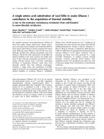
Figure 7: Waste composition o f Flanoi [20]
In most cities in Vietnam, MSW account for 60-70% o f total generated waste. In
some cities, the share o f MSW can reach 90%. In Hanoi, organic fraction is the
main part o f waste - 49%. The other half o f generated waste are plastic, paper,
textile, metal, glass, and inert matter (see Figure 7). [6]
Table 1: Waste composition in Hanoi in 1995 and 2003 [20]
Percent o f total
Waste component
1995
2003
51.9
49.1
Paper and textiles
4.2
1.9
Plastic, rubber, leather, wood, hair,
feathers
4.2
Metal
0.9
6.0
Glass
0.5
7.2
38.0
18.4
0.2
0.9
Organic
16.5
(Plastics 15.6)
Inert matter
Others
15
1. Theoretical background
M aster Thesis
Waste composition in Hanoi has changed during the last decade. Organic waste
percentage is reducing and plastic waste percentage is increasing. This is due to
the more affluent lifestyles, larger quantity o f commercial activities, and more
intense industrialization. These activities increase the proportion o f nondegradable waste (such as plastic, metal, and glass) found in urban waste.
Plastics, metal, glass increased from 4.3%, 0.9% and 0.5% in 1995 to 15.6%.
6.0% and 7.2% respectively in 2003. It is estimated that, the generation rate of
plastic increased about 18.3% p.a. Plastic which has high heating value is
expected to contribute to the potential o f producing RDF from MSW in Vietnam.
[20 ]
1.2.2.
Collection and treatment
MSW collection rates and efficiency vary from one area to the next depending
on the size o f the city, the distance to the urban center and the type o f collection
service. Hanoi, capital o f Vietnam, has the highest MSW collection rate - 98%.
MSW there is mainly collected by State-owner Public Urban Environment
Companies (URENCO) then transported to Nam Son landfill. Table 2 shows
waste generation and waste collection in some big cities o f Vietnam. [9]
Table 2: MSW generation and collection rate in cities/towns in Vietnam
No
Name o f
city/town
Generated
amount
m
Collected
amount
m
Collection
rate [%]
Reference
1
Hanoi
2,500
2,450
98.0%
URENCO Hanoi (2006)
2
Hai Phong
690
552
80.0%
Master plan on Hai Phong
(2005)
3
Hue
178
160
89.9%
local URENCO
4
Da Nang
647
541
83.6%
5
HCMC
5,128
4,102
80.0%
local URENCO
As for waste treatment, landfill is a dominant form o f solid waste disposal in
Vietnam currently. A survey with 90 URENCOs in Vietnam was taken by Kawai
et al. in November 2009 by questionnaire; 83 feedbacks o f environmental
16
1. Theoretical background
M a ster Thesis
companies which serve o f 21.9% population. The result showed that around 4%
o f collected MSW is composted: the rest is disposed at landfill-sites. [13]
In Hanoi, Cau Dien composting plant was established in 1992 under the
management o f Hanoi URENCOs dealing with municipal solid wastes, designed
capacity is 60 tons/d. In 2002. the plant was expanded and upgraded in capacity
to 140-150 tons/d. The compost products o f Cau Dien is trading on market and
the trading amount is increasing yearly, 2.114 tons in 2004: 2,735 tons in 2005;
2.799 tons in 2006 and 4,485 tons in 2007 [9].
Since 1997, waste incinerators were built in Vietnam; however this method is
only applied for healthcare waste due to its high expense. [9]
Reuse and recycling in Vietnam reach a high rate. Many households have a habit
o f separation recyclable waste then giving or selling it away. This is the reason
that metal, textile only account for 6% and 1.9% respectively in waste stream.
However, people are losing the custom due to economy develops and standard
living increases. Recyclable waste is then recycled mainly in small craft village
around city.
As for waste composition o f Hanoi, there is high percentage o f plastic and it is
still increasing. This kind o f waste contains high energy - heating value.
Therefore dumping plastic in landfill is not only the problem of non-degradable,
it also a waste o f resources. However, recovery energy from waste is still new
subject in Vietnam. There are several researches and pilot studies on this topic,
but it is still not implemented in reality. More detail o f recent researches and
studies will be given in the next part of this thesis.
1.3.
1.3.1.
R efuse-d erived fuel (R D F )
History
RDF or refuse derived fuel was developed due to high demand o f MSW
treatment. Date back to XIX century, many household in USA and Europe
burned their waste in open-burning. The first systematic cremation o f waste at
municipal level was built in Nottingham, England in 1874. However heat from
incinerator is first used to generate power in 1876 in Leeds, England. Then, in
1885, a garbage furnace was established in United
17
M aster Thesis
1. Theoretical background
waste plant was built in Hamburg with 35 cells o f multitubular boilers and forced
draft fans. [4]
By 1917. there was the first method which converting waste into combustible
bricks, it is likely to be the first day o f processing activities to produce RDF
which has had many improvement in the next decades. However, the term
'"refuse derived fuel” (RDF) had not been given until 1973 (Dr. Jerome Collins)
[4]. In fact. RDF is a category o f the generic class of Waste-Derived Fuel (WDF)
which include wood waste, hogged waste paper, and or so. From residues, there
are some other types o f "'Derived Fuels” such as Recovered Fuel (REF),
Packaging Derived Fuel (PDF). Paper and Plastic Fraction (PPF) and Processed
Engineered Fuel (PEF) which are taken from source-separated waste [8J.
Although having a long history. RDF has not been given the universe definition.
In fact, it depends on the technologies, methods o f each sectors, each countries.
European Commission Directorate General Environment defines: “RefuseDerived Fuel covers a wide range o f waste materials which have been
processed to fu lfill guideline, regulatory or industry specifications m ainly to
achieve a high calorific value. Waste derived fu els include residues fro m M SW
recycling, industrial/trade waste, sewage sludge, industrial hazardous waste,
biomass waste, etc.” [8]The American Society for Testing and Materials
(ASTM) has defined several forms o f RDF, as shown in Table 3. [4]
Table 3: Type of refuse derived fuel
ASTM
Description
Designation
RDF-1
Waste used as fuel in as-discarded form
RDF-2
Wastes processed to coarse particle size with or without magnetic
metals
RDF-3
Shredded fuel derived from MSW has been processed to removed
metal, glass, and other inorganic materials (this material has a particle
size such that 95 wt.% passes through a 50 mm square mesh)
RDF-4
Combustible waste processed into powder form: 95 wt.% passing 10
mesh screen (2 mm)
RDF-5
Combustible waste densified (compressed)
cubettes, or briquettes (this is d-RDF)
18
into
pellets,
slugs,
M aster Thesis
1. Theoretical background
RDF-6
Combustible waste processed into liquid fuel
RDF-7
Combustible waste processed into gas fuel
RDF-1 in Table 3 refers to MSW as fuel in the as-received or as-discarded
condition. Worldwide. RDF-1 is the major form o f RDF used. Another term for
RDF-5 is densified refuse derived fuel (d-RDF). This was chosen as a generic
class to include pellets, briquettes, cubettes and the like by Alter in 1975 in a
proposal to the U.S. Environmental Protection Agency. [4]
One important term in RDF's definitions is "high calorific value". This is to be
one of the important parameters considered during RDF production, which is
given more detail in the follow ing sections.
1.3.2.
Characteristics
As for A STM 's types o f RDF, waste can be processed to make fuel in solid,
liquid or gas phase. In the content o f this thesis, only solid RDF will be
concentrated and it will be mentioned as RDF from here. RDF can be produced
under the fluff or densified forms. As regards Huff RDF, it is not biologically
stable and difficult to store, therefore, it must be used within 2 or 3 days. This
kind o f RDF has low bulk density, resulting in the limited market and in
demanding the proper design o f combustion systems.
In terms o f densified or pelletized RDF (Figure 8), it has advantages over fluff
type. It is transportable and easier to handle and store. If kept under right
condition, densified RDF can be stored indefinitely. This kind is also suitable for
burning on wider range o f combustion systems. However, due to the well
preparation, it is also cost more than fluff RDF. Therefore, one factor should be
care about when choosing between fluff RDF and pelletized RDF is the distance
between RDF producing facility and combustion place.[5]
19
M aster Thesis
1. Theoretical background
Figure 8: Densified RDF (Saitama Prefectural Environmental Management
Center, Japan)
One characteristic o f MSW is heterogeneous; therefore RDFs produced from
MSW has different composition. Normally, RDF contains plastic (exclude
recyclable plastic), paper, cardboard and textile; however proportion o f them
changes depending on time, location and management system. Table 4 shows
RDF composition from various sources. This difference can result in RDF
quality especially heating value characteristic. In table 4, it can be seen that the
main composition in western and eastern countries is different. The distinction in
paper and cardboard can be a good example. In Italy and UK, the percentage of
paper and cardboard is respectively 5 times and 10 times higher than it in Taiwan.
Table 4: Typical RDF composition in some regions |8]
Waste fraction
Plastic
Flemish Region[4]
ltaly(4)
UK(4)
Taiwan(10)
Sorting
process
(%)
MBT
(%)
(%)
(%)
25-100
mm (%)
>100 mm
(%)
31
9
23
11
29.15
57.81
20
1. Theoretical background
M aster Thesis
Paper/cardboard
13
64
44
84
8.08
5.7
Textile
14
27(a)
12
5(0
7.43
18.23
Others
(undesirable
materials, wood.
Le ath er...)
42
55.34(d)
18.26(d)
Notes:
a) Including
rubber,
21
synthetic
material;
b) Organic
degradable
waste;
c) Including glass, wood, textile, and metals; d) Including garden trimmings, leather,
rubber, metals.
RDF quality can be roughly evaluated by calorific value, ash content, water
content (WC) and chlorine, sulfur content. Quality o f RDF produced from
several kinds o f waste is shown in table 5. In this table, it can be seen that RDF
from industrial waste has lower water content and higher heating value than
household or commercial waste. It is due to low percentage o f organic waste in
industrial w'aste.
Table 5: Quality of RDF from household and industrial sources |8|
Sulfur
content
(% wt)
Water
content
(% w t)
RDF source
Calorific
value
(MJ/kg)
Ash
residue
(% wt)
Chlorine
content
(% wt)
Household waste1’
12-16
15-20
0.5-1
Household waste2’
13-16
5 -1 0
0 .3 -1
0.1 -0 .2
25 -35
Commercial waste2’
16-20
5-7
< 0.1-02
<0.1
10-20
RDF from industrial waste1’
18-21
10-15
0.2-1
Demolition waste2’
14-15
1-5
<0.1
10-35
3-10
<0.1
15-25
1) RDC and Kema 1999
2) Data reported for Finland
Obviously, heat value has the decisive role in the way that RDF used. In
comparison with fossil fuel, heating value o f RDF from table 5 is lower than
liquid fossil fuel (> 20 MJ/kg) and similar with heating value o f wood and coal
(15-37 MJ/kg). Another important characteristic o f RDF is Chlorine content.
High Chlorine content will lead to damaging o f combustion system. More
21
M aster Thesis
1. Theoretical background
seriously, high concentrate of Chlorine increase the risk of Dioxins and Furans
formation. Heavy metal concentration is also considered when burning RDF.
fable 6 lists RDF standard which is required by law in some European country.
Table 6: Quality of RDF in some Europe Countries (17|
Parameters
Switzerland
mg/MJ
Finland mg/MJ
Italy mg/MJ
Germany mg/MJ
As
0.6
n.a
0.5
0.7
Be
0.2
n.a
n.a
0.1
Cd
0.1
0.3
0.4
0.5
Co
0.8
n.a
n.a
0.7
Cr
4.0
n.a
6
14
Cu
4
n.a
17
56
Hg
0.02
0.03
n.a
0.07
Ni
4
n.a
2
8.9
Pb
8
n.a
11
n.a
Sb
0.2
n.a
n.a
3.3
Se
0.2
n.a
n.a
0.3
Sn
0.4
n.a
n.a
3.9
Te
n.a
n.a
n.a
0.3
Tl
0.12
n.a
n.a
0.11
V
4
n.a
n.a
1.4
Zn
16
n.a
28
n.a
Chlorine
n.a
1.5% by
weight
0.9% by weight
Only declaration
1.3.3.
Producing methods
RDF can be produced from different types o f waste: MSW. industrial waste, and
commercial waste. In this thesis, RDF which produced from MSW will be
concentrated. In general. RDF producing is a process in which high-caloric
material will be taken out from waste stream to produce fuel in type o f gas,
liquid or solid. RDF producing methods can be divided to two main groups:
•
Mechanical Biological Treatment (MBT) which can be divided to aerobic
or anaerobic-MBT.
22
1. Theoretical background
M aster Thesis
•
Dry Stabilization Process (DSP). In this method waste can be stabilized
by biological process or physical process.
The main difference between these two methods is that in MBT method, mixed
waste is separated to organic, recyclable, metal, inert, and high-caloric waste,
and then each fraction will be treated or reused in different ways; Only highcaloric waste will be used for RDF production. However, in DSP method, mixed
waste is Firstly digested in digested drum or physically dried to reduce waste
volume and water content as well as to stabilize microorganism activities before
separation step.
Mechanical Biological Process
RESIDUAL MUNICIPAL SOLID WASTE
c
0
<0
V*
3.
0)
CO
?.ỹ
5ằ P* Đ
(5 ô o
40 i? S»
s o t
—*
u d)
0) £
■2
.2 2
cq k
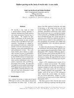
Figure 9: Schematic Representation of MBT Process [8]
23
M aster Thesis
1. Theoretical background
The first step o f this method is separation. Waste is separated by different
methods to divide in to organic, inert, recyclables and RDF fraction (see Figure
9). Inert material, in this case including metal, will be recycled. Organic matter
will become input material for compost facility. RDF fractions here means the
high-calorific matter such as plastic, nylon, paper or textile which can not be
recycle due to contaminated or mixed with PVC. In some process, recyclable
plastic is not separated to recycle; it is considered an RDF fraction in this case.
Therefore, MBT process can attain 3 main purposes: material recovery, nutrient
recovery and energy recovery. In order to gain such three products, the
separation step can be considered as the most important process. There are
various ways to separate waste, some main stages including four main steps:
magnetic separation, shredding, air classifying and finally screening.
RDF fractions from separation process can be combusted directly or processed to
make higher quality RDF. In most processes, RDF fraction is shredded and dried
to meet RDF quality standard before go to market.
Dry Stabilization Process
DSP can be done in several ways. The main point o f this method is that mixed
waste will firstly be dried to reduce volume, water content and stabilize
microorganism activities. In this method, organic waste is not separated to
recovery. It is only used to make composting condition in case o f biological
stabilization. Three main steps o f DSP are shredding, drying which can be
physical (using heat), or biological process, inert and metal separation. Figure 10
shows DSP method o f a Germany company Herhof GmbFI.
•
Shredding: this step aim to reduce waste size which is more suitable for
next step, and also well mix the waste to make same condition.
•
Drying: this step can be done in two ways. Mixed waste can be dried
using provided heat (physical process). This method can obtain stable
product quality in short time; however, it is costly due to energy requiring.
In Herhof Stabilat method, biological process is used for drying step.
Waste after going through shredding step is kept in stabilization tank in 67 days. Here, microorganisms degrade organic material in aerobic
condition generating heat. The temperature in stabilization tank can reach
24
M aster Thesis
1. Theoretical background
60-70°C depending on waste amount and air circulation. This can be
considered clean method because it does not require energy providing.
Evaporation
Exhaust air
Biological drying
I Mixed Stabilaf | approx. 70*
Fractionation
Metal separation
Density separation^»-------- Light material
approx. b0%
Calorific value.
KU/t
O f / U p
Stabilat*
approx. 2%
< ^Density s e p a r a tio n ^ - ^
Light material/Pust]-----r x
Metal separation
/T y
rv A
Energy or
material
separation
X-jy/ !
1ft™
Road construction
Industrial,
Power plants
Figure 10: Herhof Stabilat method [11J
25
i
Biofuels
Methanol/Diesel
M a ster Thesis
1. Theoretical background
Inert and metal separation: inert and metal (non-combustible fraction)
•
is separated from waste. Waste now containing mainly high calorific
fractions can be pelletized to storing.
Adv antage o f DSP is that it can be applied directly for wet and mixed waste,
especially when waste separation at source is not applied and central separation
need high investment.
Additives for RDF
During the production o f RDF, some additives have been used for fix chlorine or
to modify properties o f RDF. For example, Mg(OH)2 has been used for
minimizing slag formation. Besides, M g(OH)2 and CaO has been used for
explore chlorine retention and the effect on clinker formation. [ 12]
1.3.4.
R D F production and utilization / 8/
The quantity o f RDF produced per ton o f MSW varies depending on the type o f
collection, treatment process and quality requirement. Information collected by
European Commission - Directorate General Environment indicated that the rate
o f RDF production from MSW can vary between 23 and 50% by weight o f waste
processed depending on the treatment process used and country (Table 7)
Table 7: Conversion rate for RDF production according to treatment
process and country
Country
Treatment type
Rate (%)
Austria
MBT
23
Belgium
MBT
40-50
Finland
MT
Variable
Netherlands
MT
35
United Kingdom
MT
22-50
Notes: MBT Mechanical biological treatment
26
MT Mechanical treatment
M aster Thesis
1. Theoretical background
The total quantities of RDF produced from MSW in the European Union have
been estimated to amount to about 3 million tons. Countries where RDF
production is already well established are Austria, Finland, Germany, Italy, the
Netherlands and Sweden. Countries where RDF production is currently being
developed are Belgium and the United Kingdom. RDF from MSW was produced
in the past in Denmark and France but this has been discontinued for economical
reasons. Amount o f RDF produced from MSW in some countries is shown in
table 8 .
Table 8: Annual RDF production from MSW in some countries j l|
Country
Amount o f RDF produced from MSW (103 t/a)
Austria
70
Finland
40-90
Germany
330
Netherlands
700
United Kingdom
90
Korea
635
Chile
400
The following options for the utilization and conversion of RDF from MSW to
energy have been used or could be used in the future:
•
on-site in an integrated thermal conversion device, which could include
grate or fluidized bed combustion, gasification or pyrolysis;
•
off-site at a remote facility employing grate or fluidized bed combustion,
gasification or pyrolysis;
•
co-combustion in coal fired boilers;
•
co-incineration in cement kilns;
•
co-gasification with coal or biomass.
1.3.5.
Researches in Vietnam
RDF production is attracting more and more concerns from scientist and
engineer in Vietnam. There are several RDF project was carried out in Son Tay,
27