Phase Control IC
Bạn đang xem bản rút gọn của tài liệu. Xem và tải ngay bản đầy đủ của tài liệu tại đây (454.65 KB, 16 trang )
Semiconductor Group 1
TCA 785
This phase control IC is intended to control thyristors, triacs, and transistors. The trigger pulses
can be shifted within a phase angle between 0 ˚ and 180 ˚. Typical applications include
converter circuits, AC controllers and three-phase current controllers.
This IC replaces the previous types TCA 780 and TCA 780 D.
(top view)
Pin Configuration
Phase Control IC TCA 785
Bipolar IC
Features
●
Reliable recognition of zero passage
●
Large application scope
●
May be used as zero point switch
●
LSL compatible
●
Three-phase operation possible (3 ICs)
●
Output current 250 mA
●
Large ramp current range
●
Wide temperature range
P-DIP-16-1
Type Ordering Code Package
TCA 785 Q67000-A2321 P-DIP-16-1
Pin Symbol Function
1 GND Ground
2
3
4
Q2
Q U
Q2
Output 2 inverted
Output U
Output 1 inverted
5 V
SYNC
Synchronous voltage
6
7
I
Q Z
Inhibit
Output Z
8 V
REF
Stabilized voltage
9
10
R
9
C
10
Ramp resistance
Ramp capacitance
11 V
11
Control voltage
12 C
12
Pulse extension
13 L Long pulse
14
15
Q 1
Q 2
Output 1
Output 2
16 V
S
Supply voltage
Pin Definitions and Functions
09.94
Semiconductor Group 2
TCA 785
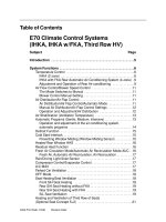
Functional Description
The synchronization signal is obtained via a high-ohmic resistance from the line voltage
(voltage V
5
). A zero voltage detector evaluates the zero passages and transfers them to the
synchronization register.
This synchronization register controls a ramp generator, the capacitor C
10
of which is charged
by a constant current (determined by R
9
). If the ramp voltage V
10
exceeds the control voltage
V
11
(triggering angle
ϕ
), a signal is processed to the logic. Dependent on the magnitude of the
control voltage V
11
, the triggering angle
ϕ
can be shifted within a phase angle of 0˚ to 180˚.
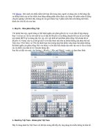
For every half wave, a positive pulse of approx. 30
µ
s duration appears at the outputs Q 1 and
Q 2. The pulse duration can be prolonged up to 180˚ via a capacitor C
12
. If pin 12 is connected
to ground, pulses with a duration between
ϕ
and 180˚ will result.
Outputs and supply the inverse signals of Q 1 and Q 2.
A signal of
ϕ
+180˚ which can be used for controlling an external logic,is available at pin 3.
A signal whichcorresponds to theNOR link of Q 1 and Q 2 is available at output Q Z(pin 7).
The inhibit input can be used to disable outputs Q1, Q2 and , .
Pin 13 can be used to extend the outputs and to full pulse length (180˚ –
ϕ
).
Q 1 Q 2
Q 1 Q 2
Q 1 Q 2
Block Diagram
Semiconductor Group 3
TCA 785
Pulse Diagram
Semiconductor Group 4
TCA 785
UnitParameter Symbol
min. max.
Limit Values
Absolute Maximum Ratings
VSupply voltage V
S
– 0.5 18
mAOutput current at pin 14, 15 I
Q
– 10 400
K/W
Thermal resistance
system - air R
th SA
80
V
V
V
Inhibit voltage
Control voltage
Voltage short-pulse circuit
V
6
V
11
V
13
– 0.5
– 0.5
– 0.5
V
S
V
S
V
S
µ
ASynchronization input current V
5
– 200
±
200
VOutput voltage at pin 14, 15 V
Q
V
S
mAOutput current at pin 2, 3, 4, 7 I
Q
10
VOutput voltage at pin 2, 3, 4, 7 V
Q
V
S
˚C
˚C
Junction temperature
Storage temperature
T
j
T
stg
– 55
150
125
Operating Range
VSupply voltage V
S
818
HzOperating frequency f 10 500
˚CAmbient temperature T
A
– 25 85
Characteristics
8
≤
V
S
≤
18 V; – 25 ˚C
≤
T
A
≤
85 ˚C; f = 50 Hz
UnitParameter Symbol
min. max.
Limit Values Test
Circuit
typ.
mASupply current consumption
S1 … S6 open
V
11
= 0 V
C
10
= 47 nF; R
9
= 100 k
Ω
I
S
4.5 16.5 10
µ
A
mV
Synchronization pin 5
Input current
R
2
varied
Offset voltage
I
5 rms
∆
V
5
30 1
430
200
75
V
k
Ω
Control input pin 11
Control voltage range
Input resistance
V
11
R
11
0.2 1
515
V
10 peak
Semiconductor Group 5
TCA 785
Characteristics (cont’d)
8
≤
V
S
≤
18 V; – 25 ˚C
≤
T
A
≤
85 ˚C; f = 50 Hz
UnitParameter Symbol
min. max.
Limit Values Test
Circuit
typ.
µ
A
V
mV
k
Ω
µ
s
Ramp generator
Charge current
Max. ramp voltage
Saturation voltage at capacitor
Ramp resistance
Sawtooth return time
I
10
V
10
V
10
R
9
t
f
10
100
3
1
1.6
1
1
225
80
1000
V
2
– 2
350
300
V
V
µ
s
µ
A
µ
A
Inhibit pin 6
switch-over of pin 7
Outputs disabled
Outputs enabled
Signal transition time
Input current
V
6
= 8 V
Input current
V
6
= 1.7 V
V
6 L
V
6 H
t
r
I
6 H
– I
6L
4
1
80
1
1
1
1
1
3.3
3.3
500
150
2.5
5
800
200
V
V
µ
A
µ
A
Long pulse switch-over
pin 13
switch-over of S8
Short pulse at output
Long pulse at output
Input current
V
13
= 8 V
Input current
V
13
= 1.7 V
V
13 H
V
13 L
I
13 H
– I
13 L
3.5
45
1
1
1
1
2.5
2.5
65
2
10
100
%
%
%
Deviation of I
10
R
9
= const.
V
S
= 12 V; C
10
= 47 nF
Deviation of I
10
R
9
= const.
V
S
= 8 V to 18 V
Deviation of the ramp voltage
between 2 following
half-waves, V
S
= const.
I
10
I
10
∆
V
10 max
– 5
– 20
1
1
±
1
5
20
µ
A
V
Outputs pin 2, 3, 4, 7
Reverse current
V
Q
= V
S
Saturation voltage
I
Q
= 2 mA
I
CEO
V
sat
0.1
2.6
2.60.4
10
2
Semiconductor Group 6
TCA 785
Characteristics (cont’d)
8
≤
V
S
≤
18 V; – 25 ˚C
≤
T
A
≤
85 ˚C; f = 50 Hz
UnitParameter Symbol
min. max.
Limit Values Test
Circuit
typ.
V
V
µ
s
µ
s/
nF
Outputs pin 14, 15
H-output voltage
– I
Q
= 250 mA
L-output voltage
I
Q
= 2 mA
Pulse width (short pulse)
S9 open
Pulse width (short pulse)
with C
12
V
14/15 H
V
14/15 L
t
p
t
p
V
S
– 3
0.3
20
530
3.6
2.6
1
1
V
S
– 2.5
0.8
30
620
V
S
– 1.0
2
40
760
V
1/K
Internal voltage control
Reference voltage
Parallel connection of
10 ICs possible
TC of reference voltage
V
REF
α
REF
2.8 1
1
3.1
2
×
10
– 4
3.4
5
×
10
– 4