Tính toán và thiết kế máy ép dầu trục vít (bản tiếng anh)_2006
Bạn đang xem bản rút gọn của tài liệu. Xem và tải ngay bản đầy đủ của tài liệu tại đây (2.69 MB, 129 trang )
PRELIMINARY DESIGN AND CONSTRUCTION OF A PROTOTYPE
CANOLA SEED OIL EXTRACTION MACHINE
A THESIS SUBMITTED TO
THE GRADUATE SCHOOL OF NATURAL AND APPLIED SCIENCES
OF
MIDDLE EAST TECHNICAL UNIVERSITY
BY
PELİN SARI
IN PARTIAL FULFILLMENT OF THE REQUIREMENTS
FOR
THE DEGREE OF MASTER OF SCIENCE
IN
MECHANICAL ENGINEERING
JUNE 2006
Approval of the Graduate School of Natural and Applied Sciences
__________________________
Prof. Dr. Canan ÖZGEN
Director
I certify that this thesis satisfies all the requirements as a thesis for the degree of
Master of Science
___________________________
Prof. Dr. Kemal İDER
Head of the Department
This is to certify that we have read this thesis and that in our opinion it is fully
adequate, in scope and quality, as a thesis for the degree of Master of Science
___________________________
Prof. Dr. Mustafa İlhan GÖKLER
Supervisor
Examining Committee Members:
Prof. Dr. Metin AKKÖK (METU, ME)
_________________
Prof. Dr. Mustafa İlhan GÖKLER (METU, ME)
_________________
Prof. Dr. Kemal İder (METU, ME)
_________________
Prof. Dr. Ali GÖKMEN (METU, CHEM)
_________________
Prof. Dr. İnci GÖKMEN (METU, CHEM)
_________________
I hereby declare that all information in this document has been obtained
and presented in accordance with academic rules and ethical conduct. I also
declare that, as required by these rules and conduct, I have fully cited and
referenced all material and results that are not original to this work.
Pelin SARI
iii
ABSTRACT
PRELIMINARY DESIGN AND CONSTRUCTION OF A PROTOTYPE
CANOLA SEED OIL EXTRACTION MACHINE
SARI, Pelin
M.Sc., Department of Mechanical Engineering
Supervisor: Prof. Dr. Mustafa İlhan GÖKLER
June 2006, 109 Pages
Growing energy demand in the world force people to investigate alternative
energy sources. Unlike coal or other fossil fuels, renewable energy sources are
promising for the future. Especially, seed oils are effectively used as energy
sources such as fuel for diesel engines. The scope of this study is to develop an
oil extraction machine specific to canola seed.
In this study, seed oil extraction methods have been investigated and various
alternatives for the extraction machine have been considered. For continuous
operation, oil extraction with a screw press is evaluated as the most appropriate
solution. Four different prototypes have been designed and manufactured.
According to the results of testing of prototypes, they have been modified and
gradually improved to increase oil extraction efficiency. The working principle
of the selected screw press based on the rotation of a tapered screw shaft
mounted inside a grooved vessel. The screw shaft is a single square-threaded
power screw having an increasing root diameter from inlet to exit while the
outside diameter of the screw shaft is 66 mm. Seeds are taken into the system at
iv
the point where the depth of the screw thread is maximum. Then they are pushed
forward by the threads on the rotating screw shaft and pass through inside the
vessel. So, the fed seeds are compressed as they move to the other side of the
vessel. Recovered oil escapes from high pressure zone and drains back. The oil
is drained out from the oil drainage holes that are machined on high pressure
zone of the vessel. Besides, the cake is extruded at the end of the vessel and the
screw shaft. The cake thickness is adjustable by the axial movement of the
screw shaft. By adjusting the cake thickness, different pressures can be obtained.
During the experiments, it is observed that four main features affect the oil
recovery rate. These are the geometry of the grooves inside the vessel, the taper
angle of the screw shaft, the operating temperature and the rotational speed.
With the final prototype, an oil recovery efficiency of 62.5% has been achieved
at 40 rpm with 15 kg/h seed capacity. Since the oil content of the seed is taken
as 40%, oil recovery rate of the developed oil extraction machine is 3.75 kg/h.
This efficiency is determined for a 0.8 mm cake thickness at 1.1 kW motor
power.
Keywords: Canola, Seed Oil, Screw Press, Oil Extraction
v
ÖZ
KANOLA TOHUM YAĞI ÇIKARMA MAKİNASININ PROTOTİPİNİN ÖN
TASARIMI VE ÜRETİMİ
SARI, Pelin
Yüksek Lisans, Makina Mühendisliği Bưlümü
Tez neticisi: Prof. Dr. Mustafa İlhan GƯKLER
Haziran 2006, 109 Sayfa
Dünyada gitgide büyüyen enerji ihtiyacı, insanları alternatif enerji kaynakları
bulmaya yönlendirmektedir. Bu şartlar altında, kömür ve fosil yakıtlarından
farklı olarak yenilenebilir enerji kaynakları gelecek vadetmektedir. Özellikle
bunlardan tohum yağı dizel motorlarda yakıt olarak kullanılmaktadır. Bu tezin
amacı, kolza bitkisine özel bir tohum ya ỗkartma makinas gelitirmektir.
Bu ỗalmada, ya ỗkartma metodlar aratrlm ve çeşitli alternatifler
geliştirilmiştir. Değerlendirilen bu alternatiflerin içinden sonsuz vidalı pres
seçilmiştir. Dört ayr prototip ỹretilmitir. Bu prototiplerle yaplan testlerin
sonucuna
gửre,
prototiplerde
deiiklikler
yaplm
ve
gelitirilmitir.
Gelitirilen ya ỗkartma makinasnn çalışma prensibi iç yüzeyi oluklu
silindirik bir haznenin içine yerleştirilmiş konik bir sonsuz vidalı şaftın
dönmesine dayanır. Sonsuz vidanın dişleri kare profilli ve tek sarmdan oluup,
iỗ ỗap giderek artarken d ỗap 66 mm’de sabittir. Tohumlar sonsuz vidalı
şaftın diş derinliğinin en derin olduğu yerden alınırlar. Sonra silindirik haznenin
vi
iỗinde dửnen afttaki diler sayesinde ileriye doru itilirler. Tohumlar ileri doru
ilerlerken skrlar. Ezilen tohumdan ỗkan ya, yỹksek basnỗ alanndan geriye
doru kaỗar. Ya, silindirik haznenin ỹzerine aỗlm ya deliklerinden dar
ỗkar. Bunun yanısıra, posa da silindirik haznenin ve sonsuz vidalı şaftın son
kısmında bulunan konik yỹzeyler arasndan ỗkar. Posa kalnl ayarlanabilirdir.
ầk genilii ayarlanarak, iỗeride farkl basnỗlar yaratlabilir.
Denemeler srasnda, ỗkan ya miktarn etkileyen dửrt ana faktửr saptanmtr.
Bunlar, silindirik haznenin iỗine aỗlan oluklar, sonsuz vidann konik yapısı,
sıcaklık ve dönme hızıdır. Geliştirilen makinayla 15 kg/saat tohum işleme
kapasitesine ulaşılmıştır. Ayrıca 40 rpm hızındayken, %62.5’luk bir verim elde
edilmiştir. Tohumun ya oran 40% olarak varsaylmtr. Bu varsayma gửre
ỗkarlan ya miktarı 3.75 kg/saat olarak hesaplanmıştır. Bu verim, system 0.8
mm kalınlığında posa ỗkarmaya ayarlanmken elde edilmitir. Denemeler
srasnda motorun bu verimlilikte harcad gỹỗ miktar 1.1 kW olarak
ửlỗỹlmỹtỹr.
Anahtar Sửzcỹkler: Kolza, Tohum Ya, Sonsuz Vidalı Pres, Yağ Çıkartma
vii
To My Family,
viii
ACKNOWLEDGEMENTS
I express sincere appreciation to Prof. Dr. Mustafa İlhan Gökler for his
guidance, advice, criticism, systematic supervision, encouragements, and insight
throughout the study. I also express my deep gratitude to Prof. Dr. Ali Gökmen
and Prof. Dr. İnci Gökmen for their great help and effort during this thesis study.
I wish to thank to Halit Şahin specifically for his willingness to help me
for all the times I ask for. Also I also thank to Arzu ệztỹrk, Halime Kỹỗỹk and
Filiz Gỹngửr for giving me support everyday.
I also would like to thank to METU-BİLTİR Research & Application
Center for the facilities provided for my work.
Special thanks go to my colleagues, Evren Ank, ệmer Kửktỹrk, Sevgi
Saraỗ, Mehmet Maat, Atayıl Koyuncu, Emine Ünlü, Kazım Arda Çelik, Arda
Ưzgen, Cihat Ưzcan, Hüseyin Öztürk, Özgür Cavbozar, İlker Durukan and
Derya Akkuş, for their valuable support and aid; to my senior colleagues Özkan
İlkgün, Ender Cengiz and Barış Civelek for their support and guidance.
I also want to thank my beloved family, Hesna Sarı, Göksel Sarı, Semin
Sar and Volkan Genỗ for their encouragement and faith in me.
I also appreciate UNDP, Anismak, FNSS, Mert Oymak, Nüket Kol,
Emre Özkan, Meltem Yıldız and Tulu Ertem for their support.
ix
TABLE OF CONTENTS
PLAGIARISM............................................................................................. iii
ABSTRACT................................................................................................ iv
ÖZ ………………………………………………………………………………..vi
ACKNOWLEDGEMENTS.......................................................................... ix
TABLE OF CONTENTS..............................................................................x
CHAPTER
1. INTRODUCTION..................................................................................1
1.1 Renewable Energy.................................................................................... 1
1.2 Biomass Energy Potential in Turkey........................................................ 5
1.3 Balaban Valley Project ............................................................................. 5
1.4 Canola....................................................................................................... 7
1.5 Canola Oil Recovery Process ................................................................... 8
1.6 Scope of the Thesis................................................................................. 10
2. LITERATURE SURVEY ON SEED OIL EXTRACTION .....................11
2.1 Fundamentals of Fluid Property for the Compressed Seed .................... 11
2.2 Previous Studies for Different Screw Configurations used in Screw
Presses ....................................................................................................... 16
2.3 Some Typical Seed Oil Extraction Machines......................................... 17
2.3.1 Komet Oil Presses ......................................................................... 17
2.3.2 Rosedowns Oil Presses.................................................................. 18
2.3.3 Vincent Screw Presses................................................................... 20
2.3.4 Strainer Type Screw Presses ......................................................... 21
2.4 Available Patents for Screw Presses ...................................................... 21
2.4.1 Continuous screw press with strainer cage recovering oils under
controlled back pressure (1998) (Pub. Num.: DE19715357) ........ 21
x
2.4.2 Screw press having a plurality of throttle points and at least one
cam movable transversely thereto (1994) (Pub. Num.:
US5341730)................................................................................... 22
2.4.3 Screw press for extracting oil from seeds etc. - has cylinder
composed of rings in or between which are passages which can
quickly and easily be connected to cooling fluid supply (1992)
(Pub. Num.: DE4109229) .............................................................. 23
3. CONCEPTUAL DESIGNS FOR OIL EXTRACTION MACHINES ......25
3.1 Comparison between Oil Extraction Methods ....................................... 25
3.2 Comparison between Screw Shaft Configurations................................. 28
3.2.1 Straight Screw Shaft...................................................................... 28
3.2.2 Screw with Tapered Shaft ............................................................. 29
3.2.3 Screw with Variable Pitch............................................................. 29
3.2.4 Screw with Tapered Shaft and Variable Pitch............................... 30
3.2.5 Screw with Reverse Worm............................................................ 31
3.3 Comparison of the Choke Mechanisms for Cake Drainage ................... 32
3.3.1 Nozzle Type Choke Mechanism ................................................... 32
3.3.2 Conical Type of Choke Mechanism .............................................. 33
3.4 Comparison of Oil Drainage Systems .................................................... 34
3.4.1 Drilled Holes ................................................................................. 34
3.4.2 Lining Bars with Spacers .............................................................. 34
3.4.3 Fiber Filter Sleeves........................................................................ 35
3.4.4 Barrel Rings................................................................................... 35
3.5 Conceptual Designs for the Canola Seed Oil Extraction Machine ........ 36
4. PRELIMINARY AND DETAILED DESIGN OF THE OIL
EXTRACTION MACHINE .................................................................43
4.1 Preliminary Design................................................................................. 43
4.1.1 Design Tree ................................................................................... 43
4.1.2 Skeleton ......................................................................................... 45
4.1.3 Hopper ........................................................................................... 45
4.1.4 Main Body..................................................................................... 46
4.1.4.1 Screw Shaft........................................................................... 46
xi
4.1.4.2 Vessel ................................................................................... 47
4.1.4.3 Flange ................................................................................... 48
4.2 Detail Design Calculations..................................................................... 49
4.2.1 Design Specifications .................................................................... 49
4.2.2 Important Design Inputs................................................................ 50
4.2.2.1 Required Oil Recovery Rate................................................. 51
4.2.2.2 Maximum Available Power.................................................. 54
4.2.3 Design Calculations for the Prototype........................................... 54
4.2.3.1 Screw Shaft Design .............................................................. 55
4.2.3.2 Vessel Design ....................................................................... 61
4.2.3.2.1 Oil Drainage Zone ....................................................... 61
4.2.3.2.2 Groove Profile Selection for the Inside Vessel ........... 65
5. MANUFACTURING AND TESTING OF PROTOTYPE OIL
EXTRACTION MACHINES...............................................................68
5.1 First Prototype ........................................................................................ 68
5.2 Second Prototype.................................................................................... 69
5.3 Third Prototype....................................................................................... 72
5.4 Fourth Prototype..................................................................................... 78
6. DISCUSSION AND CONCLUSION ...................................................87
6.1 Discussion on Manufacturing and Assembly Stage of the Prototypes... 87
6.2 Discussion on the Testing of the Prototypes .......................................... 89
6.3 Conclusion.............................................................................................. 91
REFERENCES .........................................................................................94
APPENDICES
A. Screw Thread Thickness Calculations...............................................99
B. Solvent Extraction Experiment for Calculation of the Residual Oil
Content in the Cake ........................................................................100
C. Exploded Views and Dimension Views of the Prototypes................102
xii
LIST OF TABLES
Table 3.1: Comparison between solvent and mechanical types of seed oil
extraction methods....................................................................................... 27
Table 4.1: Volumetric Flow Rates of oil and cake for 50kg/h seed capacity for
85% efficiency ............................................................................................. 54
Table 4.2: The results of the three unknown parameters ................................... 59
Table 5.1: Residual oil contents for two cake thickness samples at 40 rpm ...... 81
Table 5.2: Volumetric flow rate of the contents in the screw press with 50 kg/h
seed capacity and 62.5% efficiency............................................................. 82
Table 5.3: The electric currents and the power consumed by the turning machine
at different operating conditions.................................................................. 85
Table 6.1: Technical data for the developed screw press................................... 91
xiii
LIST OF FIGURES
Figure 1.1: Renewable Energy Consumption of 1949-2003 [2] .......................... 2
Figure 1.2: Schematic Illustration for Balaban Valley Project ............................ 6
Figure 1.3: a) Flower of Canola, b) Seed of Canola............................................. 7
Figure 1.4: World Oil Seed Production 2004 [13] ............................................... 8
Figure 1.5: Canola Oil Recovery Process [15]..................................................... 9
Figure 2.1: Temperature – viscosity performance of rape seed oil [27] ............ 12
Figure 2.2: Schematic Illustration of Permeability [33]..................................... 14
Figure 2.3: Rheological Model for Consolidation [33]...................................... 15
Figure 2.4: Compression Test Setup [33]........................................................... 16
Figure 2.5: Illustration of principle of single-feed double stage compression used
in the developed screw press ....................................................................... 17
Figure 2.6: Detailed Picture of Screw Press Manufactured by Oekotec, IBGMonforts [36]............................................................................................... 18
Figure 2.7: Detailed views of the screw shaft of Rosedowns Screw Presses [37]
..................................................................................................................... 19
Figure 2.8: Detailed Drawing of Screw Press Manufactured by Rosedowns [37]
..................................................................................................................... 20
Figure 2.9: Screw with Resistor Bars manufactured by Vincent Corporation [38]
..................................................................................................................... 20
Figure 2.10: Strainer Type Screw Press [27] ..................................................... 21
Figure 2.11: Drawing of the patent DE19715357 [39] ...................................... 22
Figure 2.12: Drawing of the patent US5341730 [39]......................................... 23
Figure 2.13: Drawing of the patent DE4109229 [39] ........................................ 24
Figure 3.1: Basic oil extraction methods............................................................ 25
Figure 3.2: Illustration of a straight screw shaft................................................. 29
Figure 3.3: Illustration of a screw with tapered inner shaft................................ 29
xiv
Figure 3.4: Illustration of a screw with variable pitch ....................................... 30
Figure 3.5: Pressure vs. Length graphs of the screw with variable pitch and the
screw with tapered shaft .............................................................................. 30
Figure 3.6: Illustration of a screw with tapered shaft and variable pitch ........... 31
Figure 3.7: Illustration of a screw with reverse worms ...................................... 31
Figure 3.8: Nozzle Type Choke Mechanism...................................................... 32
Figure 3.9: Conical Types Choke Mechanisms.................................................. 33
Figure 3.10: A view of the main press cage of the Rosedowns screw press [37]
..................................................................................................................... 34
Figure 3.11: A view of the fiber filter sleeves of the Vincent screw press [38]. 35
Figure 3.12: A view of barrel rings, screw shaft and bearing parts of the Mini 40
screw press manufactured by Rosedowns [37]............................................ 35
Figure 3.13: Detailed View of the First Conceptual Design .............................. 36
Figure 3.14: Illustration of the flow of the seeds in the first conceptual design 37
Figure 3.15: Orientation and front views of the barrel plates of the first
conceptual design......................................................................................... 38
Figure 3.16: Detailed View of the Second Conceptual Design.......................... 38
Figure 3.17: Illustration of the grinder during cracking of a seed...................... 39
Figure 3.18: The dimensions of the outer and inner grinder teeth ..................... 39
Figure 3.19: Detailed View of the Third Conceptual Design............................. 41
Figure 3.20: Detailed View of the Fourth Conceptual Design........................... 42
Figure 4.1: 3D model of the developed screw press .......................................... 44
Figure 4.2: Design Tree of the Screw Press ....................................................... 44
Figure 4.3: 3D model of the developed skeleton................................................ 45
Figure 4.4: 3D model of the developed screw shaft........................................... 47
Figure 4.5: 3D model of the developed vessel ................................................... 48
Figure 4.6: 3D model of the assembly of the vessel and flange......................... 49
Figure 4.7: Pressure, change in volume of cake and oil expressed vs. time graph
[32]............................................................................................................... 52
Figure 4.8: Illustration of force directions on the unwrapped thread while
pushing the seeds forward ........................................................................... 55
xv
Figure 4.9: Graph of assumed pressure distribution on the screw shaft from the
inlet to outlet ................................................................................................ 57
Figure 4.10: Graph of height distribution through the screw shaft .................... 58
Figure 4.11: Free Body Diagram of the screw shaft .......................................... 60
Figure 4.12: Illustration of inside and outside pressure for the vessel ............... 62
Figure 4.13:
Kt
vs. Lh graph ..................................................................... 64
Dh
(1 −
)
Lh
Figure 4.14: Illustration of the curvature shaped grooves and its dimensions ... 65
Figure 4.15: Detailed view of a groove from the front view of the vessel at the
cake outlet section........................................................................................ 66
Figure 5.1: First Prototype of Screw Press......................................................... 68
Figure 5.2: Second Prototype of Screw Press .................................................... 70
Figure 5.3: Extruded cake view after the third experiment ................................ 71
Figure 5.4: 3D model of the third prototype ...................................................... 72
Figure 5.5: View of the third prototype after the first experiment ..................... 74
Figure 5.6: Heating Device mounted onto the third prototype........................... 75
Figure 5.7: Cake view with thickness of 0.2 mm............................................... 75
Figure 5.8: View of oil leaking out from the vessel ........................................... 76
Figure 5.9: View of the recovered oil after the failure ....................................... 77
Figure 5.10: View of the failure on the vessel ................................................... 77
Figure 5.11: 3D model of the fourth prototype .................................................. 78
Figure 5.12: View of the total system after the first experiment........................ 79
Figure 5.13: View of the extruded cake ............................................................. 80
Figure 5.14: View of the oil and cake recovery after the third experiment ....... 81
Figure 5.15: Illustration of the cake drainage section with geometrical
dimensions ................................................................................................... 83
Figure 5.16: The temperature change of the screw shaft at 30 rpm for the first 15
minutes and at 40 rpm for the rest ............................................................... 85
Figure 5.17: The temperature change of the vessel at 30 rpm for the first 15
minutes and at 40 rpm for the rest ............................................................... 86
xvi
Figure A.1: Axial force distribution applied on the threads along the thread
length ........................................................................................................... 99
Figure B.1: Flow chart of the grinding process of the cake flakes................... 100
Figure B.2: Soxhlet extraction apparatus ......................................................... 101
Figure C.1: Exploded view of the first prototype............................................. 102
Figure C.2: Some important dimensions of the first prototype........................ 103
Figure C.3: Exploded view of the second prototype ........................................ 104
Figure C.4: Some important dimensions of the second prototype ................... 105
Figure C.5: Exploded view of the third prototype............................................ 106
Figure C.6: Some important dimensions of the third prototype....................... 107
Figure C.7: Exploded view of the fourth prototype ......................................... 108
Figure C.8: Some important dimensions of the fourth prototype..................... 109
xvii
LIST OF SYMBOLS
a
: Undetermined coefficient of the third order equation of P(ξ)
Aannular
: Area between inside wall of the vessel and root diameter of the screw
shaft
Ac
: Projection of the annular area of the cake drainage cones
d1
: Smallest root diameter of the screw shaft
dc
: Larger diameter on the conical surface at cake drainage
Dh
: Diameter of the oil draianage hole
ds
: Outside diameter of the screw shaft
f
: Kinetic friction coefficient between the seeds and the machine
components
Fa
: Axial unit force on the threads
Fts
: Tangential force on the screw shaft
Fxs
: Axial force pushing the seeds forward
H(ξ)
: Function of the thread depth along the thread length
H1
: Heigth of the thread at the starting point of the turns of the screw shaft
H2
: Heigth of the thread at the end point of the turns of the screw shaft
hg
: Depth of the grooves
Kf
: Stress concentration factor for threads
Kt
: Stress concentration factor for holes on the vessel
l
: Pitch of the screw
Lg
: Length of the grooves
Lh
: Distance between two oil drainage holes
Ls
: Length of the threaded portion of the screw shaft
xviii
Lt
: Thread length for one turn
Lv
: Length of the vessel
Moil
: Mass flow rate of oil
Ms
: Moment at the most critical cross section arising from the weight
of the screw shaft
n
: Factor of safety
N
: Normal force on the thread of the screw shaft
Nh
: Number of oil drainage holes
P(ξ)
: Function of the pressure distribution along the thread length
P1
: Pressure at the inlet of the screw shaft
P2
: Pressure at the outlet of the screw shaft
Pmax
: Maximum pressure
Po
: Outside Pressure
Qcake
: Volumetric flow rate of the cake in the screw press
Qcompressed_seed
: Volumetric flow rate of the compressed seeds in the screw press
Qoil
: Volumetric flow rate of the oil in the screw press
Quncompressed_seed : Volumetric flow rate of the newly fed seeds into the screw press
Rs
: Reaction forces acting on the screw shaft at two ends
rvi
: Inside radius of the vessel
rvo
: Outside radius of the vessel
SC
: Seed capacity rate of the screw press
Stotal
: Complex power
Sy
: Yield strength
t
: Tooth thickness
Ts
: Torque of the screw shaft
U
: Fluid pressure
VolumeR
: Real swept volume of the seeds
xix
VolumeT
: Theoretical swept volume of the seeds
Vrms
: Root mean squared voltage
Ws
: Weight of the screw shaft
Wv
: Weight of the vessel
α
: Taper angle of the screw shaft
η
: Efficiency of the screw press
θ
: Taper angle of the cake discharge
ξ
: Axes of thread length
ρ
: Density of canola oil
ς
: Feeding efficiency
σi
: Cake pressure
σt
: Total applied pressure onto the seeds
σtangential
σradial
σlongitudinal
: Principle stresses occur inside the vessel
τyz
: The nominal shear stress in torsion in yz plane of the screw shaft
Φ
: Oil content in the seed
ω
: Rotational speed of the screw shaft
#turns
: Number of turns on the screw shaft
xx
CHAPTER 1
INTRODUCTION
1.1 Renewable Energy
Energy is the source of life, however there is a limited supply of energy on
earth. Thus, renewable energy utilization must be widespread all over the world;
otherwise the end of life would be unavoidable. One other important reason to
prefer renewable energy is the environmental pollution depending on the
emission of the burning of fossil fuels. These emissions such as CO2 and sulphur
causes greenhouse effect which lead to contamination and warming of the Earth.
Therefore, the utilization technologies of the renewable energy resources must
be encouraged and developed to increase the demand for renewable energy
types. Renewable energy resources are inexhaustible and environmentally
friendly, since the energy, which is reversed back, comes from the sunlight,
wind, falling water, waves, geothermal heat, or biomass, in other words, the
nature. Each type of renewable energy has its own special advantages.
From the early ages, the energy need of the world has been partially
compensated by renewable energy types. Until the mid-1800s, mostly wood was
used as an energy source. Also, many large plants and mills were located near
the streams to generate electricity during the industrial era in Europe and North
America [1]. In the mid-1850s, as the fossil fuel usage, which are mainly coal
and oil, increased, production plants were not limited to locate by rivers or
streams because instead of water, fossil fuels were started to be used in
manufacturing. As a result, industry started to grow up at the locations that are
closer to the sources of markets, seaports and raw materials. From 1950’s to
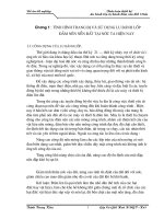
nowadays, it is shown in Figure 1.1 that the amount of renewable energy
consumption has increased. Increase in amount and variety of renewable energy
1
resources is directly proportional with the increase in population, which leads to
increase in energy demand. The renewable energy sources are growing in
importance, but combined still make up less than 15% of world's energy
consumption.
8000
hydroelectric
power
wood
Energy (Trillion Btu)
7000
6000
waste
5000
alcohol fuels
4000
geothermal
3000
2000
solar
1000
wind
0
1945
total
1965
1985
2005
years
Figure 1.1: Renewable Energy Consumption of 1949-2003 [2]
In the last century, mostly coal and fossil fuel sources have been utilized
especially in transportation. According to the current consumption rates, the
scenarios about how long the fossil fuels would last for different cases are not
promising if sufficient precautions will not be taken [3]. There are basically six
types of renewable energies.
Solar energy
The sun can be used to produce heat, light, hot water, electricity, and even
cooling, for homes, businesses, and industry [4]. The two common ways to
produce electricity from the sun are the solar cell technologies also called
photovoltaic cells, and solar-thermal technology. Photovoltaic systems consist
2
of wafers or other conductive materials. When sunlight hits the wafers, a
chemical reaction occurs and electricity is released [5]. They are used in all
kinds of equipments, from calculators and watches to roadside emergency
phones.
Solar-thermal technologies collect the sun's rays with mirrors or other reflective
devices in order to heat a liquid. By heating the liquid, its vapor is used to
activate a generator and produce electricity. There is another way to benefit
from the sun that is buildings` windows constructions are adjusted according to
sunrise and sundown directions. Consequently, consumption of electricity, for
cooling in summer and for warming in winter, would be much more cost
effective.
Geothermal energy
The simplest meaning of geothermal is the heat coming from the Earth. An
extreme amount of heat is contained in liquid rock called magma that is in the
interior of the Earth. These heat zones might be located close to the surface by
the help of the convective circulation. Convective circulation is kind of a deep
circulation of ground water which meets the heat along the fracture zones of the
magma and discharges as hot springs. For direct use applications, the hot water
and/or steam is piped to the surface by drillers in order to generate electricity by
turning a steam turbine. This electricity is used to heat houses or in various
applications for industry.
Hydroelectricity
Hydropower converts the energy of the flowing water into electricity. The
quantity of electricity depends on the volumetric flow rate of the water and the
height of water surface from the turbines. Hydropower plants produce about 24
percent of the world's electricity and supply power to more than 1 billion people
all over the world [6].
3
Wind Energy
The energy from the wind can be collected by wind turbines and windmills to
generate electricity. Wind turbines can be used as stand-alone applications, or
they can be built close together called wind farm. Electricity acquired from the
stand-alone turbines is usually used for water pumping or communications
whereas in the wind farms, hundreds of turbines provide electricity to the power
grid. Other utilities of the wind turbines are charging batteries, pumping water,
and grinding grains of agricultural products [7].
Wind power stations can be constructed quicker than other conventional sources
[8]. Further, wind power has no constraints on any other non-renewable energy
sources that acquiring process of the electricity from the wind turbines is
independent of fuel consumption. The independency on any other type of energy
is very advantageous during obtaining electricity from renewable energy in rural
areas since transportation and cost of the fossil fuel is sometimes difficult to
supply for far villages. For this reason, small turbines can be used effectively in
the villages to compensate the energy needs.
Biomass energy
Biomass is an important source of energy worldwide and is abundantly available
on earth. Many other types of biomass energy can be used now which consists
of trees, agricultural crops and associated residues like plant fiber, animal
wastes, and organic industrial waste [9]. Emission from burning of biomass is
carbon dioxide neutral since it absorbs the same amount of carbon dioxide when
growing as a plant. Biomass can be used as a solid fuel, or converted into liquid
or gaseous forms. It can be used to produce electric power, heat, chemicals, or
fuels. There are basically three types of biomass applications:
Biofuels: Biomass can be directly converted into liquid fuels, to be used in
transportation such as cars, trucks, buses, airplanes, and trains.
Biopower: Biomass can be burned directly or converted into liquid or gas state
to generate electricity or industrial process heat and steam.
4
Bioproducts: Petroleum based products can be substituted by bioproducts which
are not only made from renewable sources also they usually requires less energy
for production.
1.2 Biomass Energy Potential in Turkey
Lack of energy for the future is threatening the world, so as Turkey. Turkey is
able to compensate the energy need of the country from self natural energy
sources. Since Turkey cannot utilize its energy potentials effectively, some
precautions must urgently be taken to compensate the future energy need.
Renewable energy is one of the most important alternatives to avoid this
approaching possible danger.
There are mainly six types of renewable energy sources in Turkey which are:
solar, geothermal, hydropower, wave, wind, and biomass. Among them,
biomass supplies 10% of the total energy consumption of Turkey [10]. Also, the
technology required for the provision of the biomass energy is not as
complicated and costly as the other type of renewable energies.
1.3 Balaban Valley Project
Turkey, once producing its agricultural products exceedingly, now imports even
some of the major agricultural products. This condition has been developed
throughout the years and has some important reasons. In Turkey, there has been
a large migration from rural areas to big cities in the last 50 years. Additionally,
in 60`s some European countries needed cheap labor, so because of the
economical reasons, unequipped people, in rural areas, started to migrate to
these countries. Now, nearly 30% of Turkish population lives in villages. As a
consequence, the number of the farmers decreased proportionally.
In the last 50 years, high inflation rates, resulted in high cost of fertilizers and
pesticides and especially fuel in agricultural areas. This is one other main reason
for the insufficient utilization of agricultural potential in Turkey.
5