Static loading tests on PHC piles installed in gouted boreholes
Bạn đang xem bản rút gọn của tài liệu. Xem và tải ngay bản đầy đủ của tài liệu tại đây (622.07 KB, 11 trang )
<span class='text_page_counter'>(1)</span><div class='page_container' data-page=1>
<b>Transport and Communications Science Journal </b>
<b>STATIC LOADING TESTS ON PHC PILES INSTALLED IN </b>
<b>GOUTED BOREHOLES </b>
<b>Le Thanh Trung1<sub>, Nguyen Duc Manh</sub>2</b>
1<sub>Thu Dau Mot University, No 6 Tran Van On Street, Binh Duong, Vietnam</sub>
2<sub>University of Transport and Communications, No 3 Cau Giay Street, Hanoi, Vietnam</sub>
ARTICLE INFO
TYPE:Research Article
Received: 5/10/2020
Revised: 30/10/2020
Accepted: 6/11/2020
Published online: 25/01/2021
<i> </i>
<i>*<sub> Corresponding author </sub></i>
Email: ; Tel: (+84) 988819932
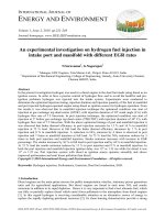
<b>Abstract. </b>A static loading test program on PHC piles installed in grouted boreholes was
performed to evaluate the bearing capacity of PHC Pile calculated basing on Standards TCVN
10304-2014, TCVN 11823-10.2017, and TCVN 7888-2014. The soil profile consists of silty
sand deposited on fat clay and underlain by silty sand. The followed soil layers are lean clay
and silty sand. The diameter PHC piles were installed inside the grouted
600-mm-diameter boreholes into about 60-m depth below the existing grades. 28 days after installing
piles, the static loading test were conducted. The pile test results have shown that the ultimate
capacities of the tested PHC piles are about 142 to 184% greater than those calculated from
Standards of TCVN.
<b>Keywords: </b>PHC piles, Static Loading Test, bearing capacity, Movements, Grouted Boreholes.
©<i><b> 2021 University of Transport and Communications </b></i>
<b>1. INTRODUCTION </b>
</div>
<span class='text_page_counter'>(2)</span><div class='page_container' data-page=2>
PHC pile foundation is currently the trend applied to many different types of construction
works in Vietnam today.
Practically applying this type of pile, in order to improve the load capacity, in addition to
designing to increase the diameter and prolong the length of the pile, the pile is built with
grouted borehole method or erosion then pressed to the design depth. With the lead drilling
technique, during the drilling process, a content of cement is mixed into the drilling grout,
contributing to the improvement of the bearing capacity of the PHC pile. This has led to the
prediction of the pile load capacity according to current standards when the design has a large
deviation value compared with the field pile compression test results [2]. In this study, using
design parameters, ground soil and the test results of static testing of PHC piles constructed
with grouted borehole method from the actual project in Nhon Binh, Quy Nhon city, Binh
Dinh province to conduct accumulating single pile axial load capacity according to current
Vietnamese standards, and at the same time analyzed with static test results of single pile and
ground conditions. The initial research results serve as a basis for orientation for further
research on this issue, in order to further improve the standard system for calculating this
PHC pile foundation in our country in the coming time.
<b>2. THEORETICAL BASIS FOR FORECASTING LOAD CAPACITY OF PHC PILES </b>
<b>CONSTRUCTED BY CONDUCTIVE DRILLING </b>
The axial load capacity of the pile in general, PHC pile in particular is divided into 2
types, according to the material and according to the ground [3]. Similar to other types of pile
foundations, in order to ensure the bearing capacity according to the material, the extreme
load capacity will be calculated based on the strength of the pile materials, specifically
considering the simultaneous work. of reinforcement and concrete with coefficient of working
conditions when these materials work under adverse conditions. In terms of pile load capacity
according to the ground, designed to ensure the bearing capacity of the building transmitted
down through the pile to the ground layers. Currently, most of the calculation views agree to
divide the pile load capacity according to the ground, including 2 components: resistance due
to friction along the pile and compression resistance at the pile tip. Or to be specific, the
longitudinal friction resistance component is the jet component of the ground around the pile
body arising from part or all of the work load transmitted along the pile. The pile tip
resistance component is the pressure of the ground under compression at the tip of the pile
generated by the remaining part of the work load transmitted down to the pile tip.
In this study, the main problem is to pair mainly on the pile load capacity according to the
foundation soil and the pile structure with the theoretical basis of forecasting the pile load
capacity currently mainly applied according to TCVN 10304-2014, TCVN11823: 2017 and
TCVN7888: 2014.
The extreme load capacity of the pile includes the total extreme shear resistance between
the soil and the pile body on the side of the pile, together with the extreme soil support at the
tip of the pile
Qu = <i>u</i>
<i>f lsi i</i>. +<i>A qp</i>. <i>p</i> (1)According to TCVN 10304-2014 is determined as follows
</div>
<span class='text_page_counter'>(3)</span><div class='page_container' data-page=3>
where: <i>N’c, Nq</i> for coefficient of soil load capacity under the pile tip; q’γ,p for effective
pressure of coating at pile tip elevation; c for non-draining cohesion of the soil layer at the tip
of the pile; Ap : Pile tip area.
Average resistance strength on piles can be determined as follows:
For cohesive soil, the average strength of the resistance on piles in the ith layer can be
determined by the method α, according to the formula:
<i> fsi</i> = <i>α.cu,i </i>(3)
where:<i>cu,i</i>for non-drainage resistance strength of the "i" soil layer; α for coefficient depends
on the characteristics of the soil layer on the adhesive layer, the type of pile and the method of
lowering the pile, consolidation of the soil during construction and the method of determining
the soil <i>cu</i>.
For loose soil, the average strength of the resistance on the pile body in the “i” soil layer:
<i> fsi</i> = <i>ki.</i> <i>v,z.tgδi </i>(4)
where: <i>ki</i> for coefficient of soil horizontal pressure on the pile, depending on the type of pile
(driving, pressing) or replacement pile (bored pile or barrete); <i>v,z</i> for average vertical
effective normal stress in the "i" soil layer; <i>δi</i> for friction angle between the ground and the
pile.
Meanwhile at the standard TCVN 11823-10.2017 The permissible load capacity of the
pile according to the ground is determined by the formula:
The rated surface unit resistance is determined as follows:
For loose land
<i> fsi</i> = 0.0019.<i>Ntb</i> (Mpa) (5)
For sticky soil
<i>fsi</i> = <i>α. cu,i </i>(Mpa) (6)
where: <i>α</i> for adhesion coefficient depends on <i>cu,i</i> value (el Caquot & Kerisel):
<i> α</i> = (1+<i> cu,i</i>2)/(1+7*<i> cu,i</i>2) (7)
<i>Ntb</i> for number of hammer for SPT test count of soil layer "i" along the pile; <i>cu,i</i>for average
undrained shear strength of the “i” soil layer along the pile.
The nominal pile tip unit resistance qp is determined according to Meyerhof's method:
<i> qp</i> =0, 38.(<i>N</i>60).<i>Db</i>
<i>D</i> (8)
where: <i>N60</i> for number of hammers in the typical SPT test near the tip of the pile adjusted for
the covering layer pressure; <i>D</i> for width or diameter pile (mm); <i>Db</i> for length of pile
</div>
<span class='text_page_counter'>(4)</span><div class='page_container' data-page=4>
In addition, in calculating the load capacity of the pile, the design engineer needs to
calculate and check the PHC pile structure according to TCVN 7888-2014 as follows:
The calculated axial compressive resistance of the pile (<i>Ra</i>) is given to provide
information for the selection of pile material load during the design and selection of suitable
construction equipment.
The axial compressive resistance calculated according to the pile material is calculated by the
following formula:
2.( ).
3.5 4
<i>cu</i> <i>ce</i>
<i>aL</i> <i>O</i>
<i>R</i> =
−
<i>A</i> (9)where: <i>R</i>a for calculated axial compressive resistance of the pile, kN;<i>A </i>for cross sectional area
of the pile, mm2<sub>;</sub><i><sub>σ</sub></i>
ce for effective internal stress of the concrete pile; <i>σ</i>cu for design
compressive strength of concrete.
<b>3. PROJECT SUMMARY AND GEOLOGICAL CONDITIONS </b>
<b>3.1 General information of project </b>
The social housing project of Nhon Binh Ward, Quy Nhon City is built on a lot of land
nearly 46034 m2. The project includes 5 units of 10-11 floors, technical infrastructure,
kindergarten, low-rise housing area. Each house unit is equivalent to grade II building.
Figure 1. Location of the project and architectural landscape of work.
<b>3.2. Pile construction technology </b>
<b>3.2.1. Working procedure </b>
</div>
<span class='text_page_counter'>(5)</span><div class='page_container' data-page=5>
water). Finally, pull out the earth auger completely, inserting the PHC pile into borehole with
its own weight.
<b>3.2.2. Excavating soil </b>
Excavating soil from the ground to designed depth by drilling with air compressor
(Figure 2). During construction, the excavating soil shall be collected by excavator. Borehole
will be kept as vertical during drilling.
Figure 2. Excavating soil to designed depth by double machine.
<b>3.2.3. Cement milk grouting </b>
Before and after pile-inserting into the hole, hardening cement mile grouting shall be
filled respectively. After excavation reach to the designed depth, the cement milk grouting
shall be injected into the borehole. Cement milk grouting will be mixed at mixing machine
based on approved mix design. Root milk grouting goes through drillting rod to bottom of
drilled hole with designed volume. Fixed milk grouting to be pumped from top of borehole
after one day. Cement milk grouting take a role in strengthening bearing capcity at pile tip and
recovering & rebounding side friction of pile. Cement milk grouting should be complied with
requirement of JRA code. The time for slurry to get hard approximately 2-4 hours.
<b>3.2.4 Installing pile </b>
</div>
<span class='text_page_counter'>(6)</span><div class='page_container' data-page=6>
Figure 3. Photos of pile construction technology.
<b>3.2.5 Material </b>
Hardening cement milk grouting, compressive strength test should be carried out at
laboratory and site (R28>=20MPa). During mixing, the concrete temperature should be
managed constantly. Parameter mix design and raw material for pile in 1m3 is in Table 1.
Table 1. Parameter of cement milk grouting.
<b>Cement </b> 3,330 kg
<b>Water </b> 2,330 L
</div>
<span class='text_page_counter'>(7)</span><div class='page_container' data-page=7>
PHC pile shall be manufactured in accordance with JIS A 5373 (or equivalent
Vietnamese code) is in Table 2.
Table 2. Parameter of PHC pile.
<b>Diameter </b>
<b>(mm) </b>
<b>Class </b> <b>Effective </b>
<b>Pre-stress </b>
<b>(N/mm2) </b>
<b>Thickness </b>
<b>(mm) </b>
<b>Compressive </b>
<b>Strength of </b>
<b>Concrete (N/mm2) </b>
<b>Allowable </b>
<b>Axial Force </b>
<b>(tonf) </b>
600 A 4.0 90 80 155
<b>3.4. Geological conditions </b>
From exploration and revealing the formation of data analysis, site 75m depth within the
scope of the foundation soil is mainly consisted of the glue powder in the soil, sand silt and
fine sand. According to its sedimentary s, the differences between the genetic types and its
physical and mechanical properties can be divided into nine engineering geology layer. (1)
Clay mixed with roots of plants; (2) summer sand is mixed with grit, dust, gray gray, dark
gray, porous state;(3) Clay, mixed organic, sand clamp, gray gray, green gray, flowing to
plasticity;(4) Grained sand is small mixed with grit, dust, gray-brown, dark gray, medium
tight state;(5) Mixed organic clay, clamshell, sand clamp, gray-brown, dark gray, soft to
flexible state;(TK1) Medium grain sand, mixed with shells, gray gray, medium tight state;(6)
Fine to coarse-grained sand, gray-gray, yellowish-gray, dark-gray in color, the state is tight in
some places;(TK2) Clay mixed organic, gray brown, dark gray, from hard to soft plastic
state;(TK3) Mud bag mixed with clay;(7) Medium to coarse grained sand, yellowish gray,
white gray, very tight state;(8) Pebbles mixed with gravelly sand, yellow gray, white gray, the
state is very tight;(9) Strong to medium fracture weathered granite, reddish-brown,
gray-white. The foundation of the project is designed on PHC piles with diameter D600mm ,
constructed by the grouted borehole method with a borehole diameter of 600mm, in
compliance with the instructions in TCVN 7201-2015.
<b>4. STATIC LOAD TEST AND ANALYSIS</b>
<b>4.1. Test pile </b>
The test pile is 600mm in diameter, 60.0m long with the number of three piles. The
corresponding test piles are TN1, TN2 and TN3 in boreholes from HK1 to HK4 respectively,
it shows in Fig 3. The proposed design load is 250 tons, the experimental load is 500 tons.
The test piles are constructed extending up to the natural soil surface and tested as working
piles throughout their length from natural ground.
Three rook pile staic load tests are respectively for TN1, TN2, and TN3. The maximum
load tests of three root piles are conducted according to the 5000kN. It is presented in Table 3.
Table 3. Mechanical parameters of borehole.
<b>Hole </b>
<b>no. </b>
<b>The </b>
<b>soil </b>
<b>Thickness </b>
<b>(m) </b>
<b>SPT - N </b>
<b>value </b>
<b>Hole </b>
<b>no. </b> <b>The soil </b>
<b>Thickness </b>
<b>(m) </b>
<b>SPT - N </b>
<b>value </b>
<b>HK1 </b> (1) 0.5 - <b>HK3 </b> (1) 0.6 -
(2) 5 5 (2) 3.5 3
(3) 30.5 3 (3) 25.9 3
(4) 3 11 (4) 1 13
</div>
<span class='text_page_counter'>(8)</span><div class='page_container' data-page=8>
(6) 3.2 39 (6) 5.3 25
(TK2) 1 12 (TK2) 3.8 10
(6) 10 39 (6) 8.4 35
(7) 6 67 (7) 5 58
<b>HK2 </b> (1) 0.5 - <b>HK4 </b> (1) 0.5 -
(2) 4.3 4 (2) 3.7 6
(3) 24.9 3 (3) 24.2 4
(4) 1.6 11 (4) 3.4 5
(5) 4.7 4 (5) 4.2 7
(TK1) 3 7 (TK1) 3 10
(5) 13.5 40 (5) 9.6 17
(7) 2.4 86 (6) 22.9 30
(8) 1.6 >100 (7) 0.6 >100
<b> </b> (9) 2 >100 (9) 0.9 >100
Figure 4. Layout of test piles.
<b>4.2. Test load </b>
The determination of the load capacity of the pile is done according to the Vietnamese
standard TCVN 9393-2012, the loading process includes many levels of load, each increase
will be 25% Qu (so there will be 8 ÷ 10 levels of load). Settlement will be recorded at: 0
minutes, 15 minutes, 30 minutes, 45 minutes, 1 hour, 1.5 hours, 2 hours, 3 hours, 4 hours,....
Only increase load to the next level if the settlement of the pile has been stable (settlement of
the pile by or less than 0.1mm within 30 minutes for sand, 60 minutes for clay).
According to Vietnamese regulations, there are 2 experimental cycles as follows:
Cycle 1 is from zero to Qdesign down zero is intended to eliminate the anomalies in the pile
foundation.
Cycle 2 is from zero Qdesign to Qu down zero to collect data in the most reliable way
</div>
<span class='text_page_counter'>(9)</span><div class='page_container' data-page=9>
The working load of the test pile estimated by the design unit is about 250T. The
maximum test load applied to the pile is 200% of the design load, that is 500T. The
experiment goes well, under maximum load test pile settlement of pile top which is less than
60 mm (1%D), with no obvious increase subsidence phenomenon, and the test pile have no
reach the ultimate bearing state.
<b>4.3. Test results and analysis </b>
The results of pile static load test are shown in Table 4. The Q-S curve of TN1, TN2,
TN3 root pile is shown in Figure 5.
Table 4. Static load test results.
<b>Pile name </b> <b>The maximum test </b>
<b>load/Ton </b>
<b>The maximum test load of </b>
<b>pile top settlement/mm </b>
<b>TN1 </b> 500 19.24
<b>TN2 </b> 500 15.61
<b>TN3 </b> 500 10.84
See from Figure 5, when the maximum load test is 500 tons, which indicates that the test
pile settlememt is stable at all levels of loads, the Q – S curve lines are similar with slow
deformation and no obvious bending steep fall, and the settlement was less than 60 mm,
namely 3 root pile tests did not reach the limit state, and the ultimate bearing capacity can be
thought not less than 500 tons, which is adopte in this paper, in order to better forecast the
load settlement value of origin software software load – settlement for polynomial fitting, and
the fitting result is shown in Figure 2. Fitting curve equation is y = ax2 + bx + c, where, a =
3e-6, b = 0.0054, c = 0.2914, and the results show that R2 = 0.9916, and the fitting is good.
</div>
<span class='text_page_counter'>(10)</span><div class='page_container' data-page=10>
<b>5. BEARING CAPACITY CALCULATION, COMPARISON AND ANLYSIS </b>
Based on geological conditions and structural parameters of the test pile. We can have
calculated bearing capcity of TN1, TN2 and TN3. Specifically, the bearing capcity of TN1
pile is calculated to boreholes HK1 and HK2. While the bearing capcity of TN2 pile is
calculated to boreholes HK3 and TN3 pile is calculated to boreholes HK4. Results of
calculation to predict the bearing capacity of the test piles are presented in Table 5.
Table 5. Comparison and analysis results.
<b>Calculation </b>
<b>method </b>
<b>TCVN </b>
<b>10304-2017 </b>
<b>/ kN </b>
<b>TCVN </b>
<b>11823.10 -2017 </b>
<b>/kN </b>
<b>TCVN </b>
<b></b>
<b>7888-2014/k</b>
<b>N </b> <b>Test/</b>
<b>kN </b>
<b>Qs </b> <b>Qp </b> <b>Qu </b> <b>Qs </b> <b>Qp </b> <b>Qu </b> <b>Qu </b>
HK1 2712.56 659.80 3372.36 4077.33 383.99 4461.32 6867
HK2 1661.19 707.28 2368.47 2507.20 373.59 2880.79 6867
HK3
1499.39 672.20
2171.59
2266.39 376.95
2643.34 6867
>
5000
HK4 2321.82 631.04 2952.86 3771.15 310.68 4081.83 6867
The average 2048.74 667.58 2716.32 3155.52 361.30 3516.82 6867
The ratio ≤ 1.84 ≤1.42 ≤ 0.73
We can see from the result of comparison: (1) the bearing capacity of single pile static
test determined according to TCVN 9393-2012 gave the result 5000kN. This value is 1.84
times greater than the value of the bearing capacity forecasted according to TCVN10304:
2014, 1.42 times greater than the value of forecasted bearing capacity according to TCVN
11823-2017 but it is 0.73 times greater than the forecast according to TCVN 7888: 2014. (2)
in both TCVN 10304-2014 and 11823-10.2017, limit the lateral resistance of the percentage
of th ultmate bearing capacity is greater than the resistance ratio of the ultmate end, which
shows that the engineering PHC pipe piles for friction piles mechanically are mainly
composed of pile side resistance. (3) the bearing capacity of pile approach 73% of the
material bearing capacity of the pile. This can be explained by the fact that when constructing
the PHC pile with grouted borehole method, by mixing a quantity of cement into the drilling
grout, the pile body friction and the pile tip resistance have been significantly improved. The
drilling fluid mixed with the cement milk increases the contact between the pile and the
ground, which significantly improves the load capacity of the PHC pile, and it also reinforces
the soil around the pile. So, it helps us to better exploit the bearing capacity of the pile
according to the material condition of the PHC pile.
<b>6. CONCLUSIONS </b>
</div>
<span class='text_page_counter'>(11)</span><div class='page_container' data-page=11>
Under the same ground conditions and design load, the PHC axial load capacity when
forecasting according to different current Vietnamese standards gives different results, the
difference up to 87% is very significant.
The results of this study show that, the existence of three interdependent Vietnamese
standards guiding pile foundation load prediction, especially with PHC pile foundation
constructed by grouted borehole method, still exist differences. especially when forecasting
bearing capacity for design, so it is necessary to have more detailed and specific studies in the
future.
<b>REFERENCES </b>
[1]. TCVN 7888-2014. Pre-stressed centrifugal concrete pile. Ha Noi, 2014.
[2]. TCVN 9393-2012: Pile - Site test method by axial static load. Ha Noi, 2014
[3]. TCVN 10304-2014. Pile foundations - Design standards. Ha Noi, 2014
[4]. TCVN 11823-2017. Design of road bridges. Ha Noi, 2017.
[5]. TCVN 7201-2015. Centrifugal concrete pile lowering drilling - Construction and acceptance,
2015.
[6]. JIS A 5373, Pre-stressed spun concrete piles (PHC pile).
[7]. Ha Noi Construction Design Survey Consultancy Joint Stock Company Report the results of
engineering geological survey "housing project in Nhon Binh commune, Quy Nhon city, Binh Dinh
province", 2020.
[8]. Consultancy and technical investment of foundation works, D600mm concrete pile static
compression test results, The project "Housing project in Nhon Binh commune, Quy Nhon city, Binh
Dinh province", 2020.
[9]. X. Zhou, G. Fang, A Study of PHC Pipe Pile Vertical Ultimate Bearing Capacity Calculation
Method and its Numerical Simulation Analysis, MATEC Web of Conferences, 22 (2015) 04024.
[10]. L. Prekop, Verification of the Vertical Bearing Capacity of a Reinforced Concrete Pile, Procedia
Engineering, 190 ( 2017 ) 536-539. />
[11]. K. Rui et al., Field test on Ultimate bearing capacity of Composite Pile made up of Jet-mixing
Cement and PHC Pile with Core Concrete. IOP Conf. Series: Materials Science and Engineering, 392
(2018) 022010. />
</div>
<!--links-->