Bài giảng công trình trên hệ thống thủy lợi valves and gate
Bạn đang xem bản rút gọn của tài liệu. Xem và tải ngay bản đầy đủ của tài liệu tại đây (758.41 KB, 28 trang )
CHAPTER 6. VALVES AND GATES
1. INTRODUCTION
What are valves and gates?
Which types are valves and gates classified?
1.1. Definition
Valves and gates play as a part of hydraulic structures;
are installed at outlets of the structures to control water
level on reservoir and adjust discharge at the outlets.
1
1.2. Classification
1-Based on function: Service, maintenance, emergency gates
1.2. Classification (cont.)
2-Based on pressure transmission:
to piers or abutments.
to gate sill.
a)
®)
b)
e)
c)
g)
d)
h)
1.2. Classification (cont.)
3-Based on mode of operation:
to let water out under the gate.
to let water out over the gate.
Combination between the above types
a)
b)
c)
1.2. Classification (cont.)
4-Based on form of gates: Plain, radial, drum, flap, roller,
fabric gates.
4-Based on form of gates (cont.): Radial gate
4-Based on form of gates (cont.): Drum and sector gates
4-Based on form of gates (cont.): Flap gate
4-Based on form of gates (cont.): Roller gate
1.2. Classification (cont.)
5-Based on moving mechanism: Gates are movedelectrically.
mechanically.
automatically by water pressure.
6-Based on material: Gates made of steel, reinforced
concrete or other synthetic materials.
1.2. Classification (cont.)
7-Based on position: Crest and submerged gates.
a)
b)
®)
c)
e)
i)
d)
g)
k)
h)
l)
m)
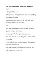
Types of crest gate
a) Plates; b) Vertical lift gate; c) Radial gate; d) Roller gate; ®, e) drum and sector gate;
g) Roof gate; h) Horizontal axial plain gate; i) Vertical axial gate; k) Horizontal axial
frame gate; l) Braked gate; m) Air-made gate.
a)
b)
®)
c)
g)
e)
1
2
d)
2
3
3
1
h)
i)
k)
Submerged valves.
a) Plain valve; b) Radial valve; c) Key valve; d) Horizontal axial plate valve; ®) Hollow-jet
valve; e) Cone dispersion valve; g) Roller valve; h) Sphere valve; i, k) Pillar valves.
13
1.2. Classification (cont.)
8-Tidal barrage and surge protection gates
2. CALCULATION OF PLAIN GATE (VERTICAL LIFT)
2.1. Forces acting on the gate
Hydrostatic pressure;
Hydrodynamic pressure;
Weight of the gate;
Frictions;
Forces caused by floating objects.
2.2. Necessary driving forces to open or close the gate
a. General formulas:
Opening driving force:
P1 = K1G + K 2 (T1 + T2 ) − K '.G d
Closing driving force:
P2 = K1.G d + K 2 .(T1 + T2 ) − K '.G
G- Weight of the gate;
T1- Friction between gate and abutment;
T2- Friction at watertight components;
Gd –Weight of counterpoise;
K1, K2, K’: Safety factors: K1 =1,1; K2 =1,2; K’ =0,9.
b. Specification of items
*Calculation of G: (for gates made of steel)
G = g.H.l0
(N)
g- averaged weight of the gate/unit (N/m2).
H- Height of gate (m); l0- Width of gate (m).
g was determined based on catalogs of gates or
experimental formulas.
*Calculation of Gd : depend on the designer
*Calculation of T1- Friction between gate and abutment:
b. Specification of items (cont.)
*Calculation of T1- Friction between gate and abutment:
+ If gate slips against abutment:
T1 = f.Wo
f- Friction factor;
Wo- total water pressure acting on whole gate
+ If gate moving is supported by wheels:
R- Radius of wheel;
W
( f .r + f1 )
T1 =
R
r- Radius of axle of wheel;
f- Sliding friction factor between axle and wheel;
f1- Rolling friction of wheel;
W: total water pressure on each of wheels;
b. Specification of items (cont.)
*Calculation of T2- Friction at watertight components;
T2 = f2.W
f2- Friction factor
W- Total water pressure acting on whole gate
In case of crest gate:
T2 = f2.a.γγh
a- width of watertight component;
h: water depth.
19
2.3. Structural analysis of the gate
a. Structure of the gate:
1. Principal beams; 2. Sub-beams; 3. Inner columns; 4.
Border columns; 5. Braces; 6 Watertight surface plate
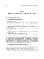
2.3. Structural analysis of the gate (cont.)
b. Determination of principal beams:
Method:
Choose the number of principal beams (n);
Divide the diagram of water pressure into n parts
which has the same amount of total water pressure;
Position of each beam is the centroid of each part of
water pressure, correlatively.
A
h1
H
h3
h2
yk
a
A
b
a)
a
H/n
b'
d'
f'
A
H/n
d
H
h2
yk
h1
H/n
f
C
D
b'
d'
B
H/n
b)
a: In case of crest gate; b: In case of submerged gate
D'
b
d
BC/n
BC/n
BC/n
For crest gate:
(
2 H 3/2
3/2
yk =
k − (k − 1)
3 n
)
yk- the distance from water surface to k-principal beam
n- number of principal beams;
H- water depth.
For submerged gate :
yk =
[
2 H
(k + β)3 / 2 − (k − 1 + β)3 / 2
3 n+β
]
na 2
β= 2
H − a2
a- the distance from water surface to crest of submerged gate
22
3. CALCULATION OF RADIAL GATE
3.1. Forces acting on the gate
Hydrostatic pressure;
Hydrodynamic pressure;
Weight of the gate;
Frictions;
Forces caused by floating objects.
3.2. Necessary driving forces to open or close the gate
a. General formulas:
T2
T1
Opening driving force:
T0
P1 = K1.To + K2.(T1 + T2)
W
l4
α
Closing driving force:
Q
G
P2 = K2.(T1 + T2) - K’.To
g0
h1
W
To- force to win weight of the gate (G);
T1- force to win friction at the hinge;
T2- force to win friction at watertight components;
K1, K2, K’: Safety factors: K1 =1,1; K2 =1,2; K’ =0,9.
l3
b. Specification of items
T0 = G
T2
T1
l3
l4
T0
f .Q.r
T1 =
l4
W
l4
α
Q
G
e
f 2 P R +
2
T2 =
l4
h1
l4- tay đòn của các lực T.
Q- lực tác dụng tổng hợp tại khớp quay.
r- bán kính trục quay.
f- hệ số ma sát tại khớp quay.
g0
W
l3
f2- hệ số ma sát tại thiết bị khít nớc.
P- tổng áp lực lên thiết bị khít nớc.
e- chiều rộng thiết bị khít nớc.
R- bán kính mặt van cung.