Tài liệu New Network Architecture Digivance® Simulcast Networks Reduce Network Costs and Improve Quality of Service ppt
Bạn đang xem bản rút gọn của tài liệu. Xem và tải ngay bản đầy đủ của tài liệu tại đây (1.48 MB, 8 trang )
New Network Architecture
Digivance
®
Simulcast Networks Reduce
Network Costs and Improve Quality of Service
WHITE PAPER
Improving Grade of Service (GOS) While
Reducing RF Channels
Wireless service providers are adopting new deployment strategies
to reduce network costs and improve quality of service. In one
urban market, a major national wireless service provider has
improved network traffic loading and significantly boosted network
RF performance by centralizing radio equipment and deploying
digital RF transport technology. The digital RF transport systems
operate in simulcast mode and reproduce the signal at radiating
points throughout the network. The new network architecture has
produced trunking and channel re-use performance gains that
enable the service provider to deliver greater GOS while reducing
the number of RF channels.
To achieve greater capacity with fewer RF channels, network
designers used two or more ADC Digivance digital RF transport
systems operating in “simulcast” mode at radiating points
throughout the network. This white paper describes that simulcast
network architecture, network traffic loading improvements and
how the team determined the number of RF channels needed to
achieve the desired GOS.
Digivance
®
Simulcast Networks
Reduce Network Costs and Improve Quality of Service
New Network Architecture
New Network Architecture
Page 3
What is "Simulcast"?
A wireless simulcast communications system is defined
as a signal (or group of signals) that is transmitted from
a central transceiver and identically reproduced to
several radiating points, with all received signals from
these radiating points sent for recovery at the central
transceiver’s receive circuitry.
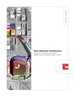
In the case of Digivance technology, the “central
transceiver” is the Base Transceiver System
(BTS)/Digivance host location, and the “several radiating
points” are multiple Digivance remote units, as shown
in this example of a Long-Range Coverage Solution
(LRCS) simulcast deployment diagram:
ADC’s patented Digivance digital RF spectrum transport
solution is uniquely suited as the infrastructure of a
simulcast network due to the inherent qualities of a
digital fiber system. These benefits include:
• Highest optical budget in the transport industry
• Exceptional RF performance throughout entire
optical budget
• Lowest reverse path cascaded noise figure in the
transport industry
• Present WDM and CWDM optic capability, with
future DWDM capability
How Does a Digivance Simulcast
System Create a Network Traffic
Loading Improvement?
The benefits of simulcast coverage in the service
provider’s urban network are due to a reduction in the
number of BTS sectors and an increase in channel loading
per sector. This improves trunking efficiency (remember:
calls cannot trunk between sectors). In the urban LRCS
network, the new architecture reduced by 30 percent or
more of the total number of RF channels required on a
multiple link transport system for a specified amount of
user grade of service. The percentage reduction
depended on the number of radiating points and trunks
required for the coverage area.
In all communications systems that carry more than one
user at a time, several communication links (i.e. voice
“trunks”) must be provisioned to allow for all
anticipated users to gain reasonable access to the
network. What determines “reasonable access” is the
designated “grade of service” (GOS), which is the
acceptable amount of network blocking of incoming call
attempts. Typical wireless network designs in the United
States provision channels to provide voice services at a
GOS of approximately 2 percent, with data services
typically provisioned at a GOS of 4 to 5 percent.
To determine the number of RF channels (voice trunks),
the GOS and anticipated traffic intensity (Erlangs) must
be known. Conversely, if you know the number of
voice trunks available and the GOS, you can calculate
traffic intensity supported.
“Trunking efficiency” is simply the observation that the
more voice trunks available - the less the chance of
blocking, and is best explained by the Erlang B (non-
queuing requests) formula:
Where:
B = Blocking% (GOS)
A = Offered Traffic Load (Erlangs)
N = Number of Available Trunks
BTS
Site
Controller
BTS
Sector
1
Interface
Panel
FP 3:1
RP 3:1
Host 1
Host 2
Host 3
BTS
Sector
1
Interface
Panel
FP 2:1
RP 2:1
Host 4
Host 5
Remote
1
Remote
2
Remote
3
Remote
4
Remote
5
A
N
N!
B=
i
i!
i=0
N
A
∑
Core Urban Market - A “Real World”
Case Study
Here is an actual service provider’s market application of
LRCS in two separate 2:1 simulcast configurations. In
the original metro “RF hotel” configuration of five
radiating points (a traditional BTS deployment of one
radiating point per sector), the service provider
operated five BTS sectors dedicated to five separate
radiating points in strategic locations to obtain desired
capacity and coverage in the metro core, as shown in
diagram below:
With average Radio Frequency channel (RFc)
provisioning for this configuration of six RFcs (a
maximum of 17 interconnect voice trunks) per sector,
the acceptable offered interconnect load (GOS = <2%)
was 10.6 Erlangs per sector.
Given an interconnect traffic intensity total in Erlangs =
(10.6E * (# of sectors)), any two sectors within this BTS
would support 21.2 Erlangs at 2% GOS.
After the five LRCS sectors were optimized and
confirmed to be operating with excellent statistics, the
urban market began to test the ADC recommended
simulcast strategies.
This is a diagram detailing the customer conversion to
one sector of simulcast:
By combining two of these radiating points into a single
BTS sector and increasing the base radio count of that
sector to 10RFcs (26-29 interconnect voice trunks
maximum), trunking efficiencies are increased to 21.1
Erlangs at 2% GOS traffic support on a single simulcast
sector.
Capacity comparison:
(21.1E)/(21.2E) = 0.995%
Required Radio Frequency Channels:
10RFc(simulcast)/12RFc(RFc S 2 sectors) = 0.833%
An initial conclusion can be drawn that this
configuration allows for virtually identical capacity (at
0.995%) with 17 percent fewer BTS radio channels
required… an impressive number in itself. There is also
an opportunity for data services to realize the benefits
of increased trunking efficiencies of a Digivance digital
simulcast network.
So for the direct connect and packet data services
queuing calculation using Erlang C provisioning is:
In this network deployment, the service provider
realized significant cost savings and found that they
could actually reduce to one sector with nine RFcs from
two sectors averaging 13 RFcs (2 sectors of 6RFc + 7
RFc), a BTS radio reduction of 31percent.
In addition, it was observed that low cost/low power
2:1 splitters and combiners could be used for forward
and reverse paths to couple signals between a single
interface and two host units. This reduced the amount
of interface circuitry required in the network and
produced another cost savings from the simulcast
system. After realizing this savings (and being assured
by continued excellent system performance statistics
and RF measurements) the service provider repeated
this 2:1 simulcast process again with the same results.
New Network Architecture
Page 4
BTS
Site A
Controller
BTS
Site B
Controller
Sector 1
(6RFc)
Sector 2
(6RFc)
Sector 3
(6RFc)
Sector 4
(6RFc)
Sector 5
(6RFc)
BTS
Interface
BTS
Interface
BTS
Interface
BTS
Interface
BTS
Interface
Host 1 Remote 1
Host 2
Host 3
Host 4
Host 5
Remote 2
Remote 3
Remote 4
Remote 5
BTS
Site A
Controller
Sector 1
Sector 2
Sector 3
BTS
Interface
BTS
Interface
BTS
Interface
Host 1 Remote 1
Host 2
Host 3
Remote 2
Remote 3
A N
N
N! (N-A)
i
i!
P(>0)=
A
∑
N-1
+
A N
N
N! (N-A)
i=0
New Network Architecture
Page 5
Final Configuration:
The estimated equipment savings realized for the
service provider’s three sector simulcast application vs. a
five sector application were as follows:
Estimated savings in required BTS and LRCS equipment:
• 7 fewer base radios required (est. as provided by
customer) 7* $5,000 = $35,000
• 50% fewer LRCS-BTS Interfaces required (list, 2
primary panels) 2* $2,900 = $5,800
• 30% fewer high power TX combiners required
2* $3,000 = $6,000
• 30% less Rx Multi-coupling
2* $2,000 = $4,000
Estimated expense in required simulcast equipment:
• 4 Low power splitters and combiners and coaxial
leads 4* $400 = $1,600
Savings realized by converting four sectors to two
simulcasts:
Total Equipment Savings = $49,200 (less expenses)
Additional operational savings:
• Reduced BTS space and power requirement (less
equipment)
• BTS Ops/Field/Perf/Design Engineering support
(fewer RF channels)
BTS
Site A
Controller
BTS
Site B
Controller
Sector 1
(6RFc)
Sector 2
(9RFc)
Sector 3
Sector 4
(9RFc)
Sector 5
BTS
Interface
BTS
Interface
BTS
Interface
BTS
Interface
BTS
Interface
Host 1 Remote 1
Host 2
Host 3
Host 4
Host 5
Remote 2
Remote 3
Remote 4
Remote 5