Tài liệu Digivance® doc
Bạn đang xem bản rút gọn của tài liệu. Xem và tải ngay bản đầy đủ của tài liệu tại đây (447.43 KB, 8 trang )
w w w . a d c . c o m • + 1 - 9 5 2 - 9 3 8 - 8 0 8 0 • 1 - 8 0 0 - 3 6 6 - 3 8 9 1
Spec Sheet
Digivance
®
Long-Range Coverage Solution 800/900, 1900 and
Tri-Band 800/900 and 1900 MHz Systems
Digivance
®
– ADC’s Digital Advantage for Improving Wireless Capacity,
Coverage and Customer Retention
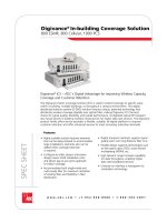
ADC, a leading solution provider for distributing and enhancing wireless capacity and coverage,
offers the Digivance
®
Long-Range Coverage Solution (LRCS). The LRCS improves wireless
networks by extending wireless coverage from existing cell sites to hard-to-reach areas or
distributing capacity from centralized radio suites. The Digivance family offers flexible, scalable
solutions to fit various applications from a single building to a campus to a dense urban center.
Features:
Flexible architecture enables macro network coverage to be distributed over individual or
multiple point-to-point optical RF transport links:
• All-digital transport enables transition to optional capabilities such as free space optics links
and coarse wavelength division multiplexing (CWDM)
• Digital RF transport is transparent to air modulation standards; e.g., iDEN
®
, GSM, CDMA, W-
CDMA, 1xEV-DO
• Remote alarm monitoring from the network operations center (NOC) reduces
troubleshooting time
• SNMP support
• Local alarm networking of multiple systems for monitoring and control
• Tri-band solutions within a dual cabinet, supports future band upgrade
Dual-Band Remote Cabinet
for Tri-Band Solution
800/900 ESMR Host Unit
1900 MHz Host Unit
8 / 0 6 • 1 0 2 9 7 8 A E
Digivance
®
LRCS Tri-Band System
2
w w w . a d c . c o m • + 1 - 9 5 2 - 9 3 8 - 8 0 8 0 • 1 - 8 0 0 - 3 6 6 - 3 8 9 1
Digivance
®
LRCS 800/900, 1900 and Tri-Band 800/900 and 1900 MHz Systems
Overview
With the increasing popularity and reliance on
wireless devices, subscribers expect to have
coverage at any time in any place they may
be. This requires service providers to increase
capacity, which is typically done by adding new
cell sites. However, with city centers becoming
more congested and local government zoning
regulations becoming more stringent, obtaining
permits for new wireless cell sites is becoming
increasingly more difficult. Extending service
to these hard-to-reach areas can be quite
challenging. ADC’s LRCS is a cost-effective
solution for extending or distributing capacity
from base stations to other areas that require
coverage.
Application
The LRCS is the only long-range RF distribution
solution to offer a fully digital platform. By using
patented technology the LRCS digitizes the
entire designated RF band, digitally transports
it over fiber, and reconstructs the signal at
full bandwidth, regardless of modulation
technology. Digital RF transport allows the
signals to be replicated at full dynamic range,
independent of the fiber length, which improves
data throughput. As advanced, high data rate
broadband services are rolled out, networks with
a LRCS backbone will be ready.
ADC’s digital RF transport technology
accommodates enhancements, such as free
space optical laser links instead of physical fiber
connections for even faster deployment and
CWDM capabilities. The CWDM option allows
multiple transmit and receive paths over a single
fiber cable, potentially reducing annual fiber lease
costs. Free space optical laser links and millimeter
wave solutions overcome fiber availability issues.
The LRCS offers a flexible architecture to
distribute wireless capacity. Its versatility and small
size allow service providers to quickly deploy
networks in areas where zoning restrictions often
hinder installation of base stations. Centralization
of base station capacity can also be realized using
LRCS. This allows service providers to further
benefit by reducing capital expenditures and
annual operating costs.
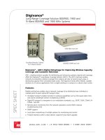
System Description
The LRCS transports digitalized RF signals to
difficult coverage areas such as congested city
center locations, tunnels and canyons. One
point-to-point RF transport link consists of a Host
Unit, Remote Unit, and element management
software.
The LRCS Host Unit is typically rack mounted
at the enhanced base transceiver station (EBTS)
site or co-located with other Host Units at a
centralized base station radio (BR) suite. The RF
signal is transported digitally over fiber optic cable
connecting the Host Unit to a Remote Unit. The
Digivance LRCS Remote Unit is positioned at the
area requiring coverage and interfaces with an
antenna to distribute the RF signal. The distance
between the LRCS Host Unit and Remote Unit
is limited mainly by time delay requirements
of system modulation standards (iDEN
®
, GSM,
CDMA, W-CDMA, 1xEV-DO, etc.), which is
typically several kilometers.
Digivance LRCS Host UnitBase Station
High Power
Duplexer
BTB
48 VDC
Sector Alpha
Sector Beta
Sector Gamma
High Power
Duplexer
High Power
Duplexer
CWDM
CWDM
CWDM
110 VAC
CWDM
Digivance LRCS Remote Unit
110 VAC
CWDM
Alpha
Omni-Cell
Digivance LRCS Remote Unit
Alpha
Omni-Cell
Digivance LRCS Remote Unit
110 VAC
CWDM
Alpha
Omni-Cell
8 / 0 6 • 1 0 2 9 7 8 A E
Digivance
®
LRCS Tri-Band System
3
w w w . a d c . c o m • + 1 - 9 5 2 - 9 3 8 - 8 0 8 0 • 1 - 8 0 0 - 3 6 6 - 3 8 9 1
Host Unit
The rack-mountable LRCS Host Unit is typically
located at an EBTS or a facility building housing
a suite of EBTSs. On the forward path, the
Host Unit digitizes the designated RF band and
digitally transports it over singlemode fiber to the
Remote Unit. On the reverse path, the Host Unit
receives the digitized signal and converts it to
RF. The Host Unit also collects alarm information
from the Remote Unit. For system deployments,
multiple links can be networked together at the
same EBTS site. Host Units can be daisy-chained
together to allow monitoring and control of
multiple links from a single user interface.
Remote alarm monitoring and control of the
LRCS system can also be performed from an
off-site location or NOC. Communications to
the NOC can be performed using a PC with a
standard physical layer protocol.
In addition to sending alarm notifications to the
EMS through software, the LRCS Host Unit also
features front panel alarm reporting. LEDs on the
front panel of the Host Unit will change color
depending on the status of the unit. LED displays
provide information regarding the following
items:
• Power
• System mode (active/standby)
• Indicate faulty unit
• RF conditions
Furthermore, alarm contact closures provide
major and minor alarms. The Host Unit has two
alarm contacts that either report system operation
is seriously affected (major alarm) or system
operation is degraded (minor alarm). The Host
Unit operates on DC power.
Remote Unit
The LRCS Remote Unit is typically in an outdoor
cabinet that is either pole-mounted or mounted
on the side of a building. On the forward path,
the Remote Unit receives the digitized signals
from the Host Unit and converts the signal
back into RF to be distributed via an externally
mounted antenna. On the reverse path, the
Remote Unit digitizes the designated RF band
and digitally transports it over singlemode fiber
to the Host Unit. In addition to sending alarm
notifications to the EMS software, the LRCS
Remote Unit also features front panel alarm
reporting. LEDs on the front panel of the Remote
Unit will change color depending on the status
of the unit. LED displays provide information
regarding the following items:
• Power
• System mode (active/standby)
• Indicate faulty unit
• RF conditions
• Power amplifier fault
• Antenna fault system (VSWR)
Furthermore, alarm contact closures provide a
final level of alarming capability at the Remote
Unit. Major and minor alarms are reported
through these contact alarm closures. The
Remote Unit is powered by an AC source.
Digivance
®
LRCS 800/900, 1900 and Tri-Band 800/900 and 1900 MHz Systems
8 / 0 6 • 1 0 2 9 7 8 A E
Digivance
®
LRCS Tri-Band System
4
w w w . a d c . c o m • + 1 - 9 5 2 - 9 3 8 - 8 0 8 0 • 1 - 8 0 0 - 3 6 6 - 3 8 9 1
Digivance
®
LRCS 800/900, 1900 and Tri-Band 800/900 and 1900 MHz Systems
Alarm and Management System
ADC's Digivance EMS provides operational
and maintenance capability for the
LRCS. The Digivance
EMS consists of a
personal computer (PC) using a Windows
®
operating system, ADC furnished Java-
based software package; an ASCII based
RS-232 capable terminal, and RS-232
cables.
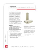
The EMS can simultaneously monitor a
network of LRCS links by daisy-chaining
the alarm interfaces of up to 24 LRCS
Host Units. Each of the Host Units
are connected through a controller
area network bus, and the PC can be
connected to any of the Host Units. The
EMS has the ability to download software,
change parameters, and monitor alarms.
The EMS provides three levels of alarms:
software reporting, LEDs and external contacts.
Using a laptop PC, the EMS can also be used
for field test and troubleshooting at each
Remote Unit. Additionally, off-site functionality
is accomplished through a terminal at the NOC
using a PC with a standard physical layer protocol
for the communications.
ADC offers a complete EMS hardware
and software turnkey solution to element
management, as well as a software solution,
where operators utilize their existing element
management network.
Host Site Capabilities
The EMS performs the following functions at the
host site:
• Provides real-time information regarding faults
• Displays various system level values (voltages,
RF, power, etc.)
• Records and generates history reports
with time and date stamps
• Adjusts performance related parameters
of the Host Unit and Remote Unit
• Permits placement of Host Unit and
Remote Unit into standby mode
• Allows download of new software
versions to the Host Unit and Remote
Units
Off-Site Capabilities
The EMS performs the following functions at off-
site locations such as the NOC:
• Provides real-time information regarding faults
• Displays various system level values (voltages,
RF, power, etc.)
• Adjusts performance-related parameters of the
Host Unit and Remote Unit
• Permits placement of Host Unit and Remote
Unit into standby mode
The EMS provides real-time data to the operator
at the NOC through an ASCII-based, RS-232-
capable terminal. The ASCII terminal at the NOC
communicates to the PC at the host site through
an RS-232 port.
In addition, the operator has the ability to
remotely access the EMS over Ethernet, RS-232 to
Ethernet connection.
NOC
ASCII Terminal
Host Site
Host
Unit
1
Host
Unit
2
Host
Unit 24
Site Manager:
• EMS
• SNMP
Up to
20 km
or more
Up to
20 km
or more
Up to
20 km
or more
Remote
Unit 1
Remote
Unit 2
Remote
Unit 24
8 / 0 6 • 1 0 2 9 7 8 A E
Digivance
®
LRCS Tri-Band System
5
w w w . a d c . c o m • + 1 - 9 5 2 - 9 3 8 - 8 0 8 0 • 1 - 8 0 0 - 3 6 6 - 3 8 9 1
FORWARD PATH
System Bandwidth:
Frequency Range:
Gain:
Out-of-band Rejection:
Intrinsic Hardware Delay:
Dynamic Range:
Peak to Average Ratio:
Intermodulation:
RF Input Level:
TX Insertion Loss:
Output Power:
Error Vector Magnitude (EVM)
REVERSE PATH
System Bandwidth:
Frequency Range
Gain:
Out-of-band Rejection:
Intrinsic Hardware Delay:
Intermodulation:
Noise Figure:
Maximum RF Output Level:
Dynamic Range (blocking):
Error Vector Magnitude (EVM):
800/900 MHz
23 MHz
18 MHz – 800 Band
5 MHz – 900 Band
851 to 869 and 935 to 940 MHz
83.7 dB (Adjustable)
-40 dB, bandwidth ≤30 MHz
6 microseconds (excluding fiber)
-60 dBc
10 dB
-60 dBc at remote output (two tone)
-20 dBm at maximum attenuation
2.5 dB
35 watts at PA output; 23 watts at
antenna port
23 MHz
18 MHz – 800 Band
5 MHz – 900 Band
806 to 824 and 896 to 901 MHz
30 dB
-40 dB, bandwidth ≤30 MHz
8 microseconds (excluding fiber)
-62 dBc at Host Output (Two Tone)
5 dB Typical
-10 dBm composite with
Maximum Remote Input
70 dB
1900 MHz
25 MHz; AD Sub Band is 20 MHz
(Digitization bandwidth and duplexer
1930 to 1950 MHz (AD Sub Band)
1945 to 1970 MHz (DBE Sub Band)
1950 to 1975 MHz (BEF Sub Band)
1965 to 1990 MHz (EFC Sub Band)
83.8 dB (Adjustable)
-40 dB, bandwidth 35 MHz
2.5 microseconds (excluding fiber)
-60 dBc
10 dB
-55 dBc at remote output (two tone)
-40 to -10 dBm
2.5 dB
40 watt at PA output; 25 watt at
antenna port
7% (TDMA/EDGE)
4° (GSM)
0.98 rho factor (CDMA)
25 MHz; AD Sub Band is 20 MHz
(Digitization bandwidth and duplexer
bandwidth are ≥25MHz)
1850 to 1870 MHz (AD Sub Band)
1865 to 1890 MHz (DBE Sub Band)
1870 to 1895 MHz (BEF Sub Band)
1885 to 1910 MHz (EFC Sub Band)
30 dB
-40 dB, bandwidth 35 MHz
2.5 microseconds (excluding fiber)
-62 dBc at Host Output (Two Tone)
5 dB Typical
-10 dBm composite with Maximum
Remote Input
70 dB
7% (TDMA/EDGE)
4° (GSM)
0.98 rho factor (CDMA)
Digivance
®
LRCS 800/900, 1900 and Tri-Band 800/900 and 1900 MHz Systems
SPECIFICATIONS
800/900 MHz SMR (35W)
RF
Channel
Composite
Per RF
Carrier
Composite
Per RF
Carrier
1 43.7 dBm 43.7 dBm 23.3 Watts 23.3 Watts
2 43.7 dBm 40.7 dBm 23.3 Watts 11.7 Watts
4 43.7 dBm 37.7 dBm 23.3 Watts 5.8 Watts
8 43.7 dBm 34.6 dBm 23.3 Watts 2.9 Watts
16 43.7 dBm 31.6 dBm 23.3 Watts 1.5 Watts
Output Power per Carrier Chart (Power Remains the Same Across All Modulations):
1900 MHz PCS Band (40W)
RF
Channel
Composite
Per RF
Carrier
Composite
Per RF
Carrier
1 43.8 dBm 43.8 dBm 23.8 Watts 23.8 Watts
2 43.8 dBm 40.8 dBm 23.8 Watts 11.9 Watts
4 43.8 dBm 37.7 dBm 23.8 Watts 6.0 Watts
8 43.8 dBm 34.7 dBm 23.8 Watts 3.0 Watts
16 43.8 dBm 31.7 dBm 23.8 Watts 2.2 Watts