Tài liệu Preparing Network Connections pptx
Bạn đang xem bản rút gọn của tài liệu. Xem và tải ngay bản đầy đủ của tài liệu tại đây (410.32 KB, 28 trang )
4
Preparing
Network
Connections
CHAPTER OBJECTIVES
4.01 Cisco’s Networking Products
4.02 Chassis Information
4.03 Connections
4.04 Cabling
✓
Two-Minute Drill
Q&A
Self Test
CertPrs8 / CCNA Cisco Certified Network Associate Study Guide / Deal / 222934-9 / Chapter 4
Blind Folio 4:1
D:\omh\CertPrs8\934-9\ch04.vp
Monday, August 04, 2003 10:13:49 AM
Color profile: Generic CMYK printer profile
Composite Default screen
T
he first three chapters of this book dealt with an introduction to networking,
networking concepts, and IP addressing—basically theory and concept information.
In this chapter, I’ll begin discussing the applied side of networking. This chapter focuses
on installing your networking devices (switches and routers), cabling up your LAN and WAN
connections, and establishing a console connection so that you can put a configuration on these
devices. Once you have established a console connection in this chapter, Chapter 5 will begin the
basics of using the router’s or switch’s command-line interface (CLI) to put a basic configuration
on these devices.
CERTIFICATION OBJECTIVE 4.01
Cisco’s Networking Products
The last part of Chapter 2 discussed Cisco’s three-layer hierarchical model for network
design: core, distribution, and access. Once you have designed your network and have
decided on the types of devices you’ll be using at each of the three layers, you must then
pick a specific product for each of these devices. When choosing a networking product,
consider the following:
■
Is the product easy to install and support?
■
Does the product provide the necessary features/functions to meet your
networking requirements?
■
Does the product support enough ports and offer enough backplane capacity
to meet your network’s growth and bandwidth requirements?
■
Is the product reliable, and can it provide redundancy?
■
If it is a layer-3 device, does the product provide support for both mobile users
and branch office connections?
■
Can the product be easily upgraded, protecting your investment in the product?
When you have answered these questions, you are ready to pick the appropriate
products for your networking design. The products discussed later in this chapter do
not represent all of Cisco’s products, nor do they include all of the products for a
specific category. When choosing a product, you’ll need to log on to Cisco’s web site
2
Chapter 4: Preparing Network Connections
CertPrs8 / CCNA Cisco Certified Network Associate Study Guide / Deal / 222934-9 / Chapter 4
D:\omh\CertPrs8\934-9\ch04.vp
Monday, August 04, 2003 10:13:49 AM
Color profile: Generic CMYK printer profile
Composite Default screen
() and look up the specifications of the products that you are
interested in before making a choice.
If you are implementing a WAN solution, you should consider the following when
making a choice:
■
Make sure the solution is cost-effective.
■
Make sure the service you want to use is available in the location where you
will be installing it. Some services, such as ATM, DSL, and ISDN, are not
available in all areas.
■
Make sure the solution you choose provides the necessary amount
of bandwidth for your users’ needs.
Remember that modem connections support up to only 53 Kbps and therefore are
best for telnet, e-mail, small file transfers, and limited web browsing traffic. ISDN and
Frame Relay connections up to speeds of 128 Kbps are more suitable for file transfers,
Internet access, and voice traffic. Leased lines, DSL, ATM, and Frame Relay are best
suited for multimedia applications, including voice and video, as well as for high-
bandwidth needs (greater than 128 Kbps).
Hubs
As was mentioned in Chapter 2, hubs function at the physical layer and provide a
logical bus structure for Ethernet; devices connected to the hub have the illusion that
they are all connected to the same physical piece of wire. Devices connected to a hub
are in the same collision domain, since hubs are repeaters and they repeat any physical
layer signal that they receive. Cisco has many hub products, including the following: 1500
Micro Hub; 1528 10/100 Micro Hub; 100, 200, 300, and 400 Fast Hubs.
Cisco’s Networking Products
3
CertPrs8 / CCNA Cisco Certified Network Associate Study Guide / Deal / 222934-9 / Chapter 4
Hubs and repeaters
are used to connect devices together
in the same collision domain. These
devices repeat any signal sent to them,
including collisions. All devices connected
via layer-1 are in the same collision domain,
sometimes referred to as a bandwidth
domain.
D:\omh\CertPrs8\934-9\ch04.vp
Monday, August 04, 2003 10:13:49 AM
Color profile: Generic CMYK printer profile
Composite Default screen
Switches
As discussed in Chapter 2, switches function at the data link layer. They are normally
used to solve bandwidth and collision problems. If you experience a heavy amount
of collisions or a lot of contention for bandwidth, in today’s world, you would use a
switch to solve your problem. Cisco supports different switching products, including
the following: 1548 Micro Switch 10/100, Catalyst 1900 and 2800, Catalyst 2950,
Catalyst 3550, Catalyst 4000, Catalyst 6x00, and Catalyst 8500 switches. Most of these
switches support only a layer-2 functionality, like the Catalyst 1900, while others,
such as the Catalyst 3550 switch, support bother layer-2 and layer-3.
One of the things to keep in the back of your mind when choosing switches is
that many of Cisco’s switches use different command-line interfaces (CLIs). As you
will see starting in Chapter 5, even the 1900 and 2950 use, for the most part, different
commands to configure their settings. This can become confusing for someone new
to switching and Cisco’s products in general.
Routers
As I mentioned in Chapter 2, routers are used to solve many problems, including the
containment of broadcasts. Cisco has a wide range of routing products, including layer-3
switches that they support. Cisco groups these routing products into different categories,
including home office, small office, branch office, and central site solutions, to better
help you choose the appropriate product for your network.
For home office solutions, Cisco recommends
the following products: 800, 900, 1600, and 1700
series routers. For small office solutions, Cisco
recommends the 1600, 1700, and 2500 series
of routers. For branch office solutions, Cisco
recommends the 2600, 3600, and 3700 series
routers. For central site solutions, Cisco
recommends the 3600, 3700, 7x00, and 12000
4
Chapter 4: Preparing Network Connections
CertPrs8 / CCNA Cisco Certified Network Associate Study Guide / Deal / 222934-9 / Chapter 4
Switches and bridges are
used to solve collision and bandwidth
problems. Each port connected to a
bridge or switch is a separate collision
or bandwidth domain. Microsegmentation
is a term used with switches when each
networking device has its own dedicated
port on a switch.
Routers are used to
connect broadcast domains together.
In this sense, routers contain broadcast
problems: routers, by default, do not
propagate broadcast traffic.
D:\omh\CertPrs8\934-9\ch04.vp
Monday, August 04, 2003 10:13:49 AM
Color profile: Generic CMYK printer profile
Composite Default screen
GSR routers, as well as the 5x00 access server products.Of all of the router products
that I mentioned, only the 700 series does not use the same CLI when performing
configuration tasks. Therefore, if you know how to configure a 2500 router, configuring
the 3600 router (or any other router, for that matter) is basically the same.
CERTIFICATION OBJECTIVE 4.02
Chassis Information
Before you begin connecting any cables to your Cisco products, you should first become
familiar with their chassis and interfaces. First, you should understand how to turn on
your Cisco device, what interfaces it has, and the meanings of the various LEDs (light-
emitting diodes) on the chassis. The next few sections will cover this in more depth.
Catalyst 1900 Switch
The Catalyst 1900 and 2820 switches are basically the same product. Both switches
support an optional external redundant power supply (RPS). The main difference is
that the 1900 comes in a fixed chassis format, whereas the 2820 supports two modular
slots. Otherwise, they both run the same software and have the same internal hardware
infrastructure. There are two basic chassis formats for the 1900: the 1912 and the 1924.
Table 4-1 shows the differences. The 1912 has a total of 15 ports, while the 1924 has 27
ports. As you can see from this table, the 1912 has 12 fixed 10BaseT ports, while
the 1924 has 24.
The 2820 Catalyst switch comes in two varieties: 2822 and 2828. Both support 1
fixed AUI 10BaseT port on the rear of the chassis, 24 10BaseT ports on the front of
Chassis Information
5
CertPrs8 / CCNA Cisco Certified Network Associate Study Guide / Deal / 222934-9 / Chapter 4
Port Location Number—1912 Number—1924
AUI 10Base5 port Rear 1 1
100BaseTX/FX uplink ports Front right 2 2
10BaseT ports Front Middle 12 24
TABLE 4-1
1900 Ports
D:\omh\CertPrs8\934-9\ch04.vp
Monday, August 04, 2003 10:13:49 AM
Color profile: Generic CMYK printer profile
Composite Default screen
the chassis, and two modular slots on the front of the chassis. The cards that fit into
these slots support Ethernet, Fast Ethernet, ATM, and FDDI interfaces. The main
difference between these two switches is the number of MAC addresses that they can
put in their port address tables. The 2822 supports up to 2,048 MAC addresses while
the 2828 supports up to 8,192 addresses (the 1900 supports 1,024 MAC addresses).
Other than this difference, the two 2800 series switches are identical. One important
item to point out is that you cannot upgrade a 2822 to a 2828—the number of MAC
addresses is physically tied to the switch you bought.
1900 Chassis
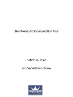
Figure 4-1 shows a picture of the front and rear of a 1924 switch. The top part shows
the front while the bottom part shows the rear. For the top part of the picture, there
is a cut-out of the LEDs on the left-hand side of the switch. The front of the chassis
contains the
MODE
button as well as the LEDs and all but one of the Ethernet ports.
The rear of the chassis has the management connections. You’ll notice that there
is no toggle switch to turn the switch on or off. To turn the switch on, plug one end
of the power cable into the back of the switch and the other into a power outlet. To
turn the switch off, unplug the power cable from either end. Also notice the 10Base5
Ethernet port, which uses a DB-15 AUI interface.
6
Chapter 4: Preparing Network Connections
CertPrs8 / CCNA Cisco Certified Network Associate Study Guide / Deal / 222934-9 / Chapter 4
FIGURE 4-1
A 1924 switch
D:\omh\CertPrs8\934-9\ch04.vp
Monday, August 04, 2003 10:13:49 AM
Color profile: Generic CMYK printer profile
Composite Default screen
Depending on how old your switch is, you’ll have either an RJ-45 (newer) or DB-9
(older) console interface. The DB-9 interface uses a null modem cable for connectivity
to a terminal or terminal emulation device for console access. The RJ-45 interface uses
a rollover cable, discussed later in this chapter. You can also see a very, very small reset
button on the rear of the chassis. You need to use the tip of a pencil or paper clip in
order to press this button. Pressing this button causes the switch to reboot, which is
basically the same as pulling the power cord out of the chassis and putting it back in.
LEDs
The 1900 has four sets of LEDs on the front of its chassis:
SYSTEM
,
RPS
(redundant power
supply), port, and mode LEDs. Table 4-2 shows the status of the system and rps LEDs.
Note that for LEDs that say amber, this is a light orange color. The next section will
cover the rest of the LEDs.
MODE Button
There is an LED above each port on the front of the 1900’s chassis. The meaning of
this LED is dependent upon what mode the LED is set to. You can change the mode by
pressing the
MODE
button on the bottom left-hand side of the front of the chassis, below
the
SYSTEM
and
RPS
LEDs. Right above the
MODE
button are three port-mode LEDs:
STAT
,
UTL
, and
FDUP
. By default, the
STAT
LED is lit: this indicates that the LEDs above
the Ethernet ports refer to the status of the port. Table 4-3 shows the possible LED colors
and descriptions for the various port statuses.
If you push the
MODE
button once, the mode LED will change from
STAT
to
UTIL
.
The
UTIL
LED, when lit, indicates that the LEDs above the Ethernet ports are
Chassis Information
7
CertPrs8 / CCNA Cisco Certified Network Associate Study Guide / Deal / 222934-9 / Chapter 4
LED Color Description
SYSTEM
Green The system is up and operational.
Amber The system experienced a malfunction.
Off The system is powered down.
RPS
Green The RPS is attached and operational.
Amber The RPS is installed, but is not operational. Check the RPS to make
sure that it hasn’t failed.
Flashing amber Both the internal power supply and the external RPS are installed,
but the RPS is providing power.
Off The RPS is not installed.
TABLE 4-2
1900
SYSTEM
and
RPS
LEDs
D:\omh\CertPrs8\934-9\ch04.vp
Monday, August 04, 2003 10:13:49 AM
Color profile: Generic CMYK printer profile
Composite Default screen
functioning as a utilization meter bar. This meter bar reflects the amount of bandwidth
that the switch is currently using on its backplane. The meter readings are different
for a 24-port switch than for a 12-port switch, as is shown in Table 4-4 and Table 4-5.
If you push the
MODE
button again, the LED will change from
UTL
to
FDUP
. When
in
FDUP
mode, the LEDs about the ports represent the duplexing of the ports. If the
LED is green, the port is set to full-duplex. If the port LED is off, the port is set to
half-duplex. If you hit the
MODE
button again, the mode LED will change back to
STAT
. As you can see, the
MODE
button allows you to cycle through the different
mode settings. If the mode LED is either
UTL
or
FDUP
, it will automatically change
back to
STAT
after one minute.
Boot-Up Process and LEDs
Whenever you boot up any of Cisco’s networking products, they will run through
hardware diagnostics called the power-on self test (POST). This is also true with the 1900
switches. When you power up your 1900, initially, all of the port LEDs will be green.
As each self-test in POST is running, a specific LED above an Ethernet port will turn
off (while the others remain green). As the test completes, the LED turns back to green
8
Chapter 4: Preparing Network Connections
CertPrs8 / CCNA Cisco Certified Network Associate Study Guide / Deal / 222934-9 / Chapter 4
LED Color LED Meaning
Green There is a powered-up physical layer connection
to the device attached to the port.
Flashing green There is traffic entering and/or leaving the port.
Flashing green and amber There is an operational problem with the port—
perhaps excessive errors or a connection problem.
Amber The port has been disabled manually (shut down)
or because of a security issue.
Off There is no powered-up physical layer connection
on the port.
TABLE 4-3
Status Mode
and Port LEDs
Port LEDs Lit Up Backplane Bandwidth
1–8 < 6 Mbps
9–16 < 120 Mbps
17–24 < 280 Mbps
TABLE 4-4
Utilization Mode
and Port LEDs
for a 1924
D:\omh\CertPrs8\934-9\ch04.vp
Monday, August 04, 2003 10:13:50 AM
Color profile: Generic CMYK printer profile
Composite Default screen
and another, lower-numbered port LED will go off, signifying that the next POST test is
being performed. Table 4-6 shows the various POST tests that are performed on the 1900.
If a particular self-test fails, then the LED above the port will turn from off to amber
and remain in this state. Normally, if a self-test fails, this is fatal to the switch and the
switch will not boot. If all of the self-tests have been successful, all of the LEDs should
flash green and then turn off. In this state, the
MODE
LED will default to
STAT
.
Chassis Information
9
CertPrs8 / CCNA Cisco Certified Network Associate Study Guide / Deal / 222934-9 / Chapter 4
Port LED Test Performed If the Test Fails
16 ECU DRAM Switch will not boot
15 No self-tests performed
14 No self-tests performed
13 No self-tests performed
12 Forwarding Engine ASIC Switch will not boot
11 Forwarding Engine memory Switch will not boot
10 RAM Switch will not boot
09 ISL ASIC Switch will not boot
08 Port control and status Switch will not boot
07 System timer interrupt Switch will not boot
06 Port address table RAM Switch will not boot
05 Real-time clock Switch will boot
04 Console port Switch will boot
03 Port address table Switch will not boot
02 Switch’s MAC address Switch will not boot
01 Port loopback test A port might not function correctly
TABLE 4-6
POST Tests
Performed
Port LEDs Lit Up Backplane Bandwidth
1–4 < 1.5 Mbps
5–8 < 20 Mbps
9–12 < 120 Mbps
TABLE 4-5
Utilization Mode
and Port LEDs
for a 1912
D:\omh\CertPrs8\934-9\ch04.vp
Monday, August 04, 2003 10:13:50 AM
Color profile: Generic CMYK printer profile
Composite Default screen
Catalyst 2950 Switch
The 2950 series of switches are Cisco’s current desktop and workgroup switching
solution, replacing the 1900 and 2820 switches. The 2950 series of switches come with
two different versions of software: standard and enhanced. This book focuses on the
standard version of software. The enhanced version handles advanced Quality of Service,
telephony, and other features. The other major difference between the different types
of 2950 switch models is the number and types of ports. Table 4-7 compares the 2950
switches and their port types and capacities. The 2950, like the 1900 series, supports
an optional external RPS.
2950 Chassis
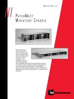
Figure 4-2 shows a picture of the front and rear of a 2950-24 switch. The top part shows
the front, while the bottom part shows the rear. For the top part of the picture, there
is a cut-out of the LEDs on the left-hand side of the switch. The front of the chassis
contains the
MODE
button as well as the LEDs and all of the Ethernet ports.
The rear of the chassis has the management connections. You’ll notice that there
is no toggle switch to turn the switch on or off. To turn the switch on, plug one end
of the power cable into the back of the switch and the other into a power outlet. To
turn the switch off, unplug the power cable from either end.
Unlike the 1900 series, the 2950 doesn’t have a 10Base5 Ethernet port. Also,
the 2950 supports only an RJ-45 console interface, which uses a rollover cable for
connectivity to a terminal or terminal emulation device for console access. The 2950
also doesn’t have a reset button—if you want to reboot the switch, you need to either
10
Chapter 4: Preparing Network Connections
CertPrs8 / CCNA Cisco Certified Network Associate Study Guide / Deal / 222934-9 / Chapter 4
Switch 10/100BaseTX 100BaseFX Gigabit
2950-12 12 0 0
2950-24 24 0 0
2950C-24 24 2 0
2950G-12-EI 12 0 2
2950G-24-EI 24 0 2
2950G-48-EI 48 0 2
2950SX-24 24 0 2
2950T-24 24 0 2
TABLE 4-7
2950 Models
D:\omh\CertPrs8\934-9\ch04.vp
Monday, August 04, 2003 10:13:50 AM
Color profile: Generic CMYK printer profile
Composite Default screen
execute the reload command from the CLI or unplug the power connector from
the switch and then reinsert it.
2950 LEDs and
MODE
Button
Like the 1900, the 2950 has many LEDs on the front of the chassis that you can use to
monitor the switch’s activity and performance. In the top left-hand corner of the front
of the 2950’s chassis are the
SYSTEM
and
RPS
LEDs. The colors of these LEDs and their
meanings are the same as those for the 1900, which were shown in Table 2-2.
Below these two LEDs are four LEDs:
STAT
,
UTIL
,
DUPLX
, and
SPEED
. These LEDs
function similar to the corresponding LEDs on the 1900—they are controlled by the
MODE
button below them. The default mode is
STAT
, which causes the LEDs above
each port to reflect the status of the port. These were explained in Table 2-3.
Pressing the
MODE
button once changes the mode LED from
STAT
to
UTIL
. The
LEDs above each of the ports in this mode reflect the bandwidth utilization of the
backplane of the switch. The LEDs will turn green, acting like a meter bar. If an LED
is amber, this indicates the maximum amount of bandwidth the switch has used since
the switch was booted. This means that the port LEDs to the right of this will be off
Chassis Information
11
CertPrs8 / CCNA Cisco Certified Network Associate Study Guide / Deal / 222934-9 / Chapter 4
FIGURE 4-2
A 2950 switch
D:\omh\CertPrs8\934-9\ch04.vp
Monday, August 04, 2003 10:13:50 AM
Color profile: Generic CMYK printer profile
Composite Default screen