Tài liệu Lab 5.2.3 Building a Basic Routed WAN ppt
Bạn đang xem bản rút gọn của tài liệu. Xem và tải ngay bản đầy đủ của tài liệu tại đây (360.56 KB, 7 trang )
1 - 7 CCNA 1: Networking Basics v 3.0 - Lab 5.2.3 Copyright 2003, Cisco Systems, Inc.
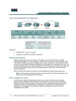
Lab 5.2.3 Building a Basic Routed WAN
Objective
• Create a simple routed wide-area network (WAN) with two PCs, two switches or hubs, and two
routers
• Identify the proper cables to connect a PC and router to each switch
• Identify the proper cables to connect the routers to form a WAN link
• Configure workstation IP address information
• Test connectivity using the ping command
Background / Preparation
This lab focuses on the ability to connect two simple LANs, each consisting of a workstation and a
switch or hub, to form a basic router-to-router WAN. A router is a networking device that can be
used to interconnect LANs which routes packets between different networks using Layer 3 IP
addressing. Routers are typically used to connect the Internet.
In addition to the physical and data link connections, which are layers 1 and 2, the computers and
routers must also be configured with the correct IP network settings, which is Layer 3, so that they
can communicate. Straight-through patch cables are used to connect each PC and router to its
switch or hub. Two special V.35 cables are used to create the simulated WAN link between the
routers.
2 - 7 CCNA 1: Networking Basics v 3.0 - Lab 5.2.3 Copyright 2003, Cisco Systems, Inc.
Note: The two routers need to be preconfigured by the instructor or lab assistant to have the
correct IP addresses on their LAN and WAN interfaces. Router A will provide the clocking
signal as DCE.
Start this lab with the equipment turned off and with cabling disconnected. Work in teams of two with
one person per LAN. The following resources will be required:
• Two workstations with an Ethernet 10/100 NIC installed
• Two Ethernet 10BaseT or Fast Ethernet switches or two hubs
• Two routers with an RJ45 Ethernet or Fast Ethernet interface (or an AUI interface) and at least
one serial interface.
• 10Base-T AUI transceiver (DB15 to RJ45) for a router with an AUI Ethernet interface, which is a
2500 Series
• Four Ethernet straight-through cables for connecting the workstations and routers to the hub or
switch
• One female (DCE) and one male (DTE) V.35 cable for interconnecting the routers
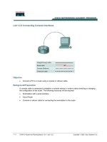
Step 1 Identify and connect the proper Ethernet cable from the PC to the switch
a. The connection between the PC and the switch will be accomplished using a cat 5 or 5e straight-
through patch cable. Attach one end to the NIC and the other end to a port on the switch or hub.
Be sure to examine the cable ends carefully and select only a straight-through cable.
b. Examine the switch or hub.
What is the model number of the switch or hub?
_________________________________________
Step2 Identify the Ethernet or FastEthernet interfaces on the routers
a. Examine the routers.
b. What is the model number of the Router A?
_________________________________________
c. What is the model number of the Router B?
_________________________________________
d. Locate one or more RJ45 connectors on each router labeled “10/100 Ethernet” as shown below.
This identifier may vary depending on the type of router used. A 2500 series router will have an
AUI DB15 Ethernet port labeled “AUI 0”. These will require a 10Base-T transceiver to connect to
the RJ45 cable.
e. Identify the Ethernet ports that could be used for connecting the routers. Record the information
below. Record the AUI port numbers when working with a Cisco 2500 series router.
Router Port Port
3 - 7 CCNA 1: Networking Basics v 3.0 - Lab 5.2.3 Copyright 2003, Cisco Systems, Inc.
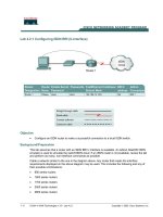
Step 3 Cable the router LAN links
a. Router configuration
The routers should be preconfigured by the instructor or lab assistant so that the Ethernet 0
interface on each router has the proper IP address and subnet mask as indicated in the table
below. This will allow the routers to route packets between local area networks 192.168.1.0 and
192.168.2.0.
Router E0 Interface IP Address Subnet mask
Router – A 192.168.1.1 255.255.255.0
Router – B 192.168.2.1 255.255.255.0
b. Connecting the cables
The connection between the router and the hub or switch will be accomplished using a CAT 5
straight-through patch cable. Locate a patch cable that is long enough to reach from the router to
the hub. Be sure to examine the cable ends carefully and select only straight-through cables.
Connect the Ethernet interface that uses the 0 (zero) designation on the router to a port on the
hub or switch. Also use the 10BASE-T AUI transceiver for the 2500 series routers.
Step 4 Verify the physical Ethernet connections
a. Plug in and turn on the computers, switches/hubs and routers. To verify the connections, insure
that the link lights on the both PC NICs, both switch/hub interfaces and router Ethernet interfaces
are lit. Are all link lights lit?
_____________________
If not, check connections and cable types.
Step 5 Identify the serial interfaces on the router
a. Examine the routers.
b. Identify the serial ports on each router that could be used for connecting the routers to simulate a
WAN link. Record the information below. If there is more than one serial interface, use Interface
0 on each router.
Router Name Router Serial Port Router Serial Port
Router A
Router B
Step 6 Identify and locate the proper V.35 cables
a. Next, inspect the serial cables available in the lab. Depending on the type of router and/or serial
card, the router may have different connectors.
b. Router serial port characteristics
4 - 7 CCNA 1: Networking Basics v 3.0 - Lab 5.2.3 Copyright 2003, Cisco Systems, Inc.
The two most common types are the DB-60 connector and the smart serial. Using the table
below indicate which type routers that are being used.
Router Smart Serial
DB60
RTR
A
RTR
B
c. Simulating the WAN link - DCE / DTE and Clocking
Since this will not be through a live lease line, one of the routers will need to provide the clocking
for the circuit. This is normally provided to each of the routers by a DCE device such as a
CSU/DSU. To provide this clocking signal, one of the routers will need a DCE cable instead of
the normal DTE that is used on the other router. Therefore, the connection between routers
needs to be done using one DCE cable and one DTE cable between routers. A V.35 DCE cable
and a V.35 DTE cable will be used to simulate the WAN connection.
d. V. 35 cable characteristics
The V.35 DCE connector is a large female V.35 (34-pin) connector. The DTE cable has a large
male V.35 connector. The cables are also labeled as DCE or DTE on the router end of the cable.
Use the DCE cable on Router A since it will be providing the clock signal.
DTE
DCE
Step 7 Cable the router WAN link
a. Router configuration
Router A should be preconfigured by the instructor or lab assistant to provide the DCE clock
signal on the Serial 0 interface. The Serial 0 interface on each router should have the proper IP
address and subnet mast as indicated in the table below. The network interconnecting the router
serial interfaces is 192.168.3.0.
5 - 7 CCNA 1: Networking Basics v 3.0 - Lab 5.2.3 Copyright 2003, Cisco Systems, Inc.
Router Clocking S0 Interface IP Address Subnet mask
Router – A DCE 192.168.3.1 255.255.255.0
Router – B DTE 192.168.3.2 255.255.255.0
b. Connecting the cables
The DCE cable will attach to the Serial 0 interface on Router A. The DTE cable should be attached
to the Serial 0 interface on Router B. First make the connection between the two V.35 cables. There
is only one proper way for the cables to fit together. Align the pins on the male cable with the sockets
on the female cables and gently couple them. When they are joined, turn the thumbscrews clock-
wise to secure the connectors.
Make the connection to each of the routers. Holding the connector in one hand, properly orient the
cable connector and the router connecter so that the tapers match. Push the cable connector
partially into the router connector and tighten the thumb screws to fully insert the cable into the
connector.
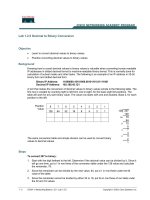
Step 8 Configure Workstation IP settings
Note: Be sure to write down the existing IP settings so that they can be restored at the end
of the lab. These include IP address, subnet mask, default gateway, and DNS servers. If the
workstation is a DHCP client, it is not necessary to record this information.
Access the IP Settings window.
Windows 95 / 98 / ME/ users should do the following:
• Click on Start > Settings > Control Panel and then click the Network icon.
• Select the TCP/IP protocol icon that is associated with the NIC in this PC and click on
Properties.
• Click on the IP Address tab and the Gateway tab.
Windows NT / 2000 users should do the following:
• Click on Start > Settings > Control Panel and then click the Network icon.
• Click on the Protocols tab and select the TCP/IP protocol icon that is associated with the NIC in
this PC.
• Click on Properties and click on Specify an IP address.
Windows XP users should do the following:
• Click on Start > Control Panel and then click the Network Connection icon.
• Select the Local Area Network Connection and click on Change settings of this connection.
See the example below.