Tài liệu Lab 5.2.5 Configuring Frame Relay Subinterfaces pdf
Bạn đang xem bản rút gọn của tài liệu. Xem và tải ngay bản đầy đủ của tài liệu tại đây (214.88 KB, 7 trang )
1 - 7 CCNA 4: WAN Technologies v 3.0 - Lab 5.2.5 Copyright 2003, Cisco Systems, Inc.
Lab 5.2.5 Configuring Frame Relay Subinterfaces
Objective
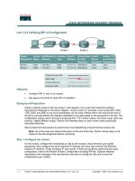
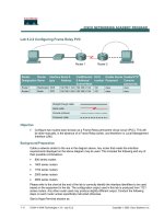
• Configure three routers in a full-mesh Frame Relay network.
Background/Preparation
An Adtran Atlas550 Frame Relay emulator is used to simulate the Frame Relay switch/cloud.
Cable a network similar to the one in the diagram above. Any router that meets the interface requirements
displayed on the above diagram may be used. This includes the following and any of their possible
combinations:
• 800 series routers
• 1600 series routers
• 1700 series routers
• 2500 series routers
• 2600 series routers
Please refer to the chart at the end of the lab to correctly identify the interface identifiers to be used based
on the equipment in the lab. The configuration output used in this lab is produced from 1721 series
2 - 7 CCNA 4: WAN Technologies v 3.0 - Lab 5.2.5 Copyright 2003, Cisco Systems, Inc.
routers. Any other router used may produce slightly different output. Conduct the following steps on each
router unless specifically instructed otherwise.
Start a HyperTerminal session.
Note: Refer to the erase and reload instructions at the end of this lab. Perform those steps on all
routers in this lab assignment before continuing.
Step 1 Configure the routers
Configure the following according to the chart:
• The hostname
• The console
• The virtual terminal
• The enable passwords
• The fastethernet interfaces according to the chart
If problems occur during this configuration, refer to Lab 1.1.4a Configuring NAT.
Step 2 Configure the Serial 0 Interfaces
a. First, the Frame Relay encapsulation type to be used on this link must be defined using the following
commands:
Amsterdam#configure terminal
Amsterdam(config)#interface serial 0
Amsterdam(config-if)#encapsulation frame-relay ietf
Amsterdam(config-if)#frame-relay lmi-type ansi
b. Use a description field to store relevant information, such as the circuit number in case a line fault has
to be reported:
Amsterdam(config-if)#description Circuit #KPN465555
Amsterdam(config-if)#no shutdown
c. The same commands are used to configure the Berlin and Paris routers:
Paris(config)#interface serial 0
Paris(config-if)#encapsulation frame-relay ietf
Paris(config-if)#frame-relay lmi-type ansi
Paris(config-if)#description Circuit #FRT372826
Paris(config-if)#no shutdown
Berlin(config)#interface serial 0
Berlin(config-if)#encapsulation frame-relay ietf
Berlin(config-if)#frame-relay lmi-type ansi
Berlin(config-if)#description Circuit #DTK465866
Berlin(config-if)#no shutdown
3 - 7 CCNA 4: WAN Technologies v 3.0 - Lab 5.2.5 Copyright 2003, Cisco Systems, Inc.
Step 3 Create subinterfaces on the Amsterdam router
For each of the permanent virtual circuits (PVCs), create a subinterface on the serial port. This
subinterface will be a point-to-point configuration. For consistency and future troubleshooting, use the
data-link connection identifier (DLCI) number as the subinterface number. The commands to create a
subinterface are as follows:
Amsterdam(config-if)#interface serial 0.102 point-to-point
Amsterdam(config-if)#description PVC to Paris, DLCI 102, Contact Rick
Voight(+33-1-5534-2234) Circuit #FRT372826
Amsterdam(config-if)#ip address 192.168.4.1 255.255.255.0
Amsterdam(config-if)#frame-relay interface-dlci 102
Amsterdam(config-if)#interface serial 0.103 point-to-point
Amsterdam(config-if)#description PVC to Berlin, DLCI 103, Contact P
Wills(+49- 61 03 / 7 65 72 00) Circuit #DTK465866
Amsterdam(config-if)#ip address 192.168.5.1 255.255.255.0
Amsterdam(config-if)#frame-relay interface-dlci 103
Step 4 Create subinterfaces on the Paris router
To configure the subinterfaces on the Paris router, use the following commands:
Paris(config-if)#interface Serial 0.201 point-to-point
Paris(config-if)#description PVC to Amsterdam, DLCI 201, Contact Peter
Muller (+31 20 623 32 67) Circuit #KPN465555
Paris(config-if)#ip address 192.168.4.2 255.255.255.0
Paris(config-if)#frame-relay interface-dlci 201
Paris(config-if)#interface Serial 0.203 point-to-point
Paris(config-if)#description PVC to Berlin, DLCI 203, Contact Peter Willis
(+49- 61 03 / 7 66 72 00) Circuit #DTK465866
Paris(config-if)#ip address 192.168.6.1 255.255.255.0
Paris(config-if)#frame-relay interface-dlci 203
Step 5 Create subinterfaces on the Berlin router
To configure the subinterfaces on the Berlin router, use the following commands:
Berlin(config-if)#interface Serial 0.301 point-to-point
Berlin(config-if)#description PVC to Amsterdam, DLCI 301, Contact Peter
Muller (+31 20 623 32 67) Circuit #KPN465555
Berlin(config-if)#ip address 192.168.5.2 255.255.255.0
Berlin(config-if)#frame-relay interface-dlci 301
Berlin(config-if)#interface Serial 0.302 point-to-point
Berlin(config-if)#description PVC to Paris, DLCI 302, Contact Rick Voight
(+33-1-5534-2234) Circuit #FRT372826
Berlin(config-if)#ip address 192.168.6.2 255.255.255.0
Berlin(config-if)#frame-relay interface-dlci 302
4 - 7 CCNA 4: WAN Technologies v 3.0 - Lab 5.2.5 Copyright 2003, Cisco Systems, Inc.
Step 6 Configure IGRP routing
To configure the routing protocol Interior Gateway Routing Protocol (IGRP) 100, use the following
configuration syntax:
Amsterdam(config-if)#router igrp 100
Amsterdam(config-router)#network 192.168.1.0
Amsterdam(config-router)#network 192.168.4.0
Amsterdam(config-router)#network 192.168.5.0
Paris(config-if)#router igrp 100
Paris(config-router)#network 192.168.2.0
Paris(config-router)#network 192.168.4.0
Paris(config-router)#network 192.168.6.0
Berlin(config-if)#router igrp 100
Berlin(config-router)#network 192.168.3.0
Berlin(config-router)#network 192.168.5.0
Berlin(config-router)#network 192.168.6.0
Step 7 Verifying Frame Relay PVC
a. On the Amsterdam router, issue the command show frame-relay pvc:
Amsterdam#show frame-relay pvc
b. How many active local PVCs are there?
_____________________________________________
c. What is the interface value?
_____________________________________________________
d. What is the PVC status?
________________________________________________________
e. Which DLCI # is inactive?
_______________________________________________________
f. From this it can be seen that there are three DLCIs defined on this Frame Relay circuit, and only two
of them are in use. This is the way the Adtran 550 emulator has been configured. It is useful output,
as it shows what would be seen if a DLCI is defined on the Frame Relay switch, but not configured on
the router. The other DLCIs, 102 and 103, are ACTIVE and associated with their respective
subinterfaces. It also shows that some packets have actually passed across the PVC.
Step 8 Show the Frame Relay maps
a. Look at the frame relay maps by typing the command show frame-relay map at the privileged
EXEC mode prompt:
Amsterdam#show frame-relay map
b. What is the status of the links?
___________________________________________________
c. The DLCIs are defined as what type?
_______________________________________________
d. Are the DLCIs the same on the Paris router?
_________________________________________
5 - 7 CCNA 4: WAN Technologies v 3.0 - Lab 5.2.5 Copyright 2003, Cisco Systems, Inc.
Step 9 Show LMIs
a. Look at the Local Management Interface (LMI) statistics using the show frame-relay lmi
command:
Amsterdam#show frame-relay lmi
b. Which fields have non-zero counter values?
__________________________________________
c. What is the LMI type?
__________________________________________________________
Step 10 Check routing protocol
a. Use the show ip route command to verify that the PVCs are up and active:
Amsterdam#show ip route
b. Is the routing protocol working?
___________________________________________________
c. If not, troubleshoot the routers configurations.
d. List the IGRP routes
___________________ ___________________ ___________________
Step 11 Verify connectivity
a. Ping the fastethernet interfaces.
b. Were the pings successful?
______________________________________________________
c. If the pings were not successful, troubleshoot the router configurations and repeat this step.
Upon completion of the previous steps, finish the lab by doing the following:
• Logoff by typing exit
• Turn the router off
• Remove and store the cables and adapter