Tài liệu CCIE Practice Scenario Labs doc
Bạn đang xem bản rút gọn của tài liệu. Xem và tải ngay bản đầy đủ của tài liệu tại đây (184.88 KB, 5 trang )
CISCO SYSTEMS TECHNICAL READINESS DOCUMENT
CCIE Practice Scenario Labs
Introduction
This document is designed to be a companion to Volume 1,2,3 and 4. The CCIE
certification is a written test and a lab test. This document will help the student further build
upon their technical skills and configuration skills. The document contains practice CCIE
scenario labs.
Background
These scenarios have been compiled from various sources including current partner CCIEs.
These are not the only scenarios you will be tested with on the CCIE lab exam. They are
designed to give you a flavor for the lab exam. Students are encouraged to use these
scenarios to assist them in devising other scenarios with different physical topologies using
multiprotocol scenarios.
REMEMBER: YOU CAN BE TESTED ON ANY AND ALL TECHNOLGIES ON
THE CCIE LAB EXAM
Prerequisites
The student must also have taken and past the CCIE written test.
CISCO SYSTEMS TECHNICAL READINESS DOCUMENT
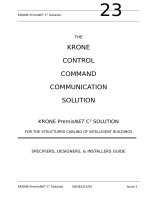
CCIE Practice Lab Scenario 1
NBMA Network
(Frame Relay)
Ring 1
R6
R5
R1
R2
Ring 3
R3
Ring 2
110
101
100
102
Lab 1. Connect Terminal Server (1 hour)
1. Setup routers as shown in the diagram above:
2. Configure a ip host list for a reverse telnet session into each router.
Lab 2. IP (6 hours)
1. Configure the network using network 130.10.x.x
2. Use an 8 bit subnet mask unless otherwise specified
3. At the end of each exercise, verify connectivity between all ports:
4. All ip routes appearing in all routers
5. Ping from any interface to any other interface
Lab 2a
CISCO SYSTEMS TECHNICAL READINESS DOCUMENT
1. Connect R6, R1, and R5 over Frame Relay. Use single subnet over the
frame cloud.
2. Configure OSPF with the cloud in area 0. Configure R2, R3 and R1-R2 serial
to be in area 1.
3. Configure two loopbacks on R6 using subnets that will contain at most 14
host ip addresses. Configure two loopbacks on R5 using subnets that will
contain at most 62 hosts. Summarize the two loopback interfaces on R6 and
R5 such that R1 only sees one route from each.
Lab 2b
1. Remove OSPF configurations from R2, R3 and the serial connection between
R1 and R2. Configure EIGRP on R2, R3 and on the serial connection
between R1 and R2. Redistribute OSPF and EIGRP on R1.
2. Repeat step 1 using IGRP instead of EIGRP.
Lab 2c
1. Filter such that R3 can ping the loopbacks on R5 but not the ethernet. The
route for the ethernet should still be visible.
2. Filter on R2 such that R6, R5, and R1 only see the routes from the token-ring
interface on R3.
3. Remove the filters from R2.
Lab 3. Appletalk (1 hour)
At the end of each exercise, verify connectivity between all ports:
1. All Apple routes/zones appearing in all routers
2. Apple ping from any interface to any other interface
Lab 3a
1. Configure all ports (except loopbacks) for appletalk. Define a zone on each
interface. Define an interface on R3 as Appletalk phase I.
2. Configure EIGRP for R1, R2, and R3.
3. Configure RTMP/ZIP for the NBMA network.
Lab 3b
1. Filter on R2 such that R3 only sees routes and zones from R6.
CISCO SYSTEMS TECHNICAL READINESS DOCUMENT
Lab 3c
1. Remove Appletalk from the serial network between R1 and R2. All zones and
routes should still be seen by all routers running Appletalk.
Lab 4. DECnet (30 minutes)
At the end of each exercise, verify connectivity between all ports
1. Appropriate DEC areas/nodes appearing in all routes
2. DEC ping from any router to any other router
Lab 4a
1. Enable DECnet routing on all routers. Configure R2 and R3 in a separate
DECnet area from the rest of the routers.
Lab 5. IPX (1 hour)
At the end of each exercise, verify connectivity between all ports.
1. Appropriate IPX routes/SAP’s appearing in all routers
2. IPX ping from any interface to any other interface
Lab 5a
1. Configure all ports (including loopbacks) for IPX.
2. ConfigureRIP/SAP on R2, R3, and the serial network between R1 and R2.
3. Configure only EIGRP on R6, R5, and R1’s NBMA network interface.
4. Redistribute on R1.
Lab 5b
1. Configure two static SAPs on R3. Filter on R2 such that R6, R5, and R1 see
only one of theSAPs.
2. Disable IPX across the NBMA network. All routes should still be seen by all
routers running IPX.
3. Change the frequency of RIP updates across the token-ring connection
between R2 and R3 to once every 2 minutes.
Lab 6. Dial-on-demand routing (2 hours)
At the end of each exercise, verify connectivity between all ports:
1. Ping all interfaces using applicable protocols
CISCO SYSTEMS TECHNICAL READINESS DOCUMENT
Lab 6a
1. Configure an ISDN connection between R1 and R2.
2. Disconnect the serial link between R1 and R2.
3. Configure dial-on-demand routing for IP and IPX between R1 and R2. No
broadcast packets should initiate the dialing.
4. Reconnect the serial link between R1 and R2 and shut down the ISDN
interfaces.
Lab 7. DLSW (1 hour)
1. Configure DLSW between Ring1 and Ring 3.
2. Add R1’s ethernet into the DLSW network. Make sure there is connectivity
between all lan interfaces.
Lab 7a
1. Configure a filter that blocks Netbios packets with destination name “Finance”
from leaving Ring 3.
2. Set up a filter that would permit only SNA traffic between the token-rings.
Lab 8. BGP (1 hour)
1. Remove the routing protocol from the serial link between R1 and R2. Create
a BGP autonomous network between these routers. For the AS containing R2
and R3, configure the network using network 140.20.0.0. Redistribute and
aggregate all routes.