Tài liệu Wide Area Networks doc
Bạn đang xem bản rút gọn của tài liệu. Xem và tải ngay bản đầy đủ của tài liệu tại đây (2.17 MB, 82 trang )
Copyright © 2000, Cisco Systems, Inc. 1
© 2000, Cisco Systems, Inc.
Wide Area NetworksWide Area Networks
Copyright © 2000, Cisco Systems, Inc. 2
© 2000, Cisco Systems, Inc. www.cisco.com
Keep All Graphics Inside This Box
econ_0481_09_010.ppt
Section I
Policy / Shaping
Section I
Policy / Shaping
© 2000, Cisco Systems, Inc. www.cisco.com
Copyright © 2000, Cisco Systems, Inc. 3
© 2000, Cisco Systems, Inc. www.cisco.com
Keep All Graphics Inside This Box
econ_0481_09_010.ppt
Objectives
Objectives
Upon completion of this module section, you will be able to
perform the following tasks:
• Describe the difference between policing and shaping
and how each one relates to QoS
• Describe committed access rate (CAR), when to apply
CAR, how to configure CAR
• Describe Modular Quality of Service Command Line
Interface (MQC) policing and how to configure it
• Identify the three types of traffic shaping, their
differences, and how to apply each
The purpose of the lesson is to quickly survey the new policing and traffic shaping
features in Cisco IOS Release 12.1, and to describe the problems they solve.
Copyright © 2000, Cisco Systems, Inc. 4
© 2000, Cisco Systems, Inc. www.cisco.com
Keep All Graphics Inside This Box
econ_0481_09_010.ppt
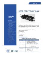
Remote Sites
T1
Central
Site
Frame Relay, ATM
128kbps
256kbps
512kbps
768kbps
T1
Result:
Buffering = Delay or Dropped Packets
Customer Problems to Solve
Customer Problems to Solve
• Central to Remote Site Speed Mismatch
• Remote to Central Site Over-subscription
• Control use of shared LAN, WAN, MAN media
–Multi-Dwelling Unit (MDU)
The slide shows a Frame Relay or ATM network. Pay close attention to the speeds
of the access lines to the remote sites on the left. Suppose each site has a
Committed Information Rate (CIR) close to the access speed with bursting up to
the access bandwidth.
• What happens at the central site if the bottom two sites burst at the same
time?
• What happens at the central site if a server rapidly transmits data for the top
left remote site?
• What happens if the bottom two left sites try to send a large amount of data
to the top left site?
In this section, some of the QoS techniques that help resolves issues such as
theseare examined.
Copyright © 2000, Cisco Systems, Inc. 5
© 2000, Cisco Systems, Inc. www.cisco.com
Keep All Graphics Inside This Box
econ_0481_09_010.ppt
Internet
Policing and traffic shaping occur
within the network to provide congestion
management and control bursts
Policing and traffic shaping occur
within the network to provide congestion
management and control bursts
Network Management
Policing and Shaping
Policing and Shaping
In this module section, policing and traffic shaping are discussed. Both of these
traffic engineering methods occur within the network as indicated by the heavy
ellipse in the slide. They use the already marked Type of Service (ToS) or
Differentiated Services Code Point (DSCP) bits discussed in the previous module.
With policing the rate at which traffic can flow is capped. This is usually done
inbound to control how fast someone sends data.
With shaping, smooth out bursts for a steadier flow of data. Reduced burstiness
helps reduce congestion in a network core.
Copyright © 2000, Cisco Systems, Inc. 6
© 2000, Cisco Systems, Inc. www.cisco.com
Keep All Graphics Inside This Box
econ_0481_09_010.ppt
Policing
Policing
Policing is the QoS component that limits
traffic flow to a configured bit rate:
• With limited bursting capability
• But no buffers, packets above the specified
burst rate are dropped or have their
precedence altered
A policer typically drops traffic.
For example, CARs rate-limiting policer will either drop the packet or rewrite its
IP Precedence, resetting the packet header's ToS bits.
Policing is also available through the MQC.
Copyright © 2000, Cisco Systems, Inc. 7
© 2000, Cisco Systems, Inc. www.cisco.com
Keep All Graphics Inside This Box
econ_0481_09_010.ppt
Shaping
Shaping
Shaping is the QoS feature component
that regulates traffic flow to an average
or peak bit rate:
• With bursting capability
• With buffers, packets that cannot be sent are
queued
A shaper typically delays excess traffic using a buffer, or queuing mechanism, to
hold packets and shape the flow when the data rate of the source is higher than
expected.
For example, Generic Traffic Shaping (GTS) uses a weighted fair queue to delay
packets in order to shape the flow.
Depending on how it is configured, Frame Relay Traffic Shaping (FRTS) uses
either a Priority Queue (PQ), a Custom Queue (CQ), or a first-in, first-out (FIFO)
queue for the same sort of purpose.
Copyright © 2000, Cisco Systems, Inc. 8
© 2000, Cisco Systems, Inc. www.cisco.com
Keep All Graphics Inside This Box
econ_0481_09_010.ppt
Time
Traffic
Time
Traffic Rate
Traffic Policing
Versus Shaping
Traffic Policing
Versus Shaping
Policer
Causes TCP
resends
Oscillation of TCP
windows
Policer can be marker
also (CAR)
Policer on input
interface only
Shaper
Can adapt to network
congestion (FR BECN,
FECN)
Shaping
Traffic
Traffic Rate
Policing
Traffic
Time
Traffic Rate
Traffic
Time
Traffic Rate
This diagram shows the effects of traffic shaping.
Both policing and shaping ensure that traffic does not exceed a (contracted) bandwidth
limit. Policing and Shaping both limit bandwidth but with different traffic impact:
• Policing drops more often, more resends
• Shaping adds variable delay
Traffic shaping smoothes traffic by storing traffic above the configured rate in a queue.
When a packet arrives at the interface for transmission, the following happens:
• If the queue is empty, the arriving packet is processed by the traffic shaper:
– If possible, the traffic shaper sends the packet.
– Otherwise, the packet is placed in the queue.
• If the queue is not empty, the packet is placed in the queue.
When there are packets in the queue, the traffic shaper removes the number of packets it
can send from the queue every time interval.
Additional details on policing and shaping can be found at:
/>polts.htm
Copyright © 2000, Cisco Systems, Inc. 9
© 2000, Cisco Systems, Inc. www.cisco.com
Keep All Graphics Inside This Box
econ_0481_09_010.ppt
Topics
Topics
Policing
• CAR
• MQC
Traffic shaping
Copyright © 2000, Cisco Systems, Inc. 10
© 2000, Cisco Systems, Inc. www.cisco.com
Keep All Graphics Inside This Box
econ_0481_09_010.ppt
Committed Access Rate (CAR)
Committed Access Rate (CAR)
CAR performs three functions:
• Packet classification
• Packet marking—IP Precedence
and QoS group setting
• Manage access bandwidth through rate
limiting (policing)
CARs rate-limiting feature manages a network's access bandwidth policy by ensuring
that traffic falling within specified rate parameters is sent, while dropping packets that
exceed the acceptable amount of traffic or sending them with a different priority. CARs
exceed action is to drop packets.
The rate-limiting function of CAR does the following:
• Allows the control the maximum rate of traffic transmitted or received on an
interface.
• Gives the ability to define Layer 3 aggregate or granular incoming or outgoing
(ingress or egress) bandwidth rate limits and to specify traffic-handling policies
when the traffic either conforms to or exceeds the specified rate limits.
• Uses aggregate bandwidth rate limits to match all of the packets on an interface or
sub-interface.
• Uses granular bandwidth rate limits to match a particular type of traffic based on
precedence, MAC address, or other parameters.
CAR is often configured on interfaces at the edge of a network to limit traffic into or
out of the network.
VIP-distributed CAR is a version of CAR that runs on the Versatile Interface Processor
(VIP). It is supported on the Cisco 7500 routers with a VIP2-40 or greater interface
processor.
Distributed Cisco Express Forwarding (dCEF) switching must be enabled on any
interface that uses VIP-Distributed CAR, even when only output CAR is configured.
Copyright © 2000, Cisco Systems, Inc. 11
© 2000, Cisco Systems, Inc. www.cisco.com
Keep All Graphics Inside This Box
econ_0481_09_010.ppt
VoIP FTPHTTP
FTP
HTTP
VoIP
Gold Class
Silver Class
Bronze Class
Separate “Conform” and
“Exceed” Actions
Policing Engine
VoIP HTTP FTP
CAR
Marking and Policing
CAR
Marking and Policing
• Rule-based engine
• Class of Service (CoS) packet classification (set-ToS) based on
flexible rules
– IP Precedence / IP access list / incoming interface / MAC address
• Rate limiting Functionality
• Generally deployed at the network edge
Once a packet has been measured as conforming to or exceeding a particular rate
limit, the router performs one of the following actions on the packet:
• Transmit—The packet is sent.
• Drop—The packet is discarded.
• Set precedence (or perhaps DSCP bits) and transmit—The IP Precedence
(ToS) bits in the packet header are rewritten. The packet is then sent. Use this
action to either color (set precedence) or recolor (modify existing packet
precedence) the packet.
• Continue—The packet is evaluated using the next rate policy in a chain of rate
limits. If there is not another rate policy, the packet is sent.
Copyright © 2000, Cisco Systems, Inc. 12
© 2000, Cisco Systems, Inc. www.cisco.com
Keep All Graphics Inside This Box
econ_0481_09_010.ppt
Application Hosting
Backbone
3) Invoke QoS policy action
based on edge
classification, for example,
drop low priority via WRED
if burst limit exceeded
1) Packet marking
through IP Precedence
and QoS group settings.
Based on ACL or
inbound interface
2) Apply rate limiting to matching
traffic pattern, for example,
25Kbps of traffic to “Bronze”
San Jose
Ottawa
CAR Bandwidth Management
CAR Bandwidth Management
Today, all the packets on the network look the same, and are thus handled the same, with
each packet getting best-effort service. CAR provides the capability to allow the service
provider or enterprise to specify a policy which determines which packets should be
assigned to which traffic class. The IP header already provides a mechanism to do this,
namely the three precedence bits in the ToS field in the IP header.
CAR can set policies based on information in the IP or TCP header such as IP address,
application port, physical port or sub-interface, and IP protocol to decide how the
precedence bits should be marked or “colored.” Once marked, appropriate treatment can
be given in the backbone to ensure that premium packets get premium service in terms of
bandwidth allocation, delay control, and so on.
CAR can also be used to police precedence bits set externally to the network either by the
customer or by a downstream service provider. Thus the network can decide to either
accept or override external decisions.
CARs purpose is to identify packets of interest for packet classification or rate limiting or
both, matching a specification such as:
1) All traffic
2) IP Precedence
3) MAC address
4) IP access list, standard and extended (slower)
See the following URL for additional information:
/>1/qccar.htm
Copyright © 2000, Cisco Systems, Inc. 13
© 2000, Cisco Systems, Inc. www.cisco.com
Keep All Graphics Inside This Box
econ_0481_09_010.ppt
CAR
Action Policies
CAR
Action Policies
Configurable actions:
• Transmit
• Drop
• Continue (go to the next
rate-limit or police statement in the list)
• Set precedence and transmit (rewrite the IP
Precedence bits and transmit)
• Set precedence and continue (rewrite the IP
Precedence bits and go to the next
rate-limit or police statement in the list)
In Release 11.1 CC the CAR rate limit list is not bounded as to length.
Each CAR rate limit statement is checked sequentially for a match. When a match
is found the token bucket, if there is one, is evaluated.
If the action is a “continue” action, the policer will go to the next rate-limit on the
list to find a subsequent match. If a match is found, the traffic is subjected to the
next applicable rate-limit.
If an end of rate-limit list is encountered without finding a match or “continue”
action, the default behavior is to transmit.
Copyright © 2000, Cisco Systems, Inc. 14
© 2000, Cisco Systems, Inc. www.cisco.com
Keep All Graphics Inside This Box
econ_0481_09_010.ppt
MQC Policing Actions
MQC Policing Actions
The available actions are different than
with CAR:
• transmit
• drop
• set-prec-transmit value
• set-dscp-transmit value
• set-qos-transmit value
The slide lists the actions available with MQC police. They are similar to, but
different than, the CAR action options.
For additional information see:
/>7183
Copyright © 2000, Cisco Systems, Inc. 15
© 2000, Cisco Systems, Inc. www.cisco.com
Keep All Graphics Inside This Box
econ_0481_09_010.ppt
MQC Policing Actions
MQC Policing Actions
The available actions are different than
with CAR:
• transmit
• drop
• set-prec-transmit value
• set-dscp-transmit value
• set-qos-transmit value
The slide lists the actions available with MQC police. They are similar to, but
different than, the CAR action options.
For additional information see:
/>7183
Copyright © 2000, Cisco Systems, Inc. 16
© 2000, Cisco Systems, Inc. www.cisco.com
Keep All Graphics Inside This Box
econ_0481_09_010.ppt
Additional Policy Map Policing
and Shaping Options
Additional Policy Map Policing
and Shaping Options
Policing policy-map options:
• police bps conform action exceed action
• set ip precedence number
• set qos-group number
Distributed Traffic Shaping (DTS)
policy-map options:
• shape [average | peak] meanrate [burst-size
[excess-burst-size]]
• shape fecn-adapt
• shape adaptive
ATM CLP policy-map options:
• set atm-clp
The commands shown are some of the other options to use in the MQC policy
map. They are listed here so all options can be referenced back to this location in
the module section.
DTS commands will be covered in more detail later in this module. To turn on
DTS, enter any of the shape commands.
Copyright © 2000, Cisco Systems, Inc. 17
© 2000, Cisco Systems, Inc. www.cisco.com
Keep All Graphics Inside This Box
econ_0481_09_010.ppt
Additional Policy Map
Queuing Options
Additional Policy Map
Queuing Options
WRED policy-map options:
• random-detect precedence precedence min-threshold
max-threshold mark-prob-denominator
• random-detect
• random-detect exponential-weighting-constant
exponent
LLQ policy-map options:
• priority bandwidth
CBWFQ policy-map options:
• bandwidth kbps
• queue-limit number-of-packets
There are other options in the MQC policy map. The options shown in the slide
invoke queuing methods (covered in more detail in the Queuing and Scheduling
module).
For example, to turn on WRED within a policy map, use any of the
random-detect commands. To reserve a minimum bandwidth with CBWFQ, enter
the bandwidth command.
Copyright © 2000, Cisco Systems, Inc. 18
© 2000, Cisco Systems, Inc. www.cisco.com
Keep All Graphics Inside This Box
econ_0481_09_010.ppt
Topics
Topics
Policing
Traffic shaping
• Token bucket theory
• Generic Traffic Shaping (GTS)
• Distributed Traffic Shaping (DTS)
• Frame-Relay Traffic Shaping (FRTS)
Copyright © 2000, Cisco Systems, Inc. 19
© 2000, Cisco Systems, Inc. www.cisco.com
Keep All Graphics Inside This Box
econ_0481_09_010.ppt
• LAN traffic tends to be bursty and bursty traffic
is the root of all evil…
• Shaping is highly beneficial if downstream
device is policing
–Avoids the “instantaneous congestion”
–Space the traffic to conform to traffic contract
• Packet bursts are queued instead of being
dropped, quickly training TCP sources to send at
the desired rate
• Resulting packet stream is “smoothed” and net
throughput for bursty traffic is higher
Why Traffic Shaping?
Why Traffic Shaping?
The slide lists some of the reasons for Traffic Shaping.
Copyright © 2000, Cisco Systems, Inc. 20
© 2000, Cisco Systems, Inc. www.cisco.com
Keep All Graphics Inside This Box
econ_0481_09_010.ppt
Token Bucket
Bc token-bits
are added every Tc
The packets are sent at access
speed as long as there are enough
token bits
Bc + Be: is the maximum
number of token bits that
can be stored
At t=0, bucket is full!
Tc=Bc/CIR
Over any integral multiple of Tc, the average bit rate of the interface will
not exceed the mean bit rate. The bit rate may, however, be arbitrarily fast
at any time t during this period, upper bound being the access speed.
Over any integral multiple of Tc, the average bit rate of the interface will
not exceed the mean bit rate. The bit rate may, however, be arbitrarily fast
at any time t during this period, upper bound being the access speed.
In the token bucket metaphor, tokens are put into the bucket at a certain rate, Burst
Capacity (Bc) tokens every Time Interval Constant (Tc) seconds. The bucket itself has
a specified capacity. If the bucket fills to capacity (Bc + Excess Burst Capacity (Be)),
newly arriving tokens are discarded. Each token is permission for the source to send a
certain number of bits into the network. To send a packet, the regulator must remove
from the bucket a number of tokens equal in representation to the packet size.
If not enough tokens are in the bucket to send a packet, the packet either waits until the
bucket has enough tokens or the packet is discarded. If the bucket is already full of
tokens, incoming tokens overflow and are not available to future packets. Thus, at any
time, the largest burst a source can send into the network is roughly proportional to the
size of the bucket.
Note that the token bucket mechanism used for traffic shaping has both a token bucket
and a data buffer, or queue; if it did not have a data buffer, it would be a policer. For
traffic shaping, packets that arrive that cannot be sent immediately are delayed in the
data buffer.
For traffic shaping, a token bucket permits burstiness but bounds it. It guarantees that
the burstiness is bounded so that the flow will never send faster than the token bucket's
capacity plus the time interval divided by the established rate at which tokens are
placed in the bucket. It also guarantees that the long-term transmission rate will not
exceed the established rate at which tokens are placed in the bucket.
Bc is known as burst capacity. Be is excess burst capacity. Tc is the time interval
constant. CIR is the Committed Information Rate. All these terms are from Frame-
Relay.
Copyright © 2000, Cisco Systems, Inc. 21
© 2000, Cisco Systems, Inc. www.cisco.com
Keep All Graphics Inside This Box
econ_0481_09_010.ppt
Token Bucket with Class-Based
Weighted Fair Queuing
Initialization:
• Token bucket = Bc+Be
At each Tc:
• Token bucket = min (token bucket + Bc, Bc+Be)
In operation:
• While (token bucket is not empty):
–De-queue traffic from Weighted Fair Queuing
(WFQ)or traffic arrives (if WFQ empty)
–If token bucket is not empty:
• Token bucket = token bucket less message size
• Forward the traffic
–Else: fair queue the traffic
A token bucket is a formal definition of a rate of transfer. It has three components:
a burst size, a mean rate, and a time interval (Tc). Although the mean rate is
generally represented as bits per second, any two values may be derived from the
third:
• Mean rate—Also called the committed information rate (CIR), it specifies how
much data can be sent or forwarded per unit time on average.
• Burst size—Also called the Committed Burst (Bc) size, it specifies in bits per
burst how much can be sent within a given unit of time to prevent scheduling
concerns.
• Time interval—Also called the measurement interval, it specifies the time
quantum in seconds per burst.
By definition, over any integral multiple of the interval, the bit rate of the interface
will not exceed the mean rate. The bit rate may, however, be arbitrarily fast within
the interval.
Copyright © 2000, Cisco Systems, Inc. 22
© 2000, Cisco Systems, Inc. www.cisco.com
Keep All Graphics Inside This Box
econ_0481_09_010.ppt
Transmit
Queue
Output
Line
Traffic
Destined
for
Interface
Classification by:
Extended Access
List Functionality
“Leaky
Bucket”
Shaping
Configured
Queuing
(WFQ,
PQ, and so on)
Match
No Match
Classify
(Generic) Traffic Shaping
(Generic) Traffic Shaping
Traffic shaping allows the control of traffic going out an interface in order to match its flow to
the speed of the remote, target interface and to ensure that the traffic conforms to policies
contracted for it. Thus, traffic adhering to a particular profile can be shaped to meet
downstream requirements, thereby eliminating bottlenecks in topologies with
data-rate mismatches.
The primary reasons traffic shaping should be used are to control access to available
bandwidth, to ensure that traffic conforms to the policies established for it, and to regulate the
flow of traffic in order to avoid congestion that can occur whenthe sent traffic exceeds the
access speed of its remote, target interface.
Traffic shaping limits the rate of transmission of data. Limit the data transfer to one of the
following:
• A specific configured rate
• A derived rate based on the level of congestion
Generic Traffic Shaping (GTS) shapes traffic by reducing outbound traffic flow to avoid
congestion by constraining traffic to a particular bit rate using the token bucket mechanism.
GTS applies on a per-interface basis and can use access lists to select the traffic to shape. It
works with a variety of Layer 2 technologies, including Frame Relay, ATM, Switched
Multimegabit Data Service (SMDS), and Ethernet.
On a Frame Relaysubinterface, GTS can be set up to adapt dynamically to available
bandwidth by integrating Backward Explicit Congestion Notification (BECN) signals, or set
up simply to shape to a pre-specified rate. GTS can also be configured on an ATM AIP model
interface to respond to Resource Reservation Protocol (RSVP) signaled over statically
configured ATM permanent virtual circuits (PVCs).
Copyright © 2000, Cisco Systems, Inc. 23
© 2000, Cisco Systems, Inc. www.cisco.com
Keep All Graphics Inside This Box
econ_0481_09_010.ppt
Generic Traffic Shaping
Generic Traffic Shaping
Applies to:
• Interface, sub-interface, or traffic selected by
access list
• Not available on dial/ISDN interfaces, nor with flow
switching. Use DTS with Versatile Interface
Processor (VIP) cards.
If within threshold:
• Simply forwards traffic
If not within threshold:
• Queues using WFQ-like queue on sub-interface
GTS is supported on most media and encapsulation types on the router. GTS can
also be applied to a specific access list on an interface.
Use DTS (covered in later slides) with the VIP cards.
Copyright © 2000, Cisco Systems, Inc. 24
© 2000, Cisco Systems, Inc. www.cisco.com
Keep All Graphics Inside This Box
econ_0481_09_010.ppt
Transmit
Queue
Output
Line
Traffic
Destined
for Interface
Queueing
Match
No Match
Distributed
Traffic Shaping
Distributed
Traffic Shaping
Enforces a maximum transmit rate
Temporarily reduces transmit rate when signaled by Frame Relay (FR)
Backward Explicit Congestion Notification (BECN) bits set in incoming
frames
Shapes up to 200 FR Virtual Channels (VCs) at OC-3 rates with average
size packets on a VIP2-50
Released in 12.0(4)XE, 12.0(7)S
Distributed Traffic Shaping (DTS) benefits:
• Offloads traffic shaping from the route switch processor (RSP) to the Versatile
Interface Processor (VIP).
• Supports up to 200 shape queues per VIP, supporting up to OC-3 rates when the
average packet size is 250 bytes or greater and when using a VIP2-50 or better with 8
MB of SRAM. Line rates below T3 are supported with a
VIP2-40.
The limitations are:
• Only IP traffic can be shaped
• dCEF must be enabled
• FastEtherChannel, Tunnel, VLAN and ISDN / Dialer interfaces are not supported
For additional information see:
/>120xe/120xe5/dts.htm
Copyright © 2000, Cisco Systems, Inc. 25
© 2000, Cisco Systems, Inc. www.cisco.com
Keep All Graphics Inside This Box
econ_0481_09_010.ppt
Frame-Relay Traffic Shaping
Frame-Relay Traffic Shaping
• Rate enforcement on a per-VC basis
–Peak rate for outbound traffic can be set to
match CIR or another value
• Dynamic traffic throttling on a per-VC basis
–When BECN packets indicate congestion on the
network, outbound traffic rate automatically
stepped down
• Enhanced queuing support on a per-VC basis
–Custom queuing or priority queuing can be
configured for individual VCs
• Can use different VCs for different types of traffic
FRTS provides these capabilities:
• Rate enforcement on a per-VC basis—the peak rate for outbound traffic. The value can be
set to match CIR or another value.
• Dynamic traffic throttling on a per-VC basis—When BECN packets indicate congestion on
the network, the outbound traffic rate is automatically stepped down; when congestion
eases, the outbound traffic rate is increased. This feature is enabled by default.
• Enhanced queuing support on a per-VC basis—Either custom queuing or priority queuing
can be configured for individual VCs.
By defining separate VCs for different types of traffic and specifying queuing and an outbound
traffic rate for each VC, bandwidth for each type of traffic is guarenteed. By specifying
different traffic rates for different VCs over the same line, virtual time-division multiplexing is
performed. By throttling outbound traffic from high-speed lines in central offices to lower-
speed lines in remote locations, congestion and data loss in the network is eased. Enhanced
queuing also prevents congestion-caused data loss.
It is possibleto enable ForeSight congestion management as well. When a Cisco router receives
a ForeSight message indicating that certain data-link connection identifiers (DLCIs) are
experiencing congestion, the Cisco router reacts by activating its traffic shaping function to
slow down the output rate. The router reacts as it would if it were to detect the congestion by
receiving a packet with the BECN bit set.
For additional information see:
/>