Tài liệu Guide Block – 3-D Stress Analysis Pro/ENGINEER and Pro/MECHANICA docx
Bạn đang xem bản rút gọn của tài liệu. Xem và tải ngay bản đầy đủ của tài liệu tại đây (1.74 MB, 32 trang )
1
ME-430 INTRODUCTION TO COMPUTER AIDED DESIGN
Guide Block – 3-D Stress Analysis
Pro/ENGINEER and Pro/MECHANICA
By: Dr. Herli Surjanhata
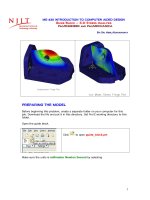
PREPARING THE MODEL
Before beginning this problem, create a separate folder on your computer for this
job. Download the file and put it in this directory. Set Pro/E working directory to this
folder.
Open the guide block.
Click
to open guide_block.prt
Make sure the units is millimeter Newton Second by selecting
2
Edit -> Setup -> Units
Click Close in the Units Manager dialog
box.
Done.
The part to be analyzed is shown below:
Assign steel material in part mode – the material will be carried over for structural or
thermal analysis.
From Edit pull-down menu, select Setup.
3
Select Material.
The Materials dialog box appears.
Pick steel.mtl on
the left column, and
click
to move it
to Materials in
Model box.
Double STEEL or
click
to edit the
current material.
4
Be sure the Units are in millimeter-
Newton-second (mmNs) as shown in
the dialog box located on the left.
Click OK.
5
Click on Thermal tab,
and the units are in
mmNs as shown in the
figure on the left.
OK.
6
OK to close
the
Materials
dialog box.
ENTER Pro/MECHANICA STRUCTURE AND ASSIGN
MATERIAL PROPERTIES, DEFINE LOADS, AND APPLY
CONSTRAINTS
Applications -> Mechanica
7
Make sure the units are
correct.
Click Continue.
Click OK to accept Structure Mode.
Select
to assign the selected material to
the plate model.
The Material Assignment dialog box appears.
8
Be sure that STEEL is display under
Material box.
Click OK to close the Material
Assignment dialog box.
Apply 890 Newtons (200 lbf) in the negative Z-direction on the inner surface of the
hole as shown below.
Apply the second
load of 890 N to
this surface.
9
Click
.
Click the inner cylindrical surface of the hole mentioned above.
Click OK.
Enter the information as shown below.
10
Enter -890 N
force for Z-
component.
Click Preview.
OK.
Create fixed constraints to the bottom and outer left surface of the guide block.
Click
.
Pick the surfaces as shown below for fixed constraint. Be sure that translation X- , Y-
and Z-direction is fixed. Keep the default setting (fixed) for the rotational
constraints.
Note that for 3-D solid elements, there are only three translational constraints per
node. Rotational constraints have no effect in the computation.
11
Click OK on the Select box to accept the
Click OK to close the
Constraint dialog box.
12
DEFINE AND RUN THE ANALYSIS
Mechanica's automated process for generating geometric elements on a model.
AutoGEM generates elements that comply with all element creation rules and that
provide accurate results when Mechanica analyzes your model.
To see how the geometric elements on a guide block,
Click
.
The AutoGEM dialog box
appears.
Click on
button.
AutoGEM generates 402 Tetrahedral elements for the model.