Tài liệu Computer-Aided.Design.Engineering.and.Manufacturing P2 pptx
Bạn đang xem bản rút gọn của tài liệu. Xem và tải ngay bản đầy đủ của tài liệu tại đây (1.71 MB, 68 trang )
© 2001 by CRC Press LLC
2
Computer-Integrated
Assembly for Cost
Effective Developments
2.1 Introduction
2.2 Assembly in Intelligent Manufacturing
Market-Driven Trends in Factory Automation • Cost
Effecti veness by Means of Fle xibility • The T echnology of the
Assembly P rocess
2.3 Effectiveness Through Flexibility Issues
Assessment of the Flexibility Requirements • Decision Supports
and Simulation • Example Developments
2.4 Reconfigurable Set-Ups Assembly Facilities
Modular Assembly Transfer Lines • Modularity of Assembly
Lines with Buffers and By-Passes
2.5 High-Versatility Self-Fixturing Facilities
Robot-Operated Assembling Set-Ups • Assembling by
Integrated Control-and-Management
2.6 Concluding Comments
• Off-Process Setting of a Customer-Driven Mass Production
Assembly Facility • Exploiting Recovery Flexibility with
Adaptive Modular Assembly Facilities • Programming Optimal
Assembly for One-of-a-Kind Products •
2.7 Acknowledgments
2.1 Introduction
For many manufacturing enterprises, assembly is an important portion of the final costs. Effectiveness
was traditionally hunted for by reducing complex schedules into unit tasks (scientific work organization)
and by enabling sequential assembly lines (vertical flow-shop). The approach leads to the highest pro-
ductivity, and it is prised for mass production. Flow-lines and fixed schedules, however, require amorti-
sation plans based on steady programmes on duty horizons corresponding to product volumes exceeding
some minimal threshold. Market saturation and trade instability look for quick updating of the offered
items, properly adapted to wider classes of buyers’ needs, possibly, down to the limit situation of one-
of-a-kind customised quality. Worldwide enterprises looking for purchasers’ oriented supply are, thus,
concerned by time-varying artefacts; extended mixes of items have to be processed in parallel and
delivered with short time-to-market.
The emphasis toward customised quality, product variety, frequently up-dated offers, quick delivery dates,
etc. needs a new approach to effectiveness, exploiting knowledge-intensive set-ups, by schedules complexity
preservation (intelligent work organization) and robotised assembly cells (distributed versatility job-shop).
Rinaldo C. Michelini
University of Genova
Gabriella M. Acaccia
University of Genova
Massimo Callegari
University of Genova
Rezia M. Molfino
University of Genova
Roberto P. Razzoli
University of Genova
© 2001 by CRC Press LLC
The return on investments deals with leanness, namely on checking each addition or modification on
its actual usefulness to increase item’s quality; and with economy of scope, namely on carefully monitoring
aims and tasks on their ability of granting a positive value-chain, while avoiding unnecessary accom-
plishments and useless equipments.
These new trends move to intelligent manufacturing set-ups, supporting: recovery flexibility, as option
instead of set-apart resources; tactical flexibility, to approach optimal schedules assembly process; and
strategic flexibility, for processing variable product mixes. Computer-integrated assembly becomes a cost
effective opportunity, whether exploited to draw out actual benefits from the technological versatility of
the new resources. Different tracks are considered by the present chapter, namely:
• modularity, to make possible the setting and the resetting of the assembly facility with due account
of artefacts evolution, by the off-process management of versatility; and
• robotics, to enable the functional versatility so that several product mixes are processed together,
under supervised standard testing operations according to total quality.
The two techniques are each other subsidiary, have different application range, and will be discussed in the
following, distinguishing the levels of productivity and of flexibility that each time are needed; sample cases
are used for explanatory purposes. Computer-integrated assembly is a relevant aid to fully exploit flexible
automation by enabling the process-driven adaptivity, once the visibility on every relevant quantity affecting
the processing progression is provided and the transparency of the current decision logic is acknowledged.
Such visibility is the preliminary requirement to enable the economy of scope and can actually be reached
by expanding the factory automation software with inclusion of proper expert simulation codes.
The present chapter is organised as follows:
• a section recalls the basic options of intelligent manufacturing to support effective assembly
processes; namely: the market-driven trends in factory automation, towards computer-integrated
assembly, from scientific job allotment to intelligent task assessment; the options of flexibility for
achieving cost effective issues; and the basic technologies of the assembly process, from product-
oriented assembly lines endowed with special purpose equipment, to operation-oriented func-
tional units based on modular layout or built with robot technology;
• a section considers, at the shop floor level, the characterising features to maximise the return on
investments in flexible automation, with focus on assembly problems; i.e., the basic references for
evaluating flexibility effects, from the analysis of characteristic features to judgmental hints for
the setting of the flexibility figures; the decision tools, supporting the choice of the efficiency
setting/fitting figures, exploiting computer-simulation as consultation aid and process-driven gov-
ern as controller-manager of shop floor operations;
• a section presents cost effective issues in computer-integrated assembly for situations requiring
mass production with sudden switching to new artefacts within short time-to-market terms;
namely: the off-process setting of versatility by reconfigurable modular facilities; and the adaptive
fitting (recovery flexibility) of buffered modular assembly facilities with (limited) physical
resources redundancy; and
• a section presents robot assembly facilities, aimed at exploiting the options of flexibility for
customers-driven artefacts; in particular: the on-process setting (strategic flexibility) of robotised
assembly facilities; and the efficient fitting (tactical flexibility) by integration of control and
management; both situations characterised by the functional redundancy of the knowledge inten-
sive solutions provided by intelligent manufacturing.
The example cases of sections 2.4 and 2.5 have been developed by the Industrial Robot Design Research
Group at the University of Genova, Italy, in front of diversified industrial applications at shop floor
level, aiming at govern for flexibility issues, according to the basic ideas summarised in sections 2.2
and 2.3.
© 2001 by CRC Press LLC
2.2 Assembly in Intelligent Manufacturing
Efficient manufacturing of industrial artefacts is conditioned by assembly. Product and process reengi-
neering is positively concerned by setting up cost effective facilities. The return on investment is, however,
a critical issue; to obtain the right layout, the effectiveness of the assembly section has to be assessed
against actual potentialities. The study needs, in general, consider the entire enterprise’s organization,
from the design to the selling of the artefacts and the degree of automation in both material and data
processing has to be acknowledged. At the front-end level one typically deals with:
•fixed assembly stands: the components (suitably assorted and fed) are joined to the (principal)
workpieces at properly fixtured stations by, typically, job-shop logistic; and
• transfer assembly lines: the (main) workpieces are transferred by flow shop logistic (with convey-
ors, belts, etc.) and sequentially joined to the (concurrently fed) parts.
Intermediate solutions, aiming at best compromising effectiveness and adaptivity are, as well, used, e.g.,
• cell shops, performing group technology subassemblies by means of segmented carousels inter-
connected by adaptive dispatching; and
• transfer sections, joining varying mixes (for adaptive processing, job enrichment, etc.) and
enabling several assembly cycles through parts rerouting.
Performance depends on organization and equipment. Productivity (assessed as nominal net production
on the reference time horizon) actually reaches the highest figures with flow shop and transfer assembly,
based on specially fixtured units (readily adapted to fixed automation) aiming at low cost mass production.
Flexibility (related to the property of modifying process abilities to accept varying product mixes) requires
technological versatility; job-shop organization with general purpose workstations is prised, in connection
to robotics, for on-process and on-line adaptivity.
The emphasis toward product variety, constant quality, higher reliability, frequently updated design,
shorter time-to-market, and the likes, forces concurrent enterprise approach, aiming at integrated solu-
tions, from design and development to assembly and delivering stages. Computer integration is the main
factor in simultaneously achieving the said goals by knowledge intensive set-ups. Thus, special attention
is, for instance, reserved to:
• assembly planning [BAL91], [BOO82], [DeW88], [DEF89], [HEN90], [HoL91], [HoS89],
[KoL87], [LeG85], [MAT90], [Mul87], [RoL87], [Wol90];
• design for assembly [AND83], [Bjo89], [BoD84], [BoA92], [Hoe89], [NeW78], [TUR87]; and
• similar options and methods, improving the exploitation of process-embedded knowledge.
Conversely, the layout of the assembly equipment lags behind in flexible automation; as a result, on the
final products the related costs percentually appear to increase. For several applications, indeed, robotics
in assembly provides meagre benefits, since:
• robots magnify the operation-driven constraints of dedicated equipment (fixtures, jigs, grippers,
feeders, etc.) and require a considerable amount of propriety software; as a result, side costs are
four to five times the robot cost; and
• manipulation architecture supports poorly optimised motion for any particular task; even if
sophisticated path planning and dynamics shaping options are provided, the duty-cycle time and
position accuracy are worse than the ones of dedicated units.
An alternative suggests that assembly equipment, built from modular units has to be considered
[ACA96a], [Dre82], [GIU91], [MIL93], [Rog93], [TaA81]:
• productivity preserves the figures of special purpose assembly lines;
• reuse of the selected fixed assets into differently configured layouts makes possible amortisation
plans based on sequences of product mixes.
© 2001 by CRC Press LLC
The modular approach presumes the interfaces consistency based on mechanical and electronic standards.
Then, work cycles are analysed into sets of process primitives having each function performed by a
modular unit. The flexibility is managed off-process by reconfiguring the facility as soon as the plans for
the mass production of new artefacts are fixed. The opportunity will be considered and example appli-
cations are recalled in section 1.4, as issues leading to mass production, while supporting short time-to-
market for new artefacts by means of reconfigurability.
Market-Driven Trends in Factory Automation
The availability on the market of comparable offers requires continuous adaptation of current delivery
to users’ satisfaction, to win new buyers and preserve/expand the trading position of the enterprise. The
course turns to become more relevant as the number of specifications is increased to better adapt the
products to lifecycle standards on safety, anti-pollution, etc. or on recycling and dismantling rules
according to prescriptions aiming at sustainable development promulgated by every industrialised coun-
try [AlJ93], [AlL95], [BoA92], [Eba94], [JOV93], [SEL94], [Wie89], [ZUS94]. Effectiveness is dealt by
balanced and integrated views: customers’ responsiveness, simultaneous product-and-process design,
productive decentralisation for technology adaptivity, and the likes. Each offered artefact is, thereafter,
endowed by quality ranges attributes covering multitudes of users’ requests. Leaving up the mass pro-
duction aims, the actual trend is to propose (once again after handicrafts time) one-of-a-kind products
purposely adapted to individual whims with, however, quality figures granted by standard tolerances, as
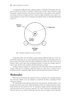
compared to craftworks, Figure 2.1.
Customised artefact quality is consistent with intelligent manufacturing by means of flexible speciali-
sation. Assembly is a critical step; on-line manual operators are common practice when product variability
makes uneasy the facing of changing tasks with high productivity levels. Fully robotised assembly cells
FIGURE 2.1
Trends in market-driven and technology-pushed manufacturing.
Craft
manufacturing
Mass
manufacturing
Customised
manufacturing
Enterprise
return
economy
of skill
economy
of scale
economy
of scope
Work
organisation
master to
apprentice
indenture
scientific
job-allotment
intelligent
task assessment
Technical
specification
design while
manufacturing
off-process
optimal
assessment
simultaneous
product/process
design
Decision
structure
craftsmen
commitment
hierarchical
specialisation
decentralised
responsibility
Motivation
style
individual
creativity
division of
competencies
collaborative
reward
Knowledge
features
non replaceable
personal
contribution
addition of
sectorialised
team work
distributed
cooperative
processing
© 2001 by CRC Press LLC
are, indeed, endowed by extended versatility so that the mix of items jointly processed can be quite large,
but productivity is far from the capability of special purpose assembly facilities. For mass delivery, fixed
automation solutions are, therefore, preferred; the switching to new sets of artefacts cannot be done,
unless the different special purpose devices, properly matching the requested changes, are enabled. The
compression of the time-to-market is sought by simultaneous engineering, namely, by developing prod-
ucts (with design-for-assembly, etc. rules) and processes (with modular configurability or function
programmability).
The ameliorations have been related to the automatic preparation of the assembly sequences [ArG88],
[Bon90], [Boo87], [JIA88], [Koj90], [MIC88], [Tip69], [WAR87] with attention focused on the process
modelling, aiming at plant fitting for granting the visibility of every relevant effect. Formal descriptions
have been likely proposed to design the assembly facilities [ACA96B], [ArG88], [Hoe89], [LeG85],
[Moi88], [ONO93], [ONO94b], [SEK83], [Van90], [WIE91] liable to be translated into functional
models. The computer integration is a powerful contrivance; centrality, however, shall be left to the
manufacturing flow, according to requirements of leanness, which say that non-necessary options are
directly (since not fully exploited) and indirectly (because redundant accomplishment) nuisances.
Summing up, important improvements are expected from the integrated control and management of
the processing operations [ACA88c], [ACA89c], [ACA92b], [MIC92b], [MIC94d], with account of flex-
ibility of the physical (the set-up) and the logical (the fit-out) resources. One should look for:
• the effective set-up of assembly sections, tailored to product mixes included by the enterprise
strategic planning;
• the proper fit-out of assembly schedules, adapted to production agendas within the enterprise
tactical planning.
Off-process and on-process adaptivity, Figure 2.2, happens to become a market-driven request; it has to
be tackled over at the proper level:
• setting is concerned by the structural frames, Components, facility
-
configuration
and control:
CFC the set-up of CFC frames presents as everlasting activity; choices provide reference for
identifying current process set-ups all along the life of the facility; and
FIGURE 2.2
Flexibility setting/fitting by controllers/managers.
© 2001 by CRC Press LLC
•fitting deals with information options of the behavioural frames, Monitoring, decision-manifold
and management: MDM the MDM frames, by acknowledging the plant operational states and
functional trends, offer data for the on-process improvement of the efficiency.
Technical Analysis of the Return on Investments
Leanness is suitably related to the monitoring of the value added to products by each investment into
new physical or logical resources; computer-integrated assembly looks for cost effective set-ups aiming
at economy of scope by means of a knowledge intensive frame, purposely restricted to a series of rules,
such as:
• to extend product mix variability to agree with larger amounts of consumers’ wishes;
• to avoid investment in special rigs and exploit robotisation for diversified products;
• to limit inventory and enable adaptive, bottom-up, just-in-time schedules;
• to suppress redundancies and set-apart resources and instead apply recovery flexibility;
• to abolish not strictly necessary functions and use decentralised responsibility;
• to exclude sectorialisation of competencies to solve problems where they arise;
• to enhance customers’ driven responsiveness by minimal time-to-market; and
• to exploit involvement, for improving products and processes by shared interest.
The different situations asserting economical returns encompass:
• the exploitation of wide-versatility facilities, assuring simultaneous manufacturing of extended
mixes of products, conveniently distributed within the work-shifts;
• the use of system integrators granting one-of-a-kind customised products delivery, by incorpora-
tion of parts or subgroups provided by specialised suppliers;
• the resort to modular assembly facilities, with by-passes and buffers between special purpose units
to perform the adaptive scheduling of moderately varying delivery; and
• the establishment of multiple reconfigurability lines, joined to the concurrent design of products
and processes, to reach step-wise tracking of customers’ satisfaction.
The presetting of the economically effective solutions has been investigated from several stand-points
[ACA89F], [ACA95], [Beh86], [Eve93], [Gus84], [Tan83], [TOB93], [WaW82]. The rentability of the
(off-process) setting and of the (on-process) fitting for govern for flexibility issues, is, mainly, assessed
by computer simulation. The choice of the appropriate set-ups refers to a few factors:
• investment costs, with amortisation plans within the production programmes;
• productivity performances, to grant technical specifications and trade goals;
• delivery figures (or time-to-market), according to customers’ expectation; and
• quality (fitness for purposes and conformance to specifications).
Time-to-market and artefact quality are important factors for enterprises aiming at remaining, or becom-
ing, worldwide competitors. With markets globalisation, a factory cannot be sure to propagate its pro-
tected trade segmentation; short delivering with customer-driven quality is therefore becoming a critical
request [Beh86], [Cuc89], [Lil66], [MIC89], [MIC92c], [MIC94d], [MIC95a], [MuY90], [Nar81],
[StB93], [Tak91], [TOB93], [Wie89].
The actual effectiveness is still an open problem and convenient opportunities to go a little further
seem to be related to the ability of exploiting, to the best, the empirical knowledge acquired on the field.
Craftiness and training are widely trusted in manual assembly. The translation into automated assembly
tasks is obtained by specialisation (frosting off-process the knowledge). Knowledge-based approach and
expert simulation are opportunities to assess flexibility by uniformly combining causal and judgmental
knowledge; they are offered to production engineers for making possible:
© 2001 by CRC Press LLC
• the optimal setting of products and processes, according to the rules of simultaneous engineering;
and
• the best return on investments, by preserving leanness into intelligent (knowledge intensive)
manufacturing.
Choice of Resources and Technical Options
Once market goals are acknowledged, the computer-integration looks for the most effective setting of
the resources avoiding dis-economies due to exaggerated sternness in work organisation. To such a
purpose, flexibility in manufacturing is distinguished by range and horizon, usually enabling hierarchical
information layouts, Figure 2.3, so that:
• at the organization range, the overall production agendas are planned, according to the enterprise
policy, over the established strategic horizon;
• at the coordination range, the selected products mix is scheduled, for maximising pieces delivery
on the proper tactical horizon;
• at the execution range, the discontinuities (at unexpected or planned occurrences) are overridden
within the recovery horizon.
The assembly lines, originally conceived for mass production, can be endowed with flexibility by
synchronising assortment of parts and processed workpiece. The set-ups extensively exploit human
workers directly on-process, with schedules cadenced by the feeding services. The solution is consistent
with (Taylor) scientific work organisation [MIC94a] based on the job allotment paradigm and on the
three-S constraint simplify, specialise, standardise. By that way, the assembly cycles are properly optimised
off-process with specification of each elemental operation so that no ambiguity could be left to front-
end operators. The final product is granted to be released within tolerated quality, provided that nothing
is moved off the preset plans.
The fixed automation issue requires little changes in the artefacts design (e.g., reduction of components
number, enhancement of unidirectional parts feeding, etc.), and the assessment to figure out the invest-
ment amortisation plans is straightforward, once productivity and overall delivery are achieved. Aiming
at economy of scale, the assembly automation was confined at developing dedicated special purpose
fixtures; by switching to economy of scope [MIC92a], [MIC97], [MiR96], the inclusion of suitable
flexibility is needed, to exploit adaptive scheduling and recovery abilities. Variability of workpieces
requires similar variability of parts to be joined; an acceptable arrangement makes use of preassorted kits
of parts, forwarded along programmable transfer paths, crossing the workpieces flow. The arrangement
FIGURE 2.3
Hierarchical information layout.
Structures Ranges Horizons
Framings Actions Functions
Supervisory
Enterprise Organisation Strategic
level
Setting Planning Management
Communication
Facility Coordination Tactical
level
Fitting Scheduling Control
Operational
Device Execution Recovery
level
Monitoring Enabling Command
© 2001 by CRC Press LLC
is exploited, for instance, by car manufacturers when several models are assembled on the same line. The
planning of the local joining stations presumes monitoring and diagnosis operations to be performed
on-process; the actually delivered products need be scheduled aiming at just-in-time policies related to
customers’ requests. The planning aspects have already been extensively investigated with focus on the
integration level of the manufacturing activities [BAL91], [DEF89], [DiS92], [Din93], [HEN90],
[KAN93], [LaE92], [Mar89], [SaD92], [SAN95], [SEK83], [Van90], [WAA92], [WAR87].
The different set-ups, performing the automatic assembly of wide mixes of products, need combine
the versatility of the joining units with the adaptivity of the material logistics; investment in fixtures
needs be motivated by higher productivity and quality. The choice of the assembly facility requires the
previous assessment of its efficiency; the result is achieved by functional models and computer simulation:
these provide accurate descriptions of the relevant transformation affecting the material processes and
of the governing logic that might be enabled for exploiting the resources on the (different) execution,
coordination, and organisational horizons. The assembly phase deserves increasing relevance and com-
puter integration develops as critical issue with several possible hints and pieces of advice for the on-
process and on-line exploitation of flexibility ranging at the different functional ranges and operation
horizons.
The work organisation is, thereafter, concerned by changes in progression, aiming at back inclusion
of decision manifolds [ACA87a], [ACA88b], [ACA89b], [ACA89e], [ACA93], [MIC90], [MIC94b], in
order that by adaptivity, the optimal running set-ups and fit-outs are continuously redintegrated and
made ready to exploit the available resources according to the enterprise’s policy. Intelligent manufac-
turing, therefore, is based on incorporating robot technology as front-end equipment and expert gover-
nors for tasks scheduling of time-varying production plans [ACA86], [ACA87b], [ACA87d], [ACA89b],
[ACA89c], [ACA89e], [ACA92b], [MIC89], [MIC90], [MIC92b], [MIC94b]. Programming, in front of
high variability mixes, looks for job-shop organisations with robotic assembly stands or cells [ArG85],
[AZU88], [Bon90], [Kir92], [Lot86], [MaF82], [MOL92], [NoR90], [SCH90], [StB93], [Tak91],
[TAM93], [UNO84], [VaV89], so that the technological versatility of the installed equipment can face
changing situations provided that shop logistics grant the correct transportation and feeding of parts
and fixtures.
Aiming at intelligent manufacturing, the three-S constraints approach is replaced by the three-R
option, namely:
r
obotise,
r
egulate,
r
edintegrate, so that:
• robotisation is based on flexible automation enabled by the technological versatility of the equip-
ment to support fitness for purpose innovation;
• regulation is concerned by condition monitoring maintenance to uniformly obtain conformance
to specifications within the principal process; and
• redintegration presumes the redesign of, both products and processes, by preserving complexity
for market-driven quality enhancement.
The three-R paradigm modifies the scientific job allotment precepts into the new intelligent task-
assessment rules; thereafter:
• redintegration grants that, by quality engineering, the visibility of conditioning facts makes pos-
sible to keep what delivered to perfect (according to specifications) state;
• regulation means that commands are operating on-line for adapting/restoring the process depend-
ing on the (changing) products mixes; and
• robotisation is here understood as the ability of giving decision supports based on the on-process
knowledge instensive environments.
Flexible automation develops with technological innovation in material processing fixtures, for dis-
patching and transform operations and, in parallel, in the information processing aids, for monitoring
and govern operations. The three-R paradigm leads to new trends in work organisation aiming at
intelligent task assessment; intelligence presumes that complexity shall be faced dynamically, since
© 2001 by CRC Press LLC
analysis generates time varying elements and cannot lead to frozen plans; and optimal schedules evolve
along with the process and only (higher level) tasks are useful addresses for preserving the enterprises’
effectiveness.
Cost Effectiveness by Means of Flexibility
Improvement of performance depends on exploiting plant flexibility. The goal takes principal part in
widening product mix variability and critical role in avoiding idle resources. Return on investment arises
from sets of rules, expressing the objectives of complexity preservation by means of intelligent task
assessment, namely:
• functional integration along the principal manufacturing process, to support the synergetic coop-
eration of every factory resource;
• total quality, for globally conditioning the enterprise organisation to be customers’ driven, by
incorporating the fitness for purpose as artefact feature;
•flexible specialisation, to assure intensive exploitation of facilities by expanding the offered mix,
through technological integration and productive decentralisation;
• lean engineering, to avoid redundancy and minimise investment and personnel, in relation to the
planned production requirements over the enterprise strategic horizon.
Assembly is a challenging goal due to task complexity; the issues cannot be disjoined from expected returns.
Effectiveness is a combined outcome of specialisation (three-S aims) and flexibility (three-R options) and
needs be assessed by standardised references [ACA95], [ACA96a], [BAL91], [Beh86], [Eve93], [Gus84],
[KOJ94], [Mak93], [MIC94d], [MIY86], [MIY88a], [MIY88b], [ONO94b], [SHI95], [TOB93], [WIE91].
Flexibility effects are particularly relevant at shop floor level and the discussion will focus on such kind
of problems. Achieving flexibility depends, of course, on the initially preset layouts and facilities; granting
return on investments is, moreover, widely dependent on the govern for flexibility adaptive exploitation
of plant and process. Improvements are obtained by iterating a decision loop, which refers to a functional
model of the facility behaviour and is validated by supports based on the measurement of plant perfor-
mance and the comparison of current figures against the expected levels of efficiency. Such decision logic
is effective on the condition that every alternative matching the application case is investigated; this is
feasible through simulation, granting virtual reality display of actual production plans. Indeed, it is not
possible to preset and implement versatility as enterprise policy and to control and manage adaptivity as
current request unless the effects are measured and the facilities are tuned to flexibility.
Expert simulation is profitably used at the design stage for a beforehand evaluation of alternative
facilities; it becomes permanent consultation aid, during exploitation, to select or to restore the best
choices. The goals are achieved by means of specialised software for factory automation, that incorporates
AI aids; example implementations are recalled in Figure 2.4 [MIC94c], [MIC95b], [MIC96a], [MIC97].
The decision cycle for setting/fitting flexibility aims at economy of scope, by changes in work organisation
first acknowledged by Japanese enterprises. In fact, when Japanese and Western countries enterprises are
compared, differences in effectiveness are found in the interlacing of material and information flows,
that entails knowledge distribution and decision decentralisation issues and mainly leads to:
• piece wise continuous betterment: to yield the successful effort of adapting products to consumers’
wishes (increasing quality and lowering price);
• diagnostics and monitoring maintenance: to aim at company-wide quality control and at predictive
maintenance policies;
• cooperative knowledge processing: to enable a reward system granting individual and team cre-
ativity, which aims at innovating products and processes; and
• lean engineering check-up assessment: to exploit value-chain models and remove material or
information additions, that do not improve enterprise profitability.
© 2001 by CRC Press LLC
The four issues are equivalent views of dynamical allocation of tasks, by intelligent preservation of
complexity, into facility set-ups (granting return on investment by adaptive scheduled delivery) and into
process fit-outs (aiming at highest effectiveness, by recovery flexibility). Goals are addressed by recurrent
procedures, using distributed knowledge processing schemes, to move back on-process the decisional
manifold consistent with flexible manufacturing. Two procedures distinguish:
• one for acknowledging the suitability of the preset assembling layout; and
• one for supporting the operativity of the govern-for-flexibility options.
Design and Exploitation of Flexible Assembly Facilities
The development of assembly fixtures, incorporating proper functional flexibility and aiming at cost effec-
tiveness by means of economy of scope, is based, Figure 2.5, on the iteration of the three steps: design/setting;
testing/assessing; redesign/fitting. The cycle illustrates the interactive nature of decision making and shows
how the behaviour of an alternative influences which alternatives are identified for the next loop.
The application of decision cycle models to intelligent assembly is concerned with the issues of
governing flexibility, so that varying market-driven requests are satisfied whenever they emerge by
bottom-up plans. Demanding aspect is that flexible plants are not used as they are, rather after setting
FIGURE 2.4
Example software packages for the integrated control/management of flexibility.
FIGURE 2.5
Decision cycle for setting/fitting flexibility
© 2001 by CRC Press LLC
and fitting, according to data collected by testing the issues of market-driven alternatives. The presetting
of the versatility requirements during the development stage of the assembly facility and the on-process
exploitation of the functional flexibility are better explained with the help of example developments. This
is done in sections 2.4 and 2.5 of this chapter.
For the set-up of assembly facilities properly assuring the return on investments, the feedback in capacity
allocation decision cycle is built by monitoring the flexibility effects; it provides reference data for the overall
procedure. The step measures the effectiveness of competing options by means of the assembly functional
model with the use of virtual reality; real assembly facilities cannot be used since, at this stage of the
development, they are not yet properly set; the use of pilot plants is restrictive with, most of the times,
unrealistic constraints. The locally most efficient alternative is recognised at the last step in the decision loop.
Each choice represents an optimised configuration of the flexible capacity allocation and an effective gov-
erning policy, with constraints on the shop floor operations, such as adjust the routing table, adjust the
products schedule, modify the assembly duty plan, modify the inventory policy, and the likes.
At the first step, the preliminary setting of the assembly facility is prepared to match the case require-
ments and is fixed referring to past experiences. A detailed functional model of the facility is dressed,
implementing causal blocks for simulating the transformations that physical resources undergo, and
judgmental blocks for emulating the govern schemes that logical resources enable.
At the second step, the testing is mainly performed by simulation. Causal inference provides the
assessment of performance by means of categorical features (patterns of actions); heuristics is called for
to implement govern-for-flexibility procedures. The net production figures are evaluated with the con-
sidered fabrication agendas for several schedules and operation conditions. Cross-coupling effects are
common occurrence for time-varying, low inventory, lean manufacturing set-ups. The effects of flexibility
have an impact on the net production in such a way that factory output depends on several factors and
not only on the marginal efficiency of the engaged resources.
Finally, the understanding of flexibility effects is used for choosing, at the third step, the CFC and
MDM
frames. Through iteration, statistical inference can be used to build up structured databases, back
exploited to orient choices and to redesign the plant by patterns of structure. Reference data continuously
evolve, providing structures-and-actions patterns so that enterprises could be set/fit into position of
tracking economy of scope conditions. For assembly upgraded fitting, the decision loop starts by the
issues of managing flexibility, over the selected horizon (strategic, tactical, and operational), with the
suitable enabling logic: dispatching decision, schedule decision, planning decision, inventory decision,
etc. Structures and horizons cannot be acknowledged separately. On these premises, suitable fabrication
agendas are planned, specifying:
• the product batches (part assortments, work cycles, shop logistics, delivery dates, etc.) and the
related tactical schedules;
• the batch size and sequencing policy, according to customers’ requests, with criteria for managing
transients, also at one-of-a-kind production;
• the maintenance and restoring plans, with indication of the monitored signatures and the risk
thresholds; and
• the likes.
Results, properly established by simulation, provide a uniform basis to compare (for each CFC frame)
the economic benefits enabled (and acknowledged) by means of the pertinent MDM frame. Computer
aids should include the ability of recursively running the setting, testing and fitting steps according to
the outlined decision loop.
The Technology of the Assembly Process
The manufacturing segment concerned by assembly is the process by which parts are mated into a
product. This could be a subgroup, to be shipped for further assembly, and a similar analysis starts again.
The basic analysis, therefore, consider a workpiece and several parts to be joined. Typically, for assembly
© 2001 by CRC Press LLC
lines, workpieces are palletised; possibly, a single pallet carries more than one piece to be joined with the
related parts; most of the times, pieces are addressed by considering the carrying pallet. The assembly
posture can be moving with continuous transfer, coordinated with the parts feeding cycles, asynchro-
nously related to the assembly cycles, or stops at a given station (for limited batch production). When
number of items is large, amount of workpieces is small, requested productivity is high and complexity
of parts is critical, transfer lines could profitably be replaced by a sequence of carousel assembly stations
suitably interconnected by transportation systems.
Assembly requires dextrous training and sophisticated skill. Efficiency was sought, in the past, with
the three-S constraints (
s
implify,
s
pecialise, and
s
tandardise), leading to scientific job allotment. It is
presently approached through the three-R options (
r
obotisation,
r
egulation, and
r
edintegration), pre-
suming intelligent task assessment. This is consistent with the knowledge intensive organisation of
intelligent manufacturing; it requires functional characterisation of the physical transformations and
behavioural description of the decision frames exploited for planning. Computer integration is an
achievement according to twofold trends:
• as arrival issue of flexible assembly lines in factory automation, with knowledge processing man-
agement supporting total quality as standard opportunity; and
• as advanced issue of adaptive work-stands, based on the robotic assembly of extended mix of
products through integrated control and management.
Solutions differ for cost effectiveness depending on the case applications and facilities should be corre-
spondingly adapted. Short comments on the reference technologies are recalled, always remaining in the
field of automatic assembly.
The automation of an assembly process requires the previous specification of every elemental opera-
tion; the overall task splits on sets of facilities usually arranged as:
• assembly line, namely, a sequence of postures with concurrent parts feeding systems and dedicated
joining devices; and
• assembly stand, namely, a workstation with piece placing and parts feeding fixtures, pick-and-
place mechanisms, and joining units.
For flexibility, the facilities turn to be classified according to the built-up options:
• assembly section: (typically) a sequence of carousel assembly stations with related parts and fixtures
logistics and robotics; and
• assembly cell: a servoed and fixtured posture, with appropriate feeding systems and one (or more)
instrumental robots.
The two sets of assembly organisations are reviewed, with introductory hints for the case discussions of
the following sections.
Product-Oriented Assembly Lines
When the production volumes are high, the assembly line concept remains the most effective reference,
Figure 2.6. The basic flow of products is associated to the transfer of workpieces (or pallets), from an initial
station where the reference pieces are loaded, to the final station where the products are delivered (for
subsequent processing, for packing operations, etc.). The assembling is, typically, operated with workpieces
flow carried by:
• a conveyor chain or continuous transfer: the workpieces, with the proper parallel parts feeding,
are tracked by the joining devices; and
• an intermittent chain or indexing transfer: the workpieces stop to have the parts feeding and the
joining operations are performed at fixed time intervals.
© 2001 by CRC Press LLC
For the present analysis, palletised pieces or simple workpieces directly carried by the chain links or
belt elements are indifferently addressed as unit items. It should only be reminded that, with palletised
transportation, the loading station is connected to the corresponding pieces fixturing area and the
unloading station is followed by the products delivery area. Size and shape of pallets depend on the
products; the number of pallets is minimal for conveyor belt transfers. For practical purposes, it is
assumed greater than twice the number of postures, for the indexing transfers; and it approaches an
equivalent amount, referring to the moving postures of conveyors.
Figure 2.6 shows how the assembly line can be obtained by combining suitable functional units (and
related part-feeders) with pieces positioning and handling rigs. These bear an array of pallets, with
synchronised, cyclic travel. Workpieces are positioned and fastened by a picking and latching unit; an
unlatching unit delivers the pieces to the belt for transportation to the next processing posture. Part
assembly is done by a single stroke; the two steps cycle “positioning + joining” requires two work strokes.
Each station is fed (with FIFO policy) by the conveyor with interoperational buffering capability; the
duty cycle repeats the scheduled actions, namely:
• withdrawal of half-finished workpieces from the input station and palletisation;
• check of components presence, location, and positioning, to initialising the job;
• execution of the scheduled assembly/testing actions (by single/multiple work strokes);
• acknowledgement of tests (removal of defective workpieces, whether recognised); and
• de-palletisation and delivery of the (tested) workpieces to the output station.
Sequencing and coordination is granted by means of the pallets carousel, discontinued by stops for doing
the listed actions; the longest interval defines the halt span, which is as short as the unit/multiple stroke
of fixed automation. The number of pieces fastened to pallets can be modified so that all stations approach
balanced cycle conditions.
Continuous transfers have been using front-end operators; they are now exploiting tracking robots.
Indexing transfers can split into a series of (automatic) assembly cells with local revolving tables and
clusters of joining units. The productivity is related to the ability of minimising the individual duty
cycle times and of paralleling the elemental tasks, so that net production (per shift) is inversely pro-
portional to the (average) unit duty cycle. Optimality means the careful setting of the assembly schedules
and the proper development of special purpose joining devices. Once the assembly fixture is enabled,
the least disturbance on the process continuity is a penalty to the pre-programmed (optimal) schedule.
FIGURE 2.6
Layout of a typical assembly line.
© 2001 by CRC Press LLC
The soundness of the line is critical; the assembling stops, whether a single intermediate units becomes
defective.
Computer integration is the basic option to keep visibility on the process variables. Looking for
flexibility, however, the preservation of the conventional architecture is doubtful, indeed:
• versatile robots, replacing special purpose assembly units, require trimming fit-up and lower
efficiency is commonly reached with higher investments; and
• shop-logistic faces severe planning troubles for part feeding, with diffused complex storing and
sorting services, having questionable reliability.
Then, long assembly lines are better split into short loops with interconnecting tracks to be timely enabled
according to the schedules. The layouts are convenient for a comparatively large variety of items to be
assembled by the same plant, into batches, with single items modified in function of the customers’
orders. The facility requires comparatively high investments and returns are obtained when the overall
products mix reaches the expected volume on the planned horizon.
The flexibility, however, is being considered with increasing interest by worldwide enterprises, to respond
by customers’ driven new products, with the shortest time-to-market. Resort to modular assembly facilities
is, perhaps, a winning opportunity, Figure 2.7. The layout can be conceived once a preliminary investi-
gation is carried over for analysing the reference operations and for acknowledging the related sets of:
• shop-logistic modules, for buffering, transfer, and handling along the principal flow;
• parts feeding modules, for granting storing and sorting services of secondary flows;
• processing modules, such as: screw-drivers, joining-fixtures, clinching-rigs, etc.;
•fitting modules, to assure compatibility among the resources interconnection;
• testing modules, for supervision, quality control, and coordination duties; and
• govern modules, for supporting and controlling task-adaptive programming.
Any given assembly set-up behaves as a special purpose facility properly adapted to the considered product
types. When the market asks for new items, the enterprise starts to jointly design product-and-process; the
reconfiguration of the facility makes possible to assemble the new items by differently combining the same
functional modules. Investments are amortised over several product types in series, and, to some extent,
with no time bounds. Modularity is consistent with several manufacturing segments, with functional units
FIGURE 2.7
Modular assembly line with local palletisation.
© 2001 by CRC Press LLC
having high productivity standards; a typical development is discussed as first example application of section
2.4. Modularity, furthermore, provides hints to add on-process flexibility by managing redundancy, instead
of versatility; such option is considered as second example application of the same section 2.4.
Robotic Assembly Cells
When products variability is very high and the joining units cannot be identified by constant technical
specifications, robotic assembly is the technology-driven option to replace the on-line operators, Figure 2.8.
By referring to the workpieces supply, one distinguishes the assembling performed at:
•fixed stands, connected by a programmed transport service (AGV operated, etc.): the parts to be
joined are commonly fetched with random access order; and
• free cycles postures, supplied by a process-supervised discontinuous transfer service: the parts are,
possibly, assorted into kits or fed with ordered sequences.
Continuous motion or indexing transfer cannot generally provide proper adaptivity to deal with
secondary flows and duty-cycle variability along the principal material flow. The secondary material flows
are represented by the feeding of items to be joined to the workpiece. This parts feeding requires the
(elemental) functions of procurement, store up, singling, orientation, dispatch, and escapment. Small
size parts are processed by vibratory bowl feeders with horizontal or vertical forwarding. Assorted parts
are conveniently fed on trays; belts or AGV transportation systems are used for the tray dispatching and
an important aspect covers parts orientation and setting on the trays. A more elaborated solution uses
parts kits and suitable kit fixtures separately fixed at suitable storing and sorting stations.
The fixed stands can be endowed with a revolving table. The free cycles postures are often arranged over
a loop; workpieces might, eventually, be brought more than once at the same location. The coordination
of parts feeding can be performed at the stands by frontend schedulers or can be managed at shopfloor
level by a supervisor-driven sorting and dispatching service between the postures. Programmable robotic
units can execute several duty cycles, provided that the proper fixturing options are supplied.
The assembly at fixed stands is common practice when varying parts are joined to difficult to handle
workpieces, because rather complex or excessively heavy. Large series of items, to be simultaneously
delivered, requires multiplication of stands. The solution is, on the contrary, consistent with one-of-a-
kind production and is a worthwhile assembly opportunity for a flexible specialisation supplier offering
FIGURE 2.8
Layout of a typical robot-operated assembly cell.
© 2001 by CRC Press LLC
co-design help to system integration businesses aiming at customised final products, as it is discussed by
the first example application of section 2.5.
The assembly at free cycles postures can be seen as a further splitting of the timely enabled transfer
loops up to job-shop planning, with suitable parts dispatching service. The solution is consistent with
manufacturing a highly variable mix of products, that need be delivered within short due dates with
changing properties and assortments. Several scheduling updatings shall be performed on-process to
restore high efficiency production plans (granted by tactical flexibility) in front of programmed (due to
the strategic flexibility) or unexpected (faced by execution flexibility) occurrences. Details on this kind
of development are summarised in section 2.5, as second case example.
2.3 Effectiveness Through Flexibility Issues
To understand factory performance in connection to flexibility, the relations between production variables
need be stated in actual running conditions and assessed by figures giving the net production as this
results for real plants [ACA86], [ACA93], [ACA95], [ArG88], [Beh86], [Mak74], [MAK93], [MIC94a],
[MIC94c], [MIC94d], [MIC95a], [SCH90], [Son90], [VaV89], [VOH92]. The net production, rather
than stand-alone quantity, should be related to experimental properties such as manufacturing efficiency,
production capacity, and cross-coupling effects. Basic concepts are recalled.
The manufacturing efficiency is obtained from variables that have an inverse impact on productivity,
namely availability of machines, labour, scrap percentage, and set-up delay. Their dependent nature makes
partial figures useless; for efficiency, the coupled effects need be mastered. Efficiency is improved by appro-
priate techniques, such as trend monitoring pro-active maintenance, anthropocentric work organization,
total quality, on-line process control, automation, self-adapting fixtures, and the like.
The production capacity is the measure of the gross number of artefacts which can be produced within
the planning horizon. It is not a static figure: any products mix (instance of production requirement)
establishes a production capacity; whenever the mix changes, so will the production capacity. Its value
is computed, for given planning horizon, in function of production requirements (fabrication agendas,
etc.), process plans (list of acquired jobs, work time standards, etc.), amount of resources (number of
machines, tools and operators, etc.), and other updated information on the process.
The cross-coupling effects are losses in production capacity, in running conditions, due to combined
occurrences that make beforehand established schedules unfeasible, such as resources shortage and
process blocking. The issue is explained by the example occurrence: material shortage and bottleneck
propagation; stops of parts feeding have downstream outcomes with delay on assembly and delivering,
and upstream upshots with obstruction formation and stacking of parts between workstations.
Performance figures and coupled effects of flexibility are empirical data obtained by experimenting
on real plants or, through functional models, by computer simulation. Effectiveness, in the practice, is
enabled by economy of scope as previously said, with leanness check-up assessments; the view is, perhaps,
reductive since progresses are consistently stated by the knowledge intensive concurrent enterprise
[MIR96], through the integration, Figure 2.9, of marketing, design, manufacturing, and finance systems.
To reach more comprehensive assessments, issues are stated by collecting and comparing properly stan-
dardised indices and by tracking and acknowledging properly established methods. Concurrent enterprise
concept is valuable frame to help combining the marketing, design, manufacturing, and finance activities
into unified data structures, travelled by knowledge along clustered computers, as servoed support of the
production processes.
In this section, proper indices and methods are considered turning company-wide aims into the
specialised segment of artefact’s assembly. Even within the said limits, the knowledge architecture is not
trivial since tasks (product design, process planning, scheduling, shop-control, material handling, joining
sequence, quality check, artefact delivering, marketing, sales management, etc.) need simultaneously be
considered, with due account of requirements for the location scattering of processed materials and time
synchronisation of planned operations. The architecture should enable data-file exchange (to distribute
© 2001 by CRC Press LLC
information to decentralised processing units) and decision aid activation (to share intelligence between
the local knowledge-based systems).
The resulting layout supports the controlled collaboration of intelligent manufacturing and, mainly,
two philosophies have been considered:
• hierarchical structures, based on distributed problem solving abilities; and
• multi-agent systems, with message passing management.
The communication model is centralised in the first case; distributed, in the second. Intermediate
combinations have also been developed. On-line flexibility is, however, enabled either ways; the multi-
agent architecture enhances reset and outfit flexibility since independent entities are defined to acknowl-
edge the different jobs.
Deep investigation on single stages (here, the assembly process) avails itself of:
• empirical scales, assessed, according to the representational theory of measurement, as mapping
standard of the plant performance into characterising indices; and
• functional models, established, after task decomposition, by duty sharing between agents, as
reference method for computer simulation/emulation.
The assembling activities are, thereafter, faced by integrated design and manufacturing with developments
moved on from the water-fall style, adding iterative loops within and among the different phases and
performing the interlaced specification of products and processes, Figure 2.10.
The next two paragraphs of the section are, respectively, devoted to the description of the influence
quantities (and of the related empirical scales) that modify the setting of the functional ranges of plant
flexibility, and to the presentation of the computer aids required for the evaluation of the flexibility
FIGURE 2.9
Concurrent-enterprise knowledge-intensive set-up.
CORPORATE
FUNCTIONS
CORPORATE ACTIVITIES
MARKETING
SYSTEMS
• order processing: track delivery
• record of sales data: sales region analysis
• market analysis: customers identification
• pricing analysis: sales trends of products
• trade analysis: market share estimate
DESIGN
SYSTEMS
• conceptualising: selection of new products
• product designing: technical specification files
• engineering: throughput/resources programming
• quality assessment: customers’ satisfaction
• re-engineering: value-chain modelling
MANUFACTURING
SYSTEMS
• plant coordination: investments, labour, throughput
•
production programming: jobs allocation, master plans
•
resources allotment: facilities setting and fitting
• process planning: material procuration, inventory
control
FINANCE
SYSTEMS
• capital investment analysis: long-terms forecast
• fixed assets planning: resources allocation policy
•
cash management: track receipts, determine purchasing
• budgeting: prepare short-terms schedules
• accounting and payroll: maintain records
© 2001 by CRC Press LLC
effects by emulation/simulation of the plants actual behaviour (through consistent functional models).
The last paragraph introduces to the example studies, discussed in the next two sections of the chapter,
which typify flexibility situations by means of existing industrial facilities with the support of specialised
software purposely developed for each case.
Assessment of the Flexibility Requirements
The functional ranges of flexibility preserve common characterisation all along the intelligent manufac-
turing process. The backup knowledge architecture presents with hierarchic set-ups, reflecting differences
on physical facilities and, as deeply, on logical resources; this leads to specialised aids, such as:
• expert consultants, aiming at the strategic management of the enterprise policy;
• distributed supervisors, for continuous monitoring and coordination of facilities; and
• localised actors, performing peripheral diagnostic and task sequencing execution.
The recalled solutions distinguish the range of flexibility, Figure 2.11, namely:
• the upper range aims at the effectiveness of the economy of scope, by enabling, after simulation-
based investigation, supervising managers, with a balanced utilisation of the strategic flexibility
along with the organisational range;
• the intermediate can approach the productivity of special purpose automation, once proper set-
ups are configured, to make feasible optimal schedules ruled by on-line distributed controllers
along the coordination level at the tactical flexibility range;
• the lower exploits robot versatility to grant manufacturing continuity by executional flexibility
ruled by adaptive commands; productivity lowers, but production continuity is restored and
products delivery is preserved at planned or at unexpected occurrences.
The general precepts leading to effectiveness by flexibility have been summarised earlier in this Section;
the assessment of assembling characteristics is hereafter shown defining a set of elemental quantities that
help dressing a comparative evaluation of competing alternatives.
FIGURE 2.10
Water-fall style presentation of the integrated design activities.
© 2001 by CRC Press LLC
The Analysis of the Flexibility Factors
The selection of set-ups, properly arranged to grant return on investments, can be inferred by using, as
performance index, the flexibility figure,
z
f
, defined as the number of types changes of product mixes
allowed by the functional versatility of the front-end resources, on each (strategic or tactical or, respec-
tively, execution) time span accomplished according to the enterprise policy.
The setting of the assembly equipment was traditionally based on yearly spans. Shorter spans are
becoming more relevant in front of market-driven changes; tactical flexibility figures are, presently,
evaluated over week-time to shift-time and executional flexibility figures on few seconds to one minute
span. The figures are used since initial design stages, for setting and fitting the facility configuration and
the related control strategy, according to the decision cycle development recalled in the previous section.
The number of types changes is, necessarily, a previously selected input to establish the physical and
the logical resources allocated to the assembly facility. The strategic flexibility figure might, orderly, exploit:
• plant reconfigurability, so that different types of products are assembled after proper specialisation
of the functional units and/or modification of the processing layout;
• dispatching updating, with buffers and by-passes, to adapt the assembly scheduling in front of
(unexpected or programmed) discontinuities;
• section refixturing, so that the different artefacts are scheduled to be assembled in sequence, by
batches, with suitably adapted tools, rigs, and auxiliary equipment;
• agenda-driven, so that workpieces progression involves continuous adaptation of parts feeding
and fixtures supplying, since assembly stands are already fit to face the overall product mixes; and
• or further similar setting/fitting actions, granting resources tuning to products.
For the agenda-driven tuning, tactical, and strategic flexibility are balanced. The other situations have a
lower tactical flexibility with conditional switching at refixturing or, respectively, at reconfiguration. The
executional flexibility figure further depends on the ability of facing emergencies by enabling recovery
schedules, thereby assuring to resume the assembly tasks at unexpected events. Several reference time
spans are in use, Figure 2.12, depending on the flexibility to be evaluated.
Suitably normal scales are introduced to classify the equipment adaptivity. With due regard to flexible
automation assembly facilities, the scale factors of robot-operated cells usually reach low productivity
levels as compared to special purpose devices. Higher productivity, however, has to surmount not easily
satisfied shop logistics requests, to grant the material dispatching. Example reference data are collected
by Figure 2.13. The monthly production, even at the top figure of 300,000 pieces with unattended
(three shifts per day) schedules, is far from the performances of fixed automation. Results are further
FIGURE 2.11
Knowledge architecture and functional ranges of flexibility.
© 2001 by CRC Press LLC
lowered, when numbers of artefacts type changes are ceaselessly required, needing relevant modifications
of the facility equipments, rigs, and fixtures.
The analysis of flexibility requirements, according to enterprise policy, conveniently addresses sets of
factors depending on series of hardware/software quantities either through operation contrivances or
through planning tricks. The different figures are usefully reported by referring to the net production
reached for the assorted mixes of products actually included by the enterprise strategic horizon. The
flexibility figure is then characterised by introducing innovation in terms of both the technologies
and the methods; the following set of factors is, thereafter, defined:
z
f
=
a
s
a
p
a
d
b
v
b
c
b
s
c
e
c
u
c
d
where:
• the three initial factors are useful to make comparisons between consistent results, after proper
homogenisation of the enterprise’s goals;
•
a
s
is the range size figure or dimensional classification of items: from micro devices, to finger
or hand sizes; then from easy handling to heavy weight components;
FIGURE 2.12
Typical time spans of the current flexibility horizons.
FIGURE 2.13
Typical reference figures of robot-operated assembly cells.
FLEXIBILITY
HORIZONS
DURATION COMMENTS
execution
fraction of seconds to minutes
this horizon deals with
unexpected or planned
occurences to restore continuity
tactical
1 workshift = 8 h = 480 min = 28 800 s
1 day = 1, 2 or 3 shifts
this horizon covers current
behaviour, granting optimal
scheduling planning
strategic
600 000 s (1 shift/day)
1 month = 20.8333 days = 1 200 000 s (2 shifts/day)
1 800 000 s (3 shifts/day)
this horizon can be extended
to several months, to one (or
more than one) year
PERFORMANCE FIGURE AVERAGE VALUES
Number of parts to be joined
- sequencing figure (elemental duty cycle) 6
Front-end manipulation performance
- unit stroke 5 to 1 s
- duty cycle 30 to 6 s
- delivery (per workshift) 960÷4 800 pieces
Production of a robotic assembly stand
- standard monthly rate (on a one shift per day rule,
without refixturing stops)
20 000 ÷100 000 pieces
z
f
© 2001 by CRC Press LLC
•
a
p
is the capacity figure or productivity volume of the facility, providing the amount of products
to be supplied over the reference time interval; the quantity is suitably replaced by a normalised
characteristic;
•
a
d
is the reciprocal duplication factor, namely the inverse amount of fixtured resources repli-
cation that are enabled to work in parallel when needed for assuring the net production by
just-in-time schedules; with dedicated automation, each unit assembles different products, with
balanced material flows’ delivery;
• the subsequent three factors deal with technical operation contrivances, namely:
•
b
v
is the versatility figure of the delivered mix, showing the number of product types that
might be processed together, on the given time span: year, month, week, day, shift, hour,
minute, etc.;
•
b
c
is the coordination figure or assembling complexity (involving dextrous fixing, with com-
bined mating motion); auxiliary fixtures and cooperating robots may be requested;
•
b
s
is the sequencing figure or number of parts to be joined by elemental movements (these
apply, once workpiece and parts are mutually positioned);
• the last three factors are selected with due account of planning tricks accounted for, to obtain
reliable delivery programmes:
•
c
e
is the fitly assets figure or resources’ exploitation ratio, providing the activity time of the
allocated facilities with direct involvement in the principal process from the initial (conceptu-
alisation, development, etc.) stage to the current (operation, idle, fixturing, failure, maintenance,
etc.) stage;
•
c
u
is the uncertainty figure or reciprocal artefacts’ design and fabrication robustness to grant
conformance to specifications to the (whole) production by means of the principal process
alone; and
•
c
d
is the delivery margin figure or overproduction referred to trade agreements, so that effec-
tiveness is supported, while completing the delivery within the due date.
The Reference Frames for Selecting Flexibility
The quantities are example reference to understand how to organise cost effective set-ups of the assembly
facility for a given application. The nine factors have unlike relevance; suitably scaled estimates are used
when a better guess is not affordable. The initial selection of the technological resources moves from
functional requirements, stated according to the enterprise policy, by comparing consistent settings. Hints
to help specifying these quantities are given in the following.
The size figure is an homogenisation reference; workpieces are, usually, carried by (standardised) pallets
modularly selected to accept pieces of different shapes and sizes. Frequently, small pieces are assorted
and transferred properly positioned on pallets. The palletised set is considered as a (single) piece, during
assembly.
Capacity is fixed as
a priori
estimate, depending on productivity (average assembly time on the unit
span, less idle, failure, refixturing, etc. times). If requested volumes outspan the throughput of a single
unit, resources paralleling is used. Then equipment can be specialised: individual item takes separate
tracks to reduce the assortment allotted to the single unit and to suppress some refixturing stops. The
concurrence can also be used for paralleling independent assembly operations.
The (overall) flexibility figures are chosen according to the execution capabilities and are verified as
found (ex post) results at the end of the considered time spans.
The versatility figure provides the number of types that are processed by the facility, at the same time,
without refixturing:
• on one side, special purpose (high productivity) assembly lines deal with individual items; fixtures
availability should even up the product types to be assembled over the considered horizon (with
idle resources, waiting for the assigned assembly job); and
© 2001 by CRC Press LLC
• on the opposite side, fully robotised assembly cells can, in principle, operate with self-fixturing
mode, making possible to process time varying product mixes avoiding (or minimising) idle
resources and resetting stops.
The coordination figure is related to the need of complex assembly tasks, that should be performed
by cooperating robots, either:
• simultaneously, by the combined motion of parts and workpiece; or
• sequentially, by changing the posture of workpieces to fulfil the joining cycle.
A careful redesign of the artefacts, usually, can avoid complex assembly tasks.
The sequencing figure represents the number of elemental strokes (giving account of complex joining
operations) done by the serial schedule of the assembly duty cycle. Usually ten is an (averaged) maximum
and six is a suitably standardised reference. Productivity is improved by enabling multiple assembling by
concurrent devices.
The cross-coupling effects of flexible manufacturing reduce the net production and proper planning
options need be exploited for choosing a preliminary set-up.
The fitly assets figure measures the portion of the active work-time on the all-duty span; it is used to
dress amortisation plans for frozen assets. It is a relative appraisal as compared to nominal productivity;
it may be assessed by measuring the duration of actual machine stroke cycle, or more conveniently, of
the averaged assembly job over the considered time spans.
The uncertainty figure depends on the quality ranges of the supplied parts and of the delivered artefacts.
The production of very cheap products could be compatible with minimising the stroke cycle and
increasing the defective parts (to be removed). It shall be noticed that the uncertainty figure differently
affects the individual products of any given mix; it depends on monitoring, diagnostics, and recovery
implements arranged in advance and on the selected quality tolerances.
The margin figure is a caution introduced as compared to just-in-time delivering for wide products
mixes, so that completion of smallest batches is reached in the average without increasing (too much)
the stops at refixturing. It leads to over production as compared to some delivery agreements, in order
that the completion time is properly inside the due dates for the overall products mix.
Decision Supports and Simulation
The measurement on real plants of the flexibility effects cannot be carried out with generality; limited
example cases are, at must, included as validation benchmark. Computer aids are, thus, general reference
for the build-up of the basic knowledge and are exploited as consultation support to devise, select, and
assess consistent options, in order to fix/reset the CFC frames and to fit/restore the MDM frames.
Simulation is the only economical means to gather experimental evidence of advantages and drawbacks
that govern-for-flexibility issues, based on integrated control and management, might offer; facilities
running conditions are tracked and performance assessed [ACA87b], [ACA87c], [ACA87d], [ACA89a],
[ACA96a], [BAL91], [KAN93], [Koj90], [KOJ94], [LIB88], [MIC89], [MIC95b], [MIC96a], [Moi88],
[ONO93], [SEL92], [WAR87], [WIE91], with functional models that combine structured descriptions
with human-like judgmental abilities.
Expert simulation provides virtual-reality duplication of the plant evolution and visibility on the
governing rules. Knowledge coding expands on several layers, Figure 2.14, with oriented scopes, namely:
• the facility description infers the causal relations (structural models) and judgmental frames
(behavioural modes);
• the functional modelling leads to generate the algorithmic and the heuristic blocks for the virtual-
reality experimentations;
• the testing and evaluation is performed on actual production programmes by varying the gov-
erning logic on the strategic, tactical, and executional horizons; and
• the development leads to set the CFC frames and to fit the MDM frames, by iterating decision
cycles according to the given area context instanciation.
© 2001 by CRC Press LLC
The software includes two series of modules: the first generates the facility dynamics (structural frame);
the second provides the judgmental logics (behavioural frame). The package assures the testing on
alternative set-ups by simulation; the engineer exploits the option at the development stage provided
that functional models are established on parametrical bases. The govern modules supply the means to
evaluate flexibility effects, when plans are enabled by decentralised control and supervisory management,
as case arises, along the strategic, tactical, or execution spans. Different goals, moreover, require different
expert codes, to accomplish, e.g., the planning, diagnosis, govern, etc. tasks, Figure 2.15, each time based
on programming aids that commonly share knowledge-based patterns for the easy coding of the decision
logic and the emulation of human expertise.
FIGURE 2.14
The knowledge architecture of the emulation/simulation frames.
FIGURE 2.15
Emulation/simulation environments and example application areas.
© 2001 by CRC Press LLC
The knowledge-based codes have been developed as case application of AI methods in production
engineering. The cases here considered characterise by two facts:
• multi-agent development philosophy is followed: attention is focused on shop floor activity (the
assembly process), assuming cooperating evolution of frontend agents, within a message passing
communication environment; the decision logic should be effective for the real-time govern of
the concurrent joining schedules; and
• functional characterisation approach is exploited: expert simulation is used aiming at prototyping
for evolution by iterating evaluation-modification cycles; the decision logic emulates the reasoning
patterns of area experts, to obtain the performance rank of each tested alternative.
The basic features of the emulation/simulation software aids are summarised in the next point; the
subsequent point gives indications on its current utilisation.
The Emulation/Simulation Software Aids
Knowledge-based systems are a useful implement for engineering applications based on empirical contexts.
The ability of encoding information by knowledge, rather than plain data, is basic motivation. Knowledge
is information with attached relational context. In the software, one distinguishes, Figure 2.16:
• declarative knowledge, typically: structural attributes of the assembly resources, at the input
interface; and: process information, at the output interface; updated information is stored by the
current memory and makes possible the procedural instanciation; and
• procedural knowledge, typically, the behavioural
properties of the assembly facilities; rules are
common coding to express the methods (how to accomplish actions or take decisions) for pro-
cessing the declarative knowledge.
Object-oriented languages are good options. Objects, with attribute and method coding, grant a
unifying programming aid; the related relational frame supports inheritance and makes it possible
to define generic elements, reusable as case arises; the structure induces incremental descriptions and
classification.
FIGURE 2.16
Typical arrangement of a knowledge-based simulator.
© 2001 by CRC Press LLC
The philosophy of knowledge-based codes for intelligent manufacturing is shown by Figure 2.17. The
software develops as a multi-layer construction, with vertical connections among the relational, the
generative, and the information layers. The relational layer embeds preprocessing modules, as friendly
interface for model selection and agenda setting, to help defining the structural attributes of the assembly
facilities and the behavioural properties of the related governing logic. The availability of integrated
simulation environments is obtained by referring to specialised data-bases connected through manage-
ment facilities with both the generative and the information layers so that virtual-reality work sessions
are run with full transparency of the control flow. The information layer performs restitution operations
through post processing modules. The user can call for graphic restitutions; the process information is
shown as sequences of relevant facts with situational specifications, or is processed to provide performance
evaluation as compared to competing schedules.
The generative layer contains the solving capabilities; it propagates causal responses by means of
algorithmic blocks and acknowledges consistent suppositions through heuristic blocks. The decision
cycle, aiming at achieving flexible automation concepts, is heavily conditioned by the iteration of the
emulation/simulation loops.
Figure 2.17 further shows a conceptualisation and an acknowledgment layer used as interfacing options
to an (outer) learning loop closed by an intelligent governor responsible to adapt control and management
to the changing enterprise policy:
• at the conceptualisation layer, the user has access to the structural models and to the related
behavioural modes; automatic exploitation of the technological versatility can be devised to enable
cooperative and coordinated actions; the meta-processing abilities grant specification transparency
and fore-knowledge opportunity to the (subsequent) relational layer;
• the acknowledgement layer supplies process-data visibility; the assessed facts are used to update
resources describing data and to initialise provisional analyses on the chosen flexibility hori-
zon; at this layer, specialised cross-processors, by automatic accrediting the hypothesised
justification knowledge, might enable the expert-simulator to operate on-line, for adaptive
assembly.
FIGURE 2.17
Multi-layer architecture of codes for intelligent manufacturing.