Tài liệu R310D4 3380 (2004.08) docx
Bạn đang xem bản rút gọn của tài liệu. Xem và tải ngay bản đầy đủ của tài liệu tại đây (190.21 KB, 4 trang )
R310D4 3380 (2004.08)
Linear Motion and Assembly Technologies
1
Bosch Rexroth AG
Anleitung ZEV-E-S
Tel. +49-9721-937-0
Fax +49-9721-937-288 (direct)
Bosch Rexroth AG
D-97424 Schweinfurt, Germany
Internet: www.boschrexroth.com/brl
E-mail:
2.01.03.126
Printed in Germany - p 2005/xx/xx/X
Größe D
8
Size
Taille (mm)
Grandezza
12 3,2
16 4,2
20 8,0
3
BB
BB
B
1
AA
AA
A
4
1
56
6
65
1
1
1
AA
AA
A
BB
BB
B
2
2 (D
8
)
Wenn gewünscht Dichtungen
einbauen (auf Anfrage lieferbar).
Die Mutter wird mit je einer Dichtung
auf beiden Seiten abgedichtet.
• Mutter nur so weit über den
Gewindeanfang der Spindel
herausdrehen, bis die Dichtungs-
nut (6) frei zugänglich ist.
ACHTUNG: Kugelgewinde der
Mutter darf nicht über den Gewinde-
anfang hinaus gedreht werden!
Sonst Verlust der Kugeln möglich!
• Dichtring (5) mit der Schriftseite
nach innen einlegen.
• Dichtring eindrücken, bis er in die
Dichtungsnut (6) einrastet.
• Mutter wieder auf das Spindel-
gewinde zurückdrehen. Dabei
Dichtlippe beobachten und
Dichtung bei Bedarf ausrichten –
dazu mit stumpfem Gegenstand
auf die Stirnseite des Dichtringes
drücken. Dichtlippe nicht beschä-
digen.
Anleitung Kugelgewindetriebe
Einschraubmuttern
ZEV-E-S
1. Montage vorbereiten
Die Mutter kann sich von der
Spindel herunterdrehen! Sicherungs-
ring montiert lassen oder Mutter
anders sichern!
Einschraubmuttern ZEV-E-S werden
serienmäßig konserviert, aber ohne
Dichtung und ohne Grund-
schmierung geliefert.
Die Einschraubmuttern können
AA
AA
A entweder direkt mit dem Verbin-
dungsgewinde (1) eingeschraubt
oder
BB
BB
B in einen Flansch (3) eingeschraubt
und dieser mit Schrauben an der
Maschine befestigt werden (4).
2. Schmieranschlüsse
herstellen
Die Schmierbohrung der Einschraub-
mutter befindet sich zwischen Ein-
schraubgewinde und Mutterngehäu-
se (1) auf gleicher Höhe wie die
Bohrung für den Hakenschlüssel (2).
• Schmieranschlüsse je nach Montage-
fall
AA
AA
A (ohne Flansch) oder
BB
BB
B (mit
Flansch) herstellen.
Im Anschlussgehäuse muss eine
Ringnut vorhanden sein.
Wichtig ist, dass die Einschraub-
muttern mit ausreichend Schmierstoff
versorgt werden können.
3. Montage
Auf dem Umfang der Einschraubmuttern
befindet sich eine Bohrung (2) mit dem
Durchmesser D
8
. Dort kann ein Haken-
schlüssel mit Zapfen (DIN 1810, Form
B) angesetzt werden.
Instructions ZEV-E-S
2
Bosch Rexroth AG
Linear Motion and Assembly Technologies
R310D4 3380 (2004.08)
If desired, install seals (available on
request). The nut requires a seal at
each end.
• Only unscrew the nut from the
screw thread end far enough for
the seal groove (6) to become
accessible.
CAUTION: The ball track of the nut
must always remain completely on
the screw thread, otherwise balls
may be lost!
• Insert the ring seal (5) with the
lettering facing inward.
• Press in the seal until it snaps into
the seal groove (6).
• Screw the nut back onto the
screw thread. While doing so,
observe the seal lip and align
the seal if necessary. To do this,
press a blunt tool against the
end face of the ring seal. Do not
damage the seal lip.
Instructions for Ball Screw Drives
Screw-in Nuts ZEV-E-S
1. Mounting preparations
The nut can turn and slip off
the screw! Leave the retaining ring in
place or use other means to secure
the nut!
Screw-in nuts ZEV-E-S come stand-
ard with anti-corrosion oil but without
seals or basic lubrication.
The screw-in nuts can be either
AA
AA
A screwed in directly using the con-
nection thread (1),
or
BB
BB
B screwed into a flange (3) which is
then fastened to the machine with
screws (4).
2. Making the lube ports
The lube hole of the screw-in nut is
between the screw-in thread and the
nut housing (1) at the same height as
the hole for the pin wrench (2).
• Make the lube ports as required
according to mounting option
AA
AA
A
(without flange) or
BB
BB
B (with flange).
An annular groove must be present in
the adjoining housing. It is important
to ensure that the screw-in nuts can
be supplied with sufficient lubricant.
3. Mounting
There is a hole (2) with diameter D
8
on
the circumference of the screw-in nuts to
accommodate a pin wrench (DIN 1810,
form B).
Le cas échéant monter les racleurs
(disponibles sur demande).
L’écrou est étanchéifié par un racleur
à chaque extrémité.
• Ne dévisser l’écrou de l’extrémité
de la vis que jusqu’à ce que la rai-
nure de racleur (6) soit accessible.
ATTENTION : le filet de l’écrou ne
doit pas être dévissé au-delà du
début du filetage : danger de perte
de billes !
• Poser le joint d’étanchéité (5)
avec le côté référencé vers
l’intérieur.
• Appuyer dessus jusqu’à ce qu’il
s’encliquette dans la rainure de
racleur (6).
• Revisser l’écrou sur le filetage de
la vis. Contrôler la lèvre d’étan-
chéité et aligner le racleur le cas
échéant – pour ce faire, appuyer
sur la face avant à l’aide d’un ob-
jet contondant. Ne pas endom-
mager la lèvre.
Instructions pour vis à billes
Ecrou à visser ZEV-E-S
1. Préparation du montage
L’écrou peut tomber de la vis.
Laisser la bague de fixation montée
ou fixer l’écrou autrement !
Les écrous à visser ZEV-E-S sont
munis en série d’un agent de con-
servation, mais livrés sans racleur
et sans lubrification de base.
Ils peuvent :
AA
AA
A soit être vissés directement sur le
filetage de liaison (1),
BB
BB
B soit être vissés dans une bride (3)
qui est fixée par boulonnage sur la
machine (4).
2. Réalisation des raccorde-
ments de lubrification
L’alésage de lubrification se trouve
entre le filetage de vissage et le
boîtier de l’écrou (1), à la même
orientation que l’alésage pour la
clé à ergot (2).
• Selon le cas de montage réaliser
l’alésage
AA
AA
A (sans bride) ou
BB
BB
B (avec
bride).
Une rainure circulaire doit exister
sur le boîtier de raccordement.
Il est important que les écrous à
visser puissent être suffisamment
alimentés en lubrifiant.
3. Montage
Un alésage (2) de diamètre D
8
qui per-
met l’utilisation d’une clé à ergot avec
rebord (DIN 1810, forme B) est situé
sur la périphérie de l’écrou à visser.
Se lo si desidera, si possono montare
guarnizioni (disponibili su richiesta).
La chiocciola viene ermetizzata con
una guarnizione su entrambi i lati.
• Posizionare la chiocciola distante
dal limite della filettatura solo il
tanto necessario per avere libero
accesso alla scanalatura della
guarnizione (6).
ATTENZIONE: la filettatura a sfere
della chiocciola non può essere posi-
zionata oltre il limite della filettatura!
Diversamente si possono perdere le
sfere!
• Posizionare la guarnizione ad anel-
lo (5) con la parte scritta verso
l’interno della chiocciola.
• Premere tutta la guarnizione ad
anello fino a farla entrare nella
sede scanalata (6).
• Ruotare la chiocciola sulla filetta-
tura della vite per verificare il cor-
retto posizionamento del labbro
della guarnizione sul filetto. A tale
scopo premere con un oggetto
non affilato la parte frontale dell’
anello di tenuta. Badare che il
labbro non venga danneggiato.
Istruzioni per viti a sfere
Chiocciole filettate ZEV-E-S
1. Preparazione al montaggio
La chiocciola può ruotare e
sfilarsi dalla vite! Lasciare l’anello di
fermo montato o assicurare la chioc-
ciola in altro modo!
Le chiocciole filettate ZEV-E-S ven-
gono preparate in serie con prote-
zione anticorrosione, ma vengono
fornite senza guarnizione e senza
lubrificazione di base.
Le chiocciole filettate possono essere:
AA
AA
A avvitate o direttamente con la filet-
tatura di collegamento (1) oppure
BB
BB
B avvitate ad una flangia (3) e questa
fissata alla macchina con viti (4).
2. Preparazione dei raccordi
di lubrificazione
Il foro di lubrificazione della chioccio-
la filettata si trova fra il raccordo filet-
tato e la sede della chiocciola (1) alla
stessa posizione angolare del foro
per la chiave a gancio (2).
• Preparare i raccordi di lubrificazione
a seconda del caso di montaggio
AA
AA
A
(senza flangia) o
BB
BB
B (con flangia).
Nella sede del raccordo deve esserci
una scanalatura anulare. L’importante
è che le chiocciole filettate possano
essere alimentate con sufficiente
lubrificante.
3. Montaggio
Sulla circonferenza delle chiocciole
filettate si trova un foro (2) di diametro
D
8
. Qui può essere infilata una chiave
per il montaggio (DIN 1810, forma B).
R310D4 3380 (2004.08)
Linear Motion and Assembly Technologies
3
Bosch Rexroth AG
Anleitung ZEV-E-S
Tel. +49-9721-937-0
Fax +49-9721-937-288 (direct)
Bosch Rexroth AG
D-97424 Schweinfurt, Germany
Internet: www.boschrexroth.com/brl
E-mail:
2.01.03.126
Printed in Germany - p 2005/xx/xx/X
Größe D
1
g
1
LM
A1
Size
Taille
Grandezza (mm) (mm) (mm) (Nm)
12 25,5 M
20
x
1 10 20 … 25
16 32,5 M
26
x
1,5 12 35 … 40
20 38,0 M
35
x
1,5 14 80 … 90
Größe g
1
M
A1
Size
Taille
M
A2
Grandezza (mm) (Nm) (Nm)
12 M
20
x
1 20 … 25 6 x M5
x
20 5,5
16 M
26
x
1,5 35 … 40 6 x M6
x
25 9,5
20 M
35
x
1,5 80 … 90 6 x M8
x
30 23
8
7
g
1
A
0,05
A
0,05
0,05
A
R
Z
16
R
Z
16
D
1
L
g
1
D
1
R
Z
16
A
0,05
A
0,05
A
L
123 124
12 x 5R x 2 - 3 50 000 000 250 km 0,30 g 1 300 000 7 km 0,03 ml
12 x 10R x 2 - 2 50 000 000 500 km 0,30 g 1 300 000 13 km 0,03 ml
16 x 5L x 3 - 3 50 000 000 250 km 0,85 g 1 300 000 7 km 0,03 ml
16 x 5R x 3 - 3 50 000 000 250 km 0,85 g 1 300 000 7 km 0,03 ml
16 x 10R x 3 - 3 50 000 000 500 km 1,00 g 1 300 000 13 km 0,03 ml
20 x 5R x 3 - 4 50 000 000 250 km 1,20 g 1 300 000 5 km 0,06 ml
3
4
5
6
8
8
BB
BB
B
AA
AA
A
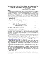
3.1 Montage ohne Flansch – A
Beim Einbau Stöße vermeiden,
keinen Hammer verwenden!
• Innengewinde g
1
mit Mindesttiefe L
herstellen.
• Anlagefläche (3) an der Maschine mit
Mindestdurchmesser D
1
herstellen.
• Verbindungsgewinde auf der Mutter
(4) mit Loctite 638 oder einem
vergleichbaren Klebstoff bestreichen
– dabei unbedingt die Hinweise des
Klebstoffherstellers beachten.
• Mutter eindrehen und mit Anzieh-
drehmoment M
A1
festziehen.
• Fluchtung der Spindelendenlagerung
beachten.
3.2 Montage mit Flansch – B
Beim Einbau Stöße vermeiden,
keinen Hammer verwenden!
• Innengewinde g
1
und Anlageflächen
an Flansch (5) und Maschine
(6)
herstellen.
• Verbindungsgewinde auf der Mutter
(7) mit Loctite 638 oder einem
vergleichbaren Klebstoff bestreichen
– dabei unbedingt die Hinweise des
Klebstoffherstellers beachten.
• Mutter eindrehen und mit Anzieh-
drehmoment M
A1
festziehen.
• Flansch an der Maschine anschrau-
ben.
Die Abmessungen der Schrauben (8)
und das Anziehdrehmoment M
A2
sind
lediglich Empfehlungen!
0,6 g 0,3 ml
0,6 g 0,3 ml
1,7 g 0,3 ml
1,7 g 0,3 ml
2,0 g 0,3 ml
2,4 g 0,6 ml
Größe Grundschmierung mit Fett Grundschmierung mit Öl
Size Basic lubrication with grease Basic lubrication with oil
Taille Lubrification de base à la graisse Lubrification de base à l’huile
Grandezza Lubrificazione di base con grasso Lubrificazione di base a olio
4. Grundschmierung
• Verträglichkeit zwischen Konservie-
rungsmittel und Schmierstoff
beachten. Siehe auch Leitfaden
Schmierung.
– Wenn keine Dichtungen eingebaut
sind:
• Entweder manuell mit Öl oder Fett
direkt die Spindel schmieren.
• Oder Schmieranschluss in der
Mutter (siehe 2.) benutzen.
Schmierstoff einführen, bis
Schmierstoff zwischen Mutter und
Spindel austritt.
– Wenn Dichtungen eingebaut sind:
• Schmieranschluss in der Mutter
(siehe 2.) benutzen. Schmierstoff-
menge siehe Tabelle.
5. Wartung
Das Nachschmierintervall ist
von vielen Faktoren wie z. B. Ver-
schmutzungsgrad, Betriebs-
temperatur, Belastung abhängig.
Deshalb können die Angaben in der
Tabelle nur Richtwerte sein.
• Bei Ölschmierung spätestens nach
zehn Stunden Einsatzdauer nach-
schmieren!
1 Umdrehungen
2 Laufweg der Mutter
3 Fettmenge
4 Ölmenge
12 x 5R x 2 - 3
12 x 10R x 2 - 2
16 x 5L x 3 - 3
16 x 5R x 3 - 3
16 x 10R x 3 - 3
20 x 5R x 3 - 4
Größe Nachschmierung mit Fett Nachschmierung mit Öl
Size In-service lubrication with grease In-service lubrication with oil
Taille Relubrification à la graisse Relubrification à l’huile
Grandezza Rilubrificazione con grasso Rilubrificazione a olio
Instructions ZEV-E-S
4
Bosch Rexroth AG
Linear Motion and Assembly Technologies
R310D4 3380 (2004.08)
3.1 Mounting without flange – A
Avoid impacts during installa-
tion. Do not use a hammer!
• Tap a female thread g
1
of minimum
depth L.
• Machine a mating surface (3) of min-
imum diameter D
1
on the machine.
• Apply Loctite 638 or a comparable
adhesive to the connection thread
on the nut (4). Follow the adhesive
manufacturer’s instructions carefully.
• Screw in the nut and tighten it with
tightening torque M
A1
.
• Make sure the screw end bearings
are properly aligned.
3.2 Mounting with flange – B
Avoid impacts during installa-
tion. Do not use a hammer!
• Tap the female thread g
1
and ma-
chine the mating surfaces on the
flange (5) and the machine (6).
• Apply Loctite 638 or a comparable
adhesive to the connection thread
on the nut (7). Follow the adhesive
manufacturer’s instructions carefully.
• Screw in the nut and tighten it with
tightening torque M
A1
.
• Fasten the flange to the machine.
The dimensions of the screws (8) and
the tightening torque M
A2
are recom-
mendations only!
4. Basic lubrication
• Make sure the lubricant is compatible
with the anti-corrosion oil. Refer also
to the Lubrication Guide.
– If no seals are installed:
• Either lubricate the screw directly
by hand using oil or grease,
• Or use the lube port in the nut
(see 2.). Inject lubricant until ex-
cess emerges between the nut
and the screw.
– If seals are installed:
• Use the lube port in the nut (see
2.). For lubricant quantity, see
table.
5. Maintenance
The in-service lubrication inter-
val will depend on many factors like
degree of soiling, operating tempera-
ture and load. The figures in the table
are given as a guide only.
• For oil lubrication, relubricate at the
latest after ten hours in service!
1 Revolutions
2 Nut travel
3 Grease quantity
4 Oil quantity
3.1 Montage sans bride – A
Eviter les chocs lors du mon-
tage. Ne pas utiliser de marteau !
• Tarauder l’alésage intérieur g
1
à la
profondeur minimum L.
• Réaliser la surface d’appui (3) sur la
machine au diamètre minimum D
1
.
• Enduire le filetage de liaison de
l’écrou (4) de Loctite 638 ou d’une
colle similaire – en respectant les
indications du fabricant.
• Visser l’écrou et le serrer au couple
de serrage M
A1
.
• Vérifier l’alignement du boîtier d’ex-
trémité de la vis.
3.2 Montage avec bride – B
Eviter les chocs lors du mon-
tage. Ne pas utiliser de marteau !
• Réaliser le taraudage g
1
et les sur-
faces d’appui sur la bride (5) et sur
la machine (6).
• Enduire le filetage de liaison de
l’écrou (7) de Loctite 638 ou d’une
colle similaire – en respectant les
indications du fabricant.
• Visser l’écrou et le serrer au couple
de serrage M
A1
.
• Visser la bride sur la machine.
Les dimensions des vis (8) et le cou-
ple de serrage M
A2
ne sont que des
recommandations !
4. Lubrification de base
• Vérifier la compatibilité de l’agent de
conservation avec le lubrifiant. Voir
également le Guide de lubrification.
– En l’absence des racleurs :
• lubrifier directement la vis à l’huile
ou à la graisse manuellement,
• ou utiliser le raccordement de
lubrification de l’écrou (voir 2.).
Introduire du lubrifiant jusqu’à ce
que celui-ci suinte entre l’écrou et
la vis.
– Lorsqu’il y a des racleurs :
• utiliser le raccordement de lubrifi-
cation de l’écrou (voir 2.). Quanti-
té de lubrifiant : voir le tableau.
5. Entretien
L’intervalle de relubrification
dépend de différents facteurs, com-
me le degré d’impuretés, la tempé-
rature de service et la charge. Les
indications du tableau ne sont donc
que des valeurs indicatives.
• Lubrification à l’huile : relubrifier après
dix heures de service maximum !
1 Nombre de tours
2 Course de l’écrou
3 Quantité de graisse
4 Quantité d’huile
3.1 Montaggio senza flangia – A
Durante il montaggio evitare
urti e non utilizzare martello!
• Preparare la filettatura interna g
1
con
profondità minima L.
• Preparare la superficie di contatto
(3) nella macchina con diametro
minimo D
1
.
• Applicare Loctite 638 o un collante
analogo sulla filettatura di collega-
mento della chiocciola (4) osservan-
do tassativamente le avvertenze del
produttore del collante.
• Avvitare la chiocciola e serrare
con coppia M
A1
.
• Badare all’allineamento del supporto
della vite.
3.2 Montaggio con flangia – B
Durante il montaggio evitare
urti e non utilizzare martello!
• Preparare la filettatura interna g
1
e le
superfici di contatto nella flangia (5)
e nella macchina (6).
• Applicare Loctite 638 o un collante
analogo sulla filettatura di collega-
mento della chiocciola (7) osservan-
do tassativamente le avvertenze del
produttore del collante.
• Avvitare la chiocciola e serrare con
coppia M
A1
.
• Avvitare la flangia alla macchina.
Le dimensioni delle viti (8) e la cop-
pia di serraggio M
A2
sono soltanto
raccomandazioni!
4. Lubrificazione di base
• Far attenzione a che mezzo anticorro-
sione e lubrificante siano compatibili.
Vedere anche la guida Lubrificazione.
– Se non sono montate guarnizioni:
• lubrificare la vite applicando diret-
tamente a mano olio o grasso,
• oppure utilizzare il raccordo di
lubrificazione che si trova nella
chiocciola (vedere 2.). Introdurre
lubrificante fino a che esso fuo-
riuscirà fra la chiocciola e la vite.
– Se sono montate guarnizioni:
• utilizzare il raccordo di lubrificazio-
ne che si trova nella chiocciola
(vedere 2.). Per quantità di lubri-
ficante vedere la tabella.
5. Manutenzione
L’intervallo di rilubrificazione
dipende da molti fattori come p. es.
grado di sporco, temperatura d’eser-
cizio e carico. Pertanto, le indicazioni
riportate nella tabella sono solo valori
orientativi.
• In caso di lubrificazione ad olio, rilu-
brificare al massimo dopo dieci ore
di durata d’impiego!
1 Giri
2 Percorrenza
3 Quantità di grasso
4 Quantità di olio