Tài liệu ASM Metals HandBook P14 pdf
Bạn đang xem bản rút gọn của tài liệu. Xem và tải ngay bản đầy đủ của tài liệu tại đây (227.58 KB, 10 trang )
Fig. 9 Redesign of a MIM part to establish uniform wall thickness. Source: Ref 8
Material Selection. The material systems currently in commercial use include ferrous alloys (low-alloy steel, stainless
steels, soft magnetic alloys), nonferrous alloys (brass, bronze), tungsten carbide, pure nickel, electronic alloys (Invar,
Kovar), and tungsten-copper composites. The physical and mechanical properties of several MIM engineering alloys
(low-alloy steel and stainless steels) have been standardized by MPIF (Ref 10). After sintering, the residual porosity in
MIM parts is very low and not interconnected. With densities typically in excess of 96% of theoretical density, the
resultant mechanical properties are superior to conventional die-compacted P/M materials and more closely match the
properties of investment castings in similar alloys. Therefore, the limitations discussed previously regarding the residual
porosity in conventional die-compacted products do not apply to MIM parts. Secondary operations can be performed with
no restrictions.
References cited in this section
8. Powder Metallurgy Design Manual, 2nd ed., Metal Powder Industries Federation, 1995
10. "Material Standards for Metal Injection Molded Parts," Standard 35 1993-1994 edition, Metal Powder
Industries Federation, 1993
Powder Metallurgy Methods and Design
*
Howard I. Sanderow, Management & Engineering Technologies
Powder Forging
The design issues in P/F are similar to the requirement of any precision, closed-die forging. The difference is the starting
preform; in the case of P/F, the preform is a sintered powder metal part, typically 80 to 85% of theoretical density, with a
shape similar to the final part configuration. By contrast, in a precision closed-die forging the preform is a wrought steel
blank with very little shape detail. Preform design for P/F fabrication determines the extent of product shape detail
required to meet the performance requirements of the finished P/F part. Preform design is a complex, iterative process
currently modeled by computer simulation software programs to help reduce design time and development costs.
In the forging step, the P/M preform is removed from the reheat (or sintering) furnace, coated with a die lube, and forged
in a heated, closed die operation. The forging process reduces the preform height and forces metal into the recesses of the
closed die. This step also brings all features to their final tolerances and densities.
Configuration guidelines, typical of precision closed-die forged parts, also apply to P/F parts as follows:
• Radii on inside corners of the forging as large as possible to promote metal flow around corners in the
tool and promote complete fill of all details.
• Radii of at least 1 mm (0.040 in.) on all outside corners of the forging to aid in material flow to define
features.
• Shape of the forging should be such that, when placed in the die, the lateral forces will be balanced.
Shapes that are symmetrical along a vertical plane, such as connecting rods and shapes that are
axisymmetric (or nearly so), are preferred.
• Zero draft is possible on surfaces formed by the die and core rod, but not by the upper punch.
• Re-entrant angles (undercuts) cannot be forged.
• Axial tolerances--in the direction of forging--are driven by variations in the mass of metal in the
preform. Lateral tolerances are driven by metal flow as the cavity fills. Typical axial tolerance of 0.25 to
0.5 mm (0.010 to 0.020 in.) are encountered, with diametric tolerances of 0.003 to 0.005 mm/mm of
diameter.
• Concentricity of a P/F part is determined by the quality and density distribution in the preform.
Concentricity is normally double that of the preform.
Powder Metallurgy Methods and Design
*
Howard I. Sanderow, Management & Engineering Technologies
References
1. F.V. Lenel, Powder Metallurgy--Principles and Applications, Metal Powder Industries Federation, 1980, p
426
2. L.F. Pease III and V.C. Potter, Mechanical Properties of P/M Materials, Powder Metallurgy, Vol 7, ASM
Handbook (formerly Metals Handbook, 9th ed.), American Society for Metals, 1984, p 467
3. H.I. Sanderow, H. Rodrigues, and J.D. Ruhkamp, New High Strength 4100 Alloy P/M Steels, Prog.
Powder Metall., Vol 41, Metal Powder Industries Federation, 1985, p 283
4. D. Gay and H. Sanderow, The Effect of Sintering Conditions on the Magnetic and Mechanical Properties
of Warm Compacted Fe-P P/M Steels, Advances in Powder Metallurgy and Particulate Materials--1996,
Vol 6, Metal Powder Industries Federation, 1996, p 20-127
5. "Material Standards for P/M Structural Parts," Standard 35 1994 edition, Metal Powder Industries
Federation, 1994
6. "Standard Specification for Powder Forged (P/F) Ferrous Structural Parts," B 848-94, Annual Book of
ASTM Standards, American Society for Testing and Materials
7. R.M. German, Powder Metallurgy Science, 2nd ed., Metal Powder Industries Federation, 1994, p 193
8. Powder Metallurgy Design Manual, 2nd ed., Metal Powder Industries Federation, 1995
9. "Material Standards for P/M Self-Lubricating Bearings," Standard 35 1991-1992 edition, Metal Powder
Industries Federation, 1991
10. "Material Standards for Metal Injection Molded Parts," Standard 35 1993-1994 edition, Metal Powder
Industries Federation, 1993
Advances in Powder Metallurgy Applications
F.H. "Sam" Froes, Institute for Materials and Advanced Processes (IMAP), University of Idaho, and John Hebeisen, Bodycote IMT,
Inc.
Introduction
POWDER METALLURGY parts can be broadly separated into three categories: those in which the P/M approach allows
a lower-cost component to be produced, an intermediate category of cost-effective/high-performance parts, and those in
which the P/M approach leads to a part with enhanced mechanical property characteristics (Ref 1, 2, 3). The first
approach generally results in a product with lower mechanical properties than wrought product, the third is normally a
higher-cost approach. The low-cost P/M product is the more traditional commercial approach, the second has been more
recently established commercially, and high-performance parts represent a developing facet of P/M technology.
Many P/M parts are now used in a variety of industries, including automobiles, household appliances, yard and garden
equipment, computers, fabric industry equipment, and orthodontic devices (Ref 4). The growth in North American metal
powder shipments up to 1996 is shown in Table 1 (Ref 5).
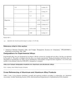
Table 1 North American metal powder shipments
Shipments, tons
1992 1993 1994 1995 1996
Iron and steel
246,300 287,550 337,850 347,172 350,603
Copper and copper base
20,000 22,400 23,100 23,216 22,891
Aluminum
29,700 29,500 43,700 37,044 34,179
Molybdenum
2,500(E) 2,500(E) 2,500(E) 2,500(E) 2,500(E)
Tungsten
1,450 1,900 1,450 1,445 1,000(E)
Tungsten carbide
4,500 5,200 6,200 10,846 11,200(E)
Nickel
9,900 9,600 10,000 10,476 11,600(E)
Tin
950 1,100 1,250 1,010 1,010
Total
315,300 359,750 426,050 433,709 434,983
Source: Ref 5
(a)
E, estimate.
In 1995, North American powder metal shipments totaled 437,774 tons, a 2% increase from the previous year. Iron and
steel powder shipments amounted to 347,172 tons, up 2.7% from 1994. Parts applications for iron/steel powders
accounted for a record-high 312,974 tons, an increase of 3.1%. However, it was the first time in four years that the parts
market improved by a percentage of less than double digits. In the 1992 to 1994 period, the parts market for North
American iron and steel powder producers, the biggest market of its kind in the world, grew at an average annual rate of
18.6%.
Automotive parts continue to be the leading application of P/M parts. The typical U.S. automobile contains about 14 kg
(30 lb) of P/M parts with an increase expected in the next several years (Fig. 1). A slightly lower amount is used in
Japanese automobiles (Table 2) (Ref 6), but automotive application of P/M parts is still the dominant use in Japan as well
(Fig. 2). The growth of P/M parts in automobiles is due to increased use of P/M components in engines, transmissions,
brakes, airbags, and other complex parts. Emerging automotive applications are also described at the end of this article.
Table 2 Average weight of P/M components used in each Japanese car
Weight Year Cars,
×10
3
P/M part, t
kg/car lb/car
1980
11,175 33,923 3.03 6.68
1987
12,350 52,921 4.29 9.46
1988
12,819 60,046 4.68 10.3
1989
12,953 70,138 5.41 11.9
1990
13,592 75,459 5.55 12.2
1991
13,145 75,099 5.71 12.6
Fig. 1 Growth of powder metallurgy in Ford automobiles

