Tài liệu Student Learning Guide Course Introduction P2 pdf
Bạn đang xem bản rút gọn của tài liệu. Xem và tải ngay bản đầy đủ của tài liệu tại đây (598.25 KB, 10 trang )
A
UTOMOTIVE
E
LECTRICAL
C
IRCUIT
A
NALYSIS
m o d u l e E C 1
1
After completing this module, you will be able
to identify how different types of automotive
electrical circuits are designed to operate
and the methods used in controlling electrical
behavior in a circuit.
To enable you to diagnose and repair Kia
automotive electrical problems faster and more
effectively.
Carefully read this material. Study each
illustration as you read the material. Feel free
to ask questions any time something is not
clear. Be sure to answer the questions at the
end of the module.
• Module
• Electrical project board and accessories
• DVOM
• Identify circuit elements: power source,
load, protection device and ground
• Identify the different types of circuits
and circuit control methods
• Determine what is required to make the
circuit operate
• Apply the relationship between volts,
amps and ohms to diagnose a faulty
electrical circuit
EC1-1
LEARNING OBJECTIVES
MODULE DIRECTIONS
THINGS YOU WILL NEED
A
UTOMOTIVE
E
LECTRICAL
C
IRCUIT
A
NALYSIS
m o d u l e E C 1
2
ELECTRICAL CIRCUITS
The path that electricity flows through is called
a circuit. The circuit must form a complete
loop from the positive side of the power source
to the negative side of the power source.
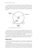
Electrical behavior in a circuit is determined by
the design of the circuit, the number and types
of load devices, the size of the conductors and
the types of control devices used by the circuit.
Electrical Circuit Components
A basic automotive electrical circuit consists
of a voltage source (battery, generator),
conductors (usually wires or the vehicle body)
and one or more load devices that perform
some type of useful work such as lamps,
motors, etc.
Most electrical circuits have at least one
protection device such as a fuse, a circuit
breaker or a fusible link and one or more
control devices including switches, relays and
solid-state devices such as transistors.
Component Descriptions
VoltageVoltage (Power) Source - The device that
provides the potential or pressure to move
electrons through the circuit.
Conductors - Provide a “controlled path” for
current flow from and back to the power source.
Load Devices - Convert electrical energy into
another form such as heat, light or mechanical
energy so the circuit can perform useful work.
Protection Devices - Provide an intentional
open circuit when current exceeds specified
limits.
Control Devices - can control the amount and
direction of current flow through a circuit.
• Voltage source provides
pressure to move electrons
• Conductors provide a
“controlled path” for current
flow
• Load devices convert
electrical energy into
another form so the circuit
can perform useful work
• Intentional opening of
protection devices protect
the circuit
EC1-4
EC1-3
• A circuit is a path for current
to flow
• Electrical behavior in a
circuit is influenced by:
- Design of the circuit
- Number and types of load
devices
- Size of the conductors
- Types of control devices
EC1-2
SWITCH
(CONTROL
DEVICE)
A
UTOMOTIVE
E
LECTRICAL
C
IRCUIT
A
NALYSIS
m o d u l e E C 1
3
Types of Control Devices
The most common types of control devices used
in automotive electrical circuits are shown in the
illustration.
Switch - A device that mechanically opens and
closes an electrical circuit. Some switches are
controlled by pressure, temperature or light.
Relay - An electromechanical device that
utilizes a small amount of current to energize
an electromagnet that closes the contacts in a
circuit carrying a higher amount of current. The
electromagnet in a relay has a fixed core that
attracts a moveable armature.
Transistor - Semiconductor devices that function
as switches with no moving parts. As the name
implies, semiconductors conduct electricity part
of the time and do not conduct at other times.
These qualities let transistors function like electric
relays.
Electronic Control Unit (ECU) - Often referred
to as “the computer”, these units are nothing
more than sophisticated switches. Like any other
switching device, an ECU can be the control
device in ground or power controlled circuits.
Other Types of Devices
Solenoid - An electromechanical device that
utilizes a small amount of current to energize
an electromagnet that closes the contacts in a
circuit carrying a higher amount of current. The
electromagnet in a solenoid has a moveable core
that is pulled into the hollow coil.
Diode - Semiconductor devices that work like an
electrical one way valve by allowing current to
flow in only one direction. Commonly used when
changing alternating current into direct current.
Capacitor - An electrical component that can
store a small charge and then release it as
needed. They can be used to store and release
a high voltage, protect a circuit against surges or
smooth out current fluctuations
• Switch
Mechanical device that
opens or closes the circuit
• Relay
An electromagnet with a
fixed core that attracts a
moveable armature
• Transistor
Works like a relay but has
no moving parts
• Electronic Control Unit
Sophisticated switch
Receives signals from
sensors then controls
actuators
EC1-6
• Solenoid
An electromagnet with a
moveable core that is pulled
into the coil
• Diode
A semiconductor device that
allows current to flow in only
one direction
• Capacitor
Can store a small charge which
can be released when needed
to make a current flow for a
short period
EC1-7
• Turn electrical circuit on or off
• Used on either power side or
ground side of circuit
EC1-5
A
UTOMOTIVE
E
LECTRICAL
C
IRCUIT
A
NALYSIS
m o d u l e E C 1
4
• Relationship between voltage,
amperage and resistance in an
electrical circuit
• Current is directly proportional
to voltage and inversely
proportional to the resistance
in a circuit
• Published by George Simon
Ohm in 1826
• One volt of pressure will cause
one ampere of current to flow
in a circuit with a resistance of
one ohm EC1-8
E = Voltage measured in
Volts
I = Current measured in
Amps
R =
Resistance measured
in Ohms
S O L V I N G C I R C L E
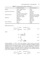
The relationship between voltage, current and
resistance is such that any one value can be
found when there are two known values. To
make this easier to understand we can put
Ohm’s law in the form of the formula
E = I X R.
In this formula, E represents voltage, I
represents current and R represents resistance.
To find current, we use the formula
I = E/R
and to find resistance we use the formula
R = E/I.
Using the divided circle method makes it easier
to remember the formulas.
OHM’S LAW
In 1826 a German scientist named George
Simon Ohm published his findings of the
relationship between voltage, amperage and
resistance in an electrical circuit. These
findings were proved to be true and were
named “Ohm’s Law.” Ohm’s Law states that
the current that flows in a circuit is directly
proportional to the voltage and inversely
proportional to the resistance in the circuit.
One volt of pressure will cause one ampere of
current to flow in a circuit with a resistance of
one ohm.
Ohm’s Law Relationship
If the resistance stays constant...current goes
up as voltage goes up and current goes down
as voltage goes down.
If voltage stays constant...current goes up as
resistance goes down and current goes down
as resistance goes up.
EC1-13
A
UTOMOTIVE
E
LECTRICAL
C
IRCUIT
A
NALYSIS
m o d u l e E C 1
5
E
R
12v
4
12
4
Ohms
RI
=
4
=
3
A
=
3
I= Amps E = Volts R = Ohms
E
I
=
3
12v
12
3
=
4
Ohms
3
X
4
=
12
V
P = Power measured in
Watts
I = Current measured in
Amps
E =
Voltage measured in
Volts
S O L V I N G C I R C L E
S O L V I N G T A B L E
The same relationship may be found between
power, current and voltage. To find the power
or wattage used in a circuit we can use the
formula P = I X E. We can also find current by
using the formula I = P/E or find voltage using
the formula E = P/I. To remember the formulas
use the divided circle method.
EC1-14