Tài liệu Laser điốt được phân phối thông tin phản hồi và các bộ lọc du dương quang P2 doc
Bạn đang xem bản rút gọn của tài liệu. Xem và tải ngay bản đầy đủ của tài liệu tại đây (504.15 KB, 48 trang )
2
Principles of Distributed Feedback
Semiconductor Laser Diodes:
Coupled Wave Theory
2.1 INTRODUCTION
The rapid development of both terrestrial and undersea optical fibre networks has paved the
way for a global communication network. Highly efficient semiconductor injection lasers
have played a leading role in facing the challenges of the information era. In this chapter,
before discussing the operating principle of the semiconductor distributed feedback (DFB)
laser diode (LD), general concepts with regard to the principles of lasers will first be
presented. In section 2.2.1, general absorption and emission of radiation will be discussed
with the help of a simple two-level system. In order for any travelling wave to be amplified
along a two-level system, the condition of population inversion has to be satisfied and the
detail of this will be presented in section 2.2.2. Due to the dispersive nature of the material,
any amplification will be accompanied by a finite change of phase. In section 2.2.3, such
dispersive properties of atomic transitions will be discussed.
In semiconductor lasers, rather than two discrete energy levels, electrons jump between
two energy bands which consist of a finite number of energy levels closely packed together.
Following the Fermi–Dirac distribution function, population inversion in semiconductor
lasers will be explained in section 2.3.1. Even though the population inversion condition is
satisfied, it is still necessary to form an optical resonator within the laser structure. In section
2.3.2, the simplest Fabry–Perot (FP) etalon, which consists of two partially reflecting mirrors
facing one another, will be investigated. A brief historical development of semiconductor
lasers will be reviewed in section 2.3.3. The improvements in both the lateral and transverse
carrier confinements will be highlighted. In semiconductor lasers, energy comes in the form
of external current injection and it is important to understand how the injection current can
affect the gain spectrum. In section 2.3.4, various aspects that will affect the material gain
of the semiconductor will be discussed. In particular, the dependence of the carrier
concentration on both the material gain and refractive index will be emphasised. Based on
the Einstein relation for absorption, spontaneous emission and stimulated emission rates, the
carrier recombination rate in semiconductors will be presented in section 2.3.5.
Distributed Feedback Laser Diodes and Optical Tunable Filters H. Ghafouri–Shiraz
# 2003 John Wiley & Sons, Ltd ISBN: 0-470-85618-1
The FP etalon, characterised by its wide gain spectrum and multi-mode oscillation, has
limited use in the application of coherent optical communication. On the other hand, a single
longitudinal mode (SLM) oscillation becomes feasible by introducing a periodic corrugation
along the path of propagation. The periodic corrugation which backscatters all waves
propagating along one direction is in fact the working principle of the DFB semiconductor
laser. The periodic Bragg waveguide acts as an optical bandpass filter so that only frequency
components close to the Bragg frequency will be coherently reinforced. Other frequency
terms are effectively cut off as a result of destructive interference. In section 2.4, this
physical phenomenon will be explained in terms of a pair of coupled wave equations. Based
on the nature of the coupling coefficient, DFB semiconductor lasers are classified into purely
index-coupled, mixed-coupled and purely gain- or loss-coupled structures. The periodic
corrugations fabricated along the laser cavity play a crucial role since they strongly affect
the coupling coefficient and the strength of optical feedback. In section 2.5, the impact due
to the shape of various corrugations will be discussed. Results based on a five-layer separate
confinement structure and a general trapezoidal corrugation function will be presented. A
summary is to be found at the end of this chapter.
2.2 BASIC PRINCIPLE OF LASERS
2.2.1 Absorption and Emission of Radiation
From the quantum theory, electrons can only exist in discrete energy states when the
absorption or emission of light is caused by the transition of electrons from one energy state
to another. The frequency of the absorbed or emitted radiation f is related to the energy
difference between the higher energy state E
2
and the lower energy state E
1
by Planck’s
equation such that
E ¼ E
2
E
1
¼ h f ð2:1Þ
where h ¼ 6:626 10
34
Js is Planck’s constant. In an atom, the energy state corresponds to
the energy level of an electron with respect to the nucleus, which is usually marked as the
ground state. Generally, energy states may represent the energy of excited atoms, molecules
(in gas lasers) or carriers like electrons or holes in semiconductors.
In order to explain the transitions between energy states, modern quantum mechanics
should be used. It gives a probabilistic description of which atoms, molecules or carriers are
most likely to be found at specific energy levels. Nevertheless, the concept of stable energy
states and electron transitions between two energy states are sufficient in most situations.
The term photons has always been used to describe the discrete packets of energy released
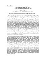
or absorbed by a system when there is an interaction between light and matter. Suppose a
photon of energy (E
2
E
1
) is incident upon an atomic system as shown in Fig. 2.1 with two
energy levels along the longitudinal z direction. An electron found at the lower energy state
E
1
may be excited to a higher energy state E
2
through the absorption of the incident photon.
This process is called an induced absorption. If the two-level system is considered a closed
system, the induced absorption process results in a net energy loss. Alternatively, an electron
found initially at the higher energy level E
2
may be induced by the incident photon to jump
back to the lower energy state. Such a change of energy will cause the release of a single
photon at a frequency f according to Planck’s equation. This process is called stimulated
32
PRINCIPLES OF DISTRIBUTED FEEDBACK SEMICONDUCTOR LASER DIODES
emission. The emitted photon created by stimulated emission has the same frequency as the
incident initiator. In addition, output light associated with the incident and stimulated
photons shares the same phase and polarisation state. In this way, coherent radiation is
achieved. Contrary to the absorption process, there is an energy gain for stimulated
emissions.
Apart from induced absorption and stimulated emissions, there is another type of
transition within the two-level system. An electron may jump from the higher energy state
E
2
to the lower energy state E
1
without the presence of any incident photon. This type of
transition is called a spontaneous emission. Just like stimulated emissions, there will be a net
energy gain at the system output. However, spontaneous emission is a random process and
the output photons show variations in phase and polarisation state. This non-coherent
radiation created by spontaneous emission is important to the noise characteristics in
semiconductor lasers.
2.2.2 The Einstein Relations and the Concept of Population Inversion
In order to create a coherent optical light source, it is necessary to increase the rate of
stimulated emission while minimising the rate of absorption and spontaneous emission. By
examining the change of field intensity along the longitudinal direction, a necessary
condition will be established.
Let N
1
and N
2
be the electron populations found in the lower and higher energy states of
the two-level system, respectively. For uniform incident radiation with energy spectral
density
f
, the total induced upward transition rate R
12
(subscript 12 indicates the transition
from the lower energy level 1 to the higher energy level 2) can be written as
R
12
¼ N
1
B
12
f
¼ W
12
N
1
ð2:2Þ
where B
12
is the constant of proportionality known as the Einstein coefficient of absorption.
The product B
12
f
is commonly known as the induced upward transition rate W
12
.
Figure 2.1 Different recombination mechanisms found in a two-energy level system.
BASIC PRINCIPLE OF LASERS
33
An excited electron on the higher energy state can undergo downward transition through
either spontaneous or stimulated emission. Since the rate of spontaneous emissions is
directly proportional to the population N
2
, the overall downward transition rate R
21
becomes
R
21
¼ A
21
N
2
þ N
2
B
21
f
¼ A
21
N
2
þ W
21
N
2
ð2:3Þ
where the stimulated emission rate is expressed in a similar manner as the rate of absorption.
A
21
is the spontaneous transition rate and B
21
is the Einstein coefficient of stimulated
emission. Subscript 21 indicates a downward transition from the higher energy state 2 to the
lower energy state 1. Correspondingly, W
21
¼ B
21
f
is known as the induced downward
transition rate.
For a system at thermal equilibrium, the total upward transition rate must equal the total
downward transition rate and therefore R
12
¼ R
21
, or in other words
N
1
B
12
f
¼ A
21
N
2
þ N
2
B
21
f
ð2:4Þ
By rearranging the previous equation, it follows that
f
¼
A
21
=B
21
B
12
N
1
B
21
N
2
1
!
ð2:5Þ
At thermal equilibrium, the population distribution in the two-level system is described by
Boltzmann statistics such that
N
2
N
1
¼ e
E=kT
ð2:6Þ
where k ¼ 1:381 10
23
JK
1
is the Boltzmann constant. Substituting eqn (2.6) into (2.5)
gives
f
¼
A
21
=B
21
B
12
B
21
e
E=kT
1
!
ð2:7Þ
Since the two-level system is in thermal equilibrium, it is usual to compare the above
equations with a blackbody radiation field at temperature T which is given as [1]
f
¼
8pn
3
hf
3
c
3
1
e
E=kT
1
ð2:8Þ
where n is the refractive index and c is the free space velocity. By equating eqn (2.7) with
(2.8), one can derive the following relations
B
12
¼ B
21
¼¼> W
12
¼ W
21
¼ W ð2:9Þ
34
PRINCIPLES OF DISTRIBUTED FEEDBACK SEMICONDUCTOR LASER DIODES
and
A
21
B
21
¼
8pn
3
hf
3
c
3
ð2:10Þ
From eqn (2.7), it is clear that the upward and downward induced transition rates are
identical at thermal equilibrium. Therefore, using eqn (2.9), the final induced transition rate,
W, becomes
W ¼
A
21
c
3
8pn
3
hf
3
f
¼
A
21
c
2
8pn
2
hf
3
I ð2:11Þ
where I ¼ c
f
=n is the intensity (Wm
2
) of the optical wave.
Since energy gain is associated with the downward transitions of electrons from a higher
energy state to a lower energy state, the net induced downward transition rate of the two-
level system becomes ðN
2
N
1
ÞW. Therefore, the net power generated per unit volume V
can be written as
dP
0
dV
¼ðN
2
N
1
ÞW hf ð2:12Þ
In the absence of any dissipation mechanism, the power change per unit volume is
equivalent to the intensity change per unit longitudinal length. Substituting eqn (2.12) into
(2.11) will generate
dI
dz
¼
dP
0
dV
¼ðN
2
N
1
Þ
A
21
c
2
8pn
2
f
2
IðzÞð2:13Þ
The general solution of the above first-order differential equation is given as
IðzÞ¼I
0
e
I
ð fÞz
ð2:14Þ
where
I
ð fÞ¼ðN
2
N
1
Þ
A
21
c
2
8pn
2
f
2
ð2:15Þ
In the above equation,
I
ð fÞ is the frequency-dependent intensity gain coefficient. Hence, if
I
ðfÞ is greater than zero, the incident wave will grow exponentially and there will be an
amplification. However, recalling the Boltzmann statistics from eqn (2.6), the electron
population N
2
in the higher energy state is always less than that of N
1
found in the lower
energy state at positive physical temperature. As a result, energy is absorbed at thermal
equilibrium for the two-level system. In addition, according to eqns (2.8) and (2.10), the rate
of spontaneous emission ðA
21
Þ is always dominant over the rate of stimulated emission
ðB
21
f
Þ at thermal equilibrium.
BASIC PRINCIPLE OF LASERS
35
Mathematically, there are two possible ways one can create a stable stream of coherent
photons. One method involves negative temperature which is physically impossible. The
other method is to create a non-equilibrium distribution of electrons so that N
2
> N
1
.This
condition is known as population inversion. In order to fulfil the requirement of population
inversion, it is necessary to excite some electrons to the higher energy state in a process
commonly known as ‘pumping’. An external energy source is required, which in a
semiconductor injection laser, takes the form of an electric current.
2.2.3 Dispersive Properties of Atomic Transitions
Physically, an atom in a dielectric acts as a small oscillating dipole when it is under the
influence of an incident oscillating electric field. When the frequency of the incident wave is
close to that of the atomic transition, the dipole will oscillate at the same frequency as the
incident field. Therefore, the total transmitted field will be the sum of the incident field and
the radiated fields from the dipole. However, due to spontaneous emissions, the radiated field
may not be in phase with the incident field. As we shall discuss, such a phase difference will
alter the propagation constant as well as the amplitude of the incident field. Hence, apart
from induced transitions and photonic emissions, dispersive effects should also be
considered.
Classically, for the simple two-level system with two discrete energy levels, the dipole
moment problem can be represented by an electron oscillator model [2]. This model is a
well-established method used long before the advent of quantum mechanics. Based upon the
electron oscillator model, an oscillating dipole in a dielectric is replaced by an electron
oscillating in a harmonic potential well. The effect of dispersion is measured by the change
of relative permittivity with respect to frequency. In the electron oscillator model, any
electric radiation at angular frequency near to the resonant angular frequency !
0
is
characterised by a frequency-dependent complex electronic susceptibility ð!Þ which
relates to the polarisation vector Pð!Þ such that
~
Pð!Þ¼"
0
ð!Þ
~
E ð2:16Þ
where
ð!Þ¼
0
ð!Þj
00
ð!Þð2:17Þ
0
and
00
being the real and imaginary components of the electronic susceptibility .
To start with, a plane electric wave propagating in a medium with complex permittivity of
"
0
ð!Þ will be considered. The wave, which is travelling along the longitudinal z direction,
can be expressed in phasor form such that
EðzÞ¼E
0
e
j!t
e
jk
0
ð!Þz
ð2:18Þ
where E
0
is a complex amplitude coefficient and k
0
ð!Þ, the propagation constant, can be
expressed as
k
0
ð!Þ¼!
ffiffiffiffiffiffiffi
"
0
p
ð2:19Þ
36
PRINCIPLES OF DISTRIBUTED FEEDBACK SEMICONDUCTOR LASER DIODES
From Maxwell’s equations, the complex permittivity of an isotropic medium, "
0
, is given as
"
0
ð!Þ¼" 1 þ
"
0
"
ð!Þ
ð2:20Þ
where " is the relative permittivity of the medium when there is no incident field. is the
same complex electronic susceptibility as mentioned previously. Using eqn (2.20) and
assuming ð"
0
="Þ jj1, one can obtain
k
0
ð!Þk 1 þ
"
0
2"
ð!Þ
ð2:21Þ
where
k ¼ !
ffiffiffiffiffiffi
"
p
ð2:22Þ
By expanding ð!Þ with eqn (2.21), the propagation constant k
0
becomes
k
0
ð!Þk1þ
0
ð!Þ
2n
2
j
k
00
ð!Þ
2n
2
ð2:23Þ
where n ¼ð"="
0
Þ
1=2
is the refractive index of the medium at a frequency far away from the
resonant angular frequency !
0
. Substituting eqn (2.21) back into eqn (2.18), the electric
plane wave becomes
EðzÞ¼E
0
e
j!t
e
jðkþÁkÞz
e
g
int
ðÞz=2
ð2:24Þ
where
int
is introduced to include any internal cavity loss and
Ákð!Þ¼k
0
ð!Þ
2n
2
ð2:25Þ
gð!Þ¼k
00
ð!Þ
n
2
ð2:26Þ
In semiconductor lasers, it is likely that free carrier absorption and scattering at the
heterostructure interface may contribute to internal losses. In the above equation, Ák
corresponds to a shift of propagation constant which is frequency dependent. Unless the
electric field oscillates at the resonant angular frequency !
0
, there will be a finite phase delay
and the new phase velocity of the incident wave becomes !=ðk þ ÁkÞ.
Apart from the phase velocity change, the last exponential term in eqn (2.24) indicates
an amplitude variation with g as the power gain coefficient. When ðg
int
Þ is greater than
zero, the electric plane wave will be amplified. Rather than the population inversion
condition relating the population density at the two energy levels as in eqn (2.14), the
imaginary part of the electronic susceptibility
00
ð!Þ is used to establish the amplifying
condition. Sometimes, the net amplitude gain coefficient
net
is used to represent the
necessary amplifying condition such that
net
¼
g
int
2
> 0 ð2:27Þ
BASIC PRINCIPLE OF LASERS
37
2.3 BASIC PRINCIPLES OF SEMICONDUCTOR LASERS
Before the operation of the semiconductor laser is introduced, some basic concepts of energy
transition between energy states will be discussed. When there is an interaction between
light and matter, discrete packets of energy (photons) may be released or absorbed by the
system. Suppose a photon of energy ðE
2
E
1
Þ is incident upon an atomic system with two
energy levels E
1
and E
2
along the longitudinal z direction. An electron at the lower energy
state E
1
may be excited to a higher energy state E
2
through the absorption of the incident
photon. This process is called induced absorption. If the two-level system is considered a
closed system, the induced absorption process results in a net energy loss. Alternatively, an
electron found initially at the higher energy level E
2
may be induced by the incident photon
to jump back to the lower energy state. Such a change of energy will cause the release of a
single photon at a frequency f according to Planck’s equation. This process is called
stimulated emission. The emitted photon created by stimulated emission has the same
frequency as the incident initiator. Furthermore, the incident and stimulated photons share
the same phase and polarisation state. In this way, coherent radiation is achieved. Contrary to
the absorption process, there is an energy gain for stimulated emissions.
Apart from induced absorption and stimulated emissions, an electron may jump from the
higher energy state to the lower energy state without the presence of any incident photon.
This type of transition is called a spontaneous emission and a net energy gain results at the
system output. However, spontaneous emission is a random process and the output photons
show variations in phase and polarisation state. This non-coherent radiation created
by spontaneous emission is important to the noise characteristics in semiconductor lasers.
2.3.1 Population Inversion in Semiconductor Junctions
In gaseous lasers like CO
2
or He–Ne lasers, energy transitions occur between two discrete
energy levels. In semiconductor lasers, these energy levels cluster together to form energy
bands. Energy transitions between these bands are separated from one another by an energy
barrier known as an ‘energy gap’ (or forbidden gap). With electrons topping up the ground
states, the uppermost filled band is called the valence band and the next highest energy band
is denoted the conduction band. The probability of an electronic state at energy E being
occupied by an electron is governed by the Fermi–Dirac distribution function, fðEÞ, such
that [3]
fðEÞ¼
1
e
ðEE
f
Þ=kT
þ 1
½
ð2:28Þ
where k is the Boltzmann constant, T is the temperature in Kelvin and E
f
is the Fermi level.
The concept of the Fermi level is important in characterising the behaviour of
semiconductors. By putting E ¼ E
f
in the above equation, the Fermi–Dirac distribution
function fðE
f
Þ becomes 1=2. In other words, an energy state at the Fermi level has half the
chance of being occupied. The basic properties of an equilibrium p–n junction will not be
covered here as they can be found in almost any solid state electronics textbook [4]. Only
some important characteristics of the p–n junction will be discussed here.
38
PRINCIPLES OF DISTRIBUTED FEEDBACK SEMICONDUCTOR LASER DIODES
According to Einstein’s relationship on the two-level system, the population of electrons
in the higher energy state needs to far exceed that of electrons found in the lower energy
state before any passing wave can be amplified. Such a condition is known as population
inversion. At thermal equilibrium, however, this condition cannot be satisfied. To form a
population inversion along a semiconductor p–n junction, both the p and n type materials
must be heavily doped (degenerate doping) so that the doping concentrations exceed the
density of states of the band. The doping is so heavy that the Fermi level is forced into the
energy band. As a result, the upper part of the valence band of the p type material (from
the Fermi level E
f
to the valence band edge E
v
) remains empty. Similarly, the lower part of
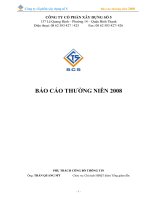
the conduction band is also filled by electrons due to heavy doping. Figure 2.2(a) shows the
energy band diagram of such a heavily doped p–n junction. At thermal equilibrium, any
energy transition between conduction and valence bands is rare.
Using an external energy source, the equilibrium can be disturbed. External energy comes
in the form of external biasing which enables more electrons to be pumped to the higher
energy state and the condition of population inversion is said to be achieved. When a
forward bias voltage close to the bandgap energy is applied across the junction, the depletion
layer formed across the p–n junction collapses. As shown in Fig. 2.2(b), the quasi-Fermi
level in the conduction band, E
Fc
, and that in the valence band E
Fv
are separated from one
another under a forward biasing condition. Quantitatively, E
Fc
and E
Fv
could be described in
terms of the carrier concentrations such that
N ¼ n
i
e
ðE
Fc
E
i
Þ=kT
ð2:29Þ
and
P ¼ n
i
e
ðE
i
E
Fv
Þ=kT
ð2:30Þ
where E
i
is the intrinsic Fermi level, n
i
is the intrinsic carrier concentration, N and P are the
concentration of electrons and holes, respectively. Along the p–n junction, there exists a
narrow active region that contains simultaneously the degenerate populations of electrons
and holes. Here, the condition of population inversion is satisfied and carrier recombination
starts to occur.
Figure 2.2 Schematic illustration of a degenerate homojunction. (a) Typical energy level diagram at
equilibrium with no biasing voltage; (b) the same homojunction under strong forward bias voltage.
BASIC PRINCIPLES OF SEMICONDUCTOR LASERS
39
Since the population distribution in a semiconductor follows the Fermi–Dirac distribution
function, the probability of an occupied conduction band at energy E
a
can be described by
f
c
ðE
a
Þ¼
1
1 þ e
ðE
a
E
Fc
Þ=kT
where E
a
> E
Fc
ð2:31Þ
Similarly, the probability of an occupied valence band at energy E
b
can be written as
f
v
ðE
b
Þ¼
1
1 þ e
ðE
b
E
Fv
Þ=kT
where E
b
< E
Fv
ð2:32Þ
Since any downward transition implies an electron jumping from the conduction band to the
valence band with the release of a single photon, the total downward transition rate, R
a!b
,is
proportional to the probability that the conduction band is occupied whilst the valence band
is vacant. In other words, it can be expressed as
R
a!b
/ f
c
ðE
a
Þ 1 f
v
ðE
b
ÞðÞ ð2:33Þ
Similarly, the total upward transition rate R
b!a
becomes
R
b!a
/ f
v
ðE
b
Þ 1 f
c
ðE
a
ÞðÞ ð2:34Þ
As a result, the net effective downward transition rate becomes
R
a!b
ðnetÞ¼R
a!b
R
b!a
f
c
ðE
a
Þf
v
ðE
b
Þð2:35Þ
In order to satisfy the condition of population inversion, the above relationship must remain
positive. In other words, it is necessary to have
f
c
ðE
a
Þ > f
v
ðE
b
Þð2:36Þ
Putting E
a
E
b
¼ hf and using the Fermi–Dirac distribution function, the above inequality
becomes
E
Fc
E
Fv
> hf ð2:37Þ
which is known as the Bernard–Duraffourg condition [3]. Since the energy of the radiated
photon must exceed or equal that of the energy gap E
g
, the final condition for amplification
in a semiconductor becomes
E
Fc
E
Fv
> hf E
g
ð2:38Þ
From a simple two-level system to the semiconductor p–n junction, a necessary condition for
light amplification is established. However, this condition is not sufficient to provide lasing
as we will discuss in the next section. In order to sustain laser oscillation, certain optical
feedback mechanisms are necessary.
40
PRINCIPLES OF DISTRIBUTED FEEDBACK SEMICONDUCTOR LASER DIODES
2.3.2 Principle of the Fabry–Perot Etalon
In Chapter 1, the Fabry–Perot laser cavity was briefly mentioned. In this section, the details
of this laser diode will be covered. By facing two partially reflected mirrors towards one
another, a simple optical resonator is formed. Let L be the distance between the two mirrors.
If the spacing between the two mirrors is filled by a medium that processes gain, a Fabry–
Perot etalon is formed. As an electric field bounces back and forth between the partially
reflected mirrors, the wave is amplified as it passes through the laser medium. If the
amplification exceeds other cavity losses due to imperfect reflection from the mirrors or
scattering in the laser medium, the field energy inside the cavity will continue to build up.
This process will continue until the single pass gain balances the loss. When this occurs, a
self-sustained oscillator or a laser cavity is formed. Hence, optical feedback is important in
building up the internal field energy so that lasing can be achieved. A simplified FP etalon is
shown in Fig. 2.3.
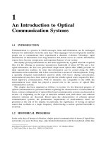
In Fig. 2.3,
^
r
1
and
^
r
2
are, respectively, the amplitude reflection coefficients of the input
(left) and output (right) mirrors. Similarly,
^
t
1
and
^
t
2
represent the amplitude transmission
coefficients of the mirrors. Suppose an incident wave with complex propagation constant k
0
enters the etalon from z ¼ 0. After a series of parallel reflections, the total transmitted wave
at the output plane ðz ¼ LÞ becomes [5]
E
o
¼ E
i
^
t
1
^
t
2
e
jk
0
L
Â
1 þ
^
r
1
^
r
2
e
2jk
0
L
þ
^
r
2
1
^
r
2
2
e
4jk
0
L
þ
Ã
ð2:39Þ
Using an infinite sum for a geometric progression (GP) series, the above equation becomes
E
o
¼
^
t
1
^
t
2
e
jk
0
L
1
^
r
1
^
r
2
e
2jk
0
L
E
i
ð2:40Þ
By expanding the propagation constant k
0
as in eqn (2.23), eqn (2.40) can also be expressed
as
E
o
¼ E
i
^
t
1
^
t
2
e
jðkþÁkÞL
e
net
L
1
^
r
1
^
r
2
e
2jðkþÁkÞL
e
net
L
!
ð2:41Þ
Figure 2.3 A simplified Fabry–Perot cavity.
BASIC PRINCIPLES OF SEMICONDUCTOR LASERS
41
Where
net
is the net loss. When
net
> 0 and the denominator of the above equation
becomes very small such that the square bracket term is larger than unity, amplification will
occur. To obtain the self-sustained oscillation, the denominator of the above equation must
be zero, i.e.
^
r
1
^
r
2
e
2jk
0
L
¼ 1 ð2:42Þ
This is the threshold condition of a FP laser as the ratio E
o
=E
i
becomes infinite. Physically,
this corresponds to a finite transmitted wave at the output with zero incident wave. With the
amplitude and the phase term separated, one will have
^
r
1
^
r
2
e
net
L
¼ 1 ð2:43Þ
and
2ðk þ ÁkÞL ¼ 2mp ð2:44Þ
Equation (2.43) represents a case in which a wave making a round trip inside the resonator
will return with the same amplitude at the same plane. Similarly, the phase change after a
roundtrip must be an integer multiple of 2 so as to maintain a constructive phase
interference. By rearranging eqn (2.43) and (2.24), the threshold gain of the FP laser
becomes
th
¼
0
þ
2
L
ln
1
^
r
1
^
r
2
with g ¼
th
ð2:45Þ
where
m
¼
1
L
ln
1
^
r
1
^
r
2
ð2:46Þ
is the amplitude mirror loss which accounts for the radiation escaping from the FP cavity
due to finite facet reflections. Hence, the threshold gains of FP semiconductor lasers can be
determined once the physical structures are known.
From eqn (2.44), one can determine the lasing frequency. Due to the dispersive properties
shown in section 2.2, the frequency-dependent propagation constant (k þ Ák) is replaced by
a group refractive index, n
g
such that
Reðk
0
Þ¼k
0
n
g
¼ k
0
c=v
g
ð2:47Þ
where k
0
is the free space propagation constant. Replacing k
0
with 2pf =c and rearranging
eqn (2.44), the cavity resonance frequency f
m
becomes
f
m
¼
mc
2n
g
L
ð2:48Þ
where m is an arbitrary integer. When m increases, it can be seen that there is an infinite
number of longitudinal modes. In practice, however, the number of longitudinal modes
42
PRINCIPLES OF DISTRIBUTED FEEDBACK SEMICONDUCTOR LASER DIODES
depends on the width of the material gain spectrum. From the equation shown above, it can
also be confirmed that the longitudinal mode spacing is that shown in eqn (1.25) in Chapter 1.
The gain values of all probable modes increase with pumping until the threshold condition is
finally attained. The mode having the minimum threshold gain becomes the lasing mode
whilst others become non-lasing side modes. After the threshold condition is reached, the
laser gain spectrum does not clamp to a fixed value as in gaseous lasers. Instead, the lasing
gain spectrum keeps changing with the biasing current. Such an inhomogenous broadening
effect becomes so complicated that multi-mode oscillation and mode hopping become
common in FP semiconductor lasers.
The lasing spectrum and the spectral properties of the FP laser cavity are important in the
field of semiconductor lasers, since other semiconductor lasers resemble the basic FP design.
Simplicity may be an advantage for FP lasers, however, due to broad and unstable spectral
characteristics, they have limited application in coherent optical communication systems in
which a single longitudinal mode is a requirement.
2.3.3 Structural Improvements in Semiconductor Lasers
In section 2.3.1, the condition of population inversion in a heavily doped p–n junction (or
diode) was discussed. The so-called homojunction is characterised by having a single type of
material found across the p–n junction. When a forward bias voltage is applied across the
junction, the contact potential between the p and n regions is lowered. With the energy gap
remaining constant throughout the junction, the majority of carriers tend to diffuse across the
junction easily. As a result, carrier recombination along the p–n junction becomes less
efficient. Typical current density required to achieve lasing in this early diode is of the order
of 10
5
Acm
2
[6]. With such a high current density, continuous wave (CW) operation
at room temperature is impossible. Pulse mode operation is allowed at extremely low
temperature only. With such a low efficiency and high threshold current, the homojunction
structure has been replaced by more effective structures.
(a) Improvements in transverse carrier confinement
In 1963, it was discovered that the threshold current of semiconductor lasers could be
reduced significantly if carriers were confined along the active region. A three-layer
structure, which consisted of a thin layer of lower energy gap material sandwiched between
two layers of higher energy gap materials, was proposed. However, it was not until 1969
when the liquid phase epitaxy (LPE) growth of AlGaAs on a GaAs homojunction became
available. Since two different materials were involved, an additional energy barrier was
formed alongside the homogeneous p–n junction. As a result, the chance of carrier diffusion
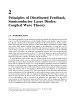
was reduced. The name single heterostructure was given [3] and is shown in Fig. 2.4(a).
Apart from the difference in energy gaps, the p-GaAs active layer has a higher refractive
index than the n-region. So, with the p-AlGaAs cladding having a considerably lower
refractive index, an asymmetric three-layer waveguide was formed within the single
heterostructure and the highest refractive index was found along the active region. The
asymmetric waveguide confined the optical intensity largely to the active region and so
the optical loss due to evanescent mode propagation was reduced. However, the best room
BASIC PRINCIPLES OF SEMICONDUCTOR LASERS
43
temperature threshold current density for the single heterostructure device is still too high
for CW operation (a typical value would be 8.6 kA cm
2
). Nevertheless, it is a great
improvement on the homostructure.
The establishment of CW operation at room temperature was finally achieved in the
1970s. As shown in Fig. 2.5, the thin active layer is now sandwiched between two layers of
higher energy gap material, and hence a double heterostructure is formed. Along the
boundary where two different materials are used, an energy barrier is formed. Carriers find it
so difficult to diffuse across the active region that they are trapped. By using a higher
refractive index material at the centre, photons are also confined in a similar way. This type
of structure is known as the separate confinement heterostructure (SCH). The combined
effects in carrier and optical confinement help bring the threshold current density down to
approximately 1.6 kA cm
2
. Operation at CW becomes feasible provided that the laser itself
is mounted on a suitable heat sink.
(b) Improvements in lateral carrier confinement
Continuous wave operation at room temperature is a significant achievement and now the
double heterostructure design is more or less standard. So far, the structures we have
Figure 2.4 Schematic illustration of a single heterojunction [4]. (a) Typical energy level diagram at
equilibrium without biasing voltage; (b) the same heterojunction under strong forward bias voltage.
Figure 2.5 Schematic illustration of a double heterojunction [4]. (a) Typical energy level diagram at
equilibrium without bias voltage; (b) under strong bias voltage.
44
PRINCIPLES OF DISTRIBUTED FEEDBACK SEMICONDUCTOR LASER DIODES
discussed belong to the broad-strip laser family since they do not incorporate any
mechanism for the lateral (parallel to the junction plane) confinement of the injected current
or the optical mode. By adopting a strip-geometry, carriers are injected over a narrow central
region using a strip contact. With carrier recombination restricted to the narrow strip (typical
width ranging from 1 to 10 mm), the threshold current is reduced significantly. Such lasers
are referred to as gain-guided because it is the lateral variation of the optical gain that
confines the optical mode to the strip vicinity. Lasers in which optical modes are confined
because of lateral variations of refractive index are known as index-guided lasers.
Comparatively, gain-guided lasers are simple to make, but their weak optical confinement
limits the beam quality [5]. Moreover, it is difficult to obtain a stable output in single
longitudinal mode. As a result, the index-guiding mechanism has become the mainstream in
semiconductor laser development and a large number of index-guided structures have been
proposed in the past decade. Basically, a lateral variation of refractive indices is used to
confine the optical energy. Various index-guided structures like the buried heterostructure
(BH), channelled substrate planar (CSP), buried crescent (BC), ridge waveguide (RW) and
dual-channel planar buried heterostructure (DCPBH) have been used. A survey of recent
research will reveal many other types of laser, but basically they are alternatives of these
basic structural designs. The structural improvement in the development of semiconductor
lasers has reduced the threshold current density whilst CW single transverse mode operation
has become feasible.
2.3.4 Material Gain in Semiconductor Lasers
Suppose a medium having complex permittivity "
0
is used to build an infinitely long
waveguide and an input signal is injected into it. After travelling a distance of L, the power
gain of the signal can be defined by an amplifying term, G, such that
G ¼ e
ðg
loss
ÞL
ð2:49Þ
where g is the material gain (or the power gain coefficient) and
loss
is the internal cavity
loss. It is important that ðg
loss
Þ > 0 for an amplified signal.
In an index-guided semiconductor laser, the refractive index of the active region ðn
1
Þ is
higher than the surrounding cladding ðn
2
Þ so that a dielectric waveguide is formed. In
practice, however, the dielectric waveguide formed is far from ideal. Under the weakly
guiding condition where ðn
1
n
2
Þn
1
, some energy leaks out into the cladding as a result
of the evanescent field. To take into account the power leakage, a weighting factor is
introduced into eqn (2.49) such that
G ¼ e
ðg
a
Þð1Þ
c
þ
sca
½L
ð2:50Þ
where
a
and
c
are the absorption losses of the active and cladding layers respectively, and
sca
is the scattering loss at the heterostructure interface. The weighting factor , known as
the optical confinement factor, defines the ratio of the optical power confined in the active
region to the total optical power flowing across the structure.
In order to determine the optical gain, various approaches have been used. In this section,
a phenomenological approach [6] will be introduced, whilst another approach using
BASIC PRINCIPLES OF SEMICONDUCTOR LASERS
45
Einstein’s coefficients [7] will be discussed in the next section. The phenomenological
approach is based on experimental observations that the peak material gain varies almost
linearly with the injected carrier concentration. Such an observation leads to a linear
approximation [8] of
g
peak
¼ A
0
ðN N
0
Þð2:51Þ
where A
0
is the differential gain and N
0
is the carrier concentration at zero material gain,
commonly known as the transparency carrier concentration. The above relation gives only a
reasonable approximation in a small biasing range when the carrier concentration is
comparable to the transparency carrier concentration. The range of accuracy is extended by
adopting a parabolic model [9] such that
g
peak
¼ aN
2
þ bN þ c ð2:52Þ
where a, b and c are constants determined by fitting the available exact solutions using the
least squares technique.
Due to the dispersive properties of the semiconductor, the actual material gain is also
affected by the optical frequency f, and hence the wavelength . So far, the value of gain has
been assumed to be at the resonant frequency, however, if the optical frequency is tuned
away from the resonant peak, the exact value of gain becomes different from that of g
peak
.
Based on experimental observation, Westbrook [10] extended the linear peak gain model
further, such that
gðN;Þ¼A
0
ðN N
0
ÞA
1
0
A
2
N N
0
ðÞðÞ½
2
ð2:53Þ
where
0
is the wavelength of the peak gain at transparency gain (i.e. g ¼ 0) and A
1
governs
the base width of the gain spectrum. The wavelength shifting coefficient A
2
takes into
account the change of the peak wavelength with respect to the carrier concentration. Notice
that the negative sign in front of A
2
indicates a negative wavelength shift of peak gain
wavelength.
In semiconductor lasers, energy enters in the form of an external biasing current. In
determining the material gain, one must determine the relationship between the carrier
concentration N and the injection current I. This is accomplished through the carrier rate
equation that includes the generation and decay carriers found in the active region. In its
general form, the equation is given as [4,11]
@N
@t
¼
I
qV
RðNÞ
v
g
gðN;ÞS
1 þ "S
þ Dðr
2
NÞð2:54Þ
where q is the electronic charge and V ¼ dwL is the volume of the active layer with d, w and
L being the thickness, the width and the length of the active layer, respectively, I is the
injection current, R(N) is the total (i.e. both radiative and non-radiative) carrier
recombination process, the term v
g
gðN;ÞS=ð1 þ "SÞ shown in the above equation takes
into account the carrier loss as a result of stimulated emission. Here, v
g
is the group velocity
and S is the photon density of the lasing mode. The effect of photon non-linearity is included
46
PRINCIPLES OF DISTRIBUTED FEEDBACK SEMICONDUCTOR LASER DIODES
in the non-linear coefficient ". In the above equation, the final term Dðr
2
NÞ represents the
carrier diffusion with D representing the diffusion coefficient.
In RðNÞ shown in equation (2.54), non-radiative carrier recombination implies those
processes will not generate any photons. For semiconductor lasers operating at shorter
wavelengths ð<1 mmÞ, the effects of non-radiative recombination are small. However,
non-radiative recombination becomes more important in long-wavelength semiconductor
lasers. In quaternary InGaAsP materials operating in the 1.30 and 1.55 mm regions, the total
carrier recombination rate can be written as
RðNÞ¼
N
þ BN
2
þ CN
3
ð2:55Þ
where is the linear recombination lifetime, B is the radiative spontaneous emission
coefficient and C is the Auger recombination coefficient. The linear recombination lifetime
includes recombination at defects or surface recombination at the laser facet. With
improvement in fabrication techniques, the number of defects and the chances of surface
recombination have been reduced significantly. In long-wavelength semiconductor lasers,
the cubic term CN
3
takes into account the non-radiative Auger recombination process. Due
to the Coulomb interaction between carriers of the same energy band, each Auger
recombination involves four carriers. According to the origins of these carriers, the Auger
recombination is classified into band-to-band, photon-assisted and trap-assisted processes.
Details on different types of Auger processes are clearly beyond the scope of the present
book, though the interested reader may refer to reference [4]. Some typical values of , B
and C for the quaternary III–V materials at 1.30 and 1.55 mm are listed in Table 2.1. Based
on the simplified carrier rate equation, all of these parameters can be measured simply, as
explained in a paper by Chu and Ghafouri-Shiraz [12].
In an index-guided semiconductor laser where the active layer width and thickness are
small compared to the carrier diffusion length of 1–3 mm, the diffusion effect becomes of
Table 2.1 Coefficients for the total recombination of quaternary materials at 1.3 mm and 1.55 mm
(after [4])
In
1x
Ga
x
As
y
P
1y
at ¼ 1:30 mm with y ¼ 0:61, x ¼ 0:28 at T ¼ 300 K
¼ 10 ns
B ¼ 1:2 10
10
cm
3
s
1
C ¼ 1:5 10
29
cm
6
s
1
In
1x
Ga
x
As
y
P
1y
at ¼ 1:55 mm with y ¼ 0:90, x ¼ 0:42 at T ¼ 300 K
¼ 4ns
B ¼ 1:0 10
10
cm
3
s
1
C ¼ 3:0 10
29
cm
6
s
1
BASIC PRINCIPLES OF SEMICONDUCTOR LASERS
47
secondary importance and can be neglected hereafter. At the lasing threshold condition, the
semiconductor laser begins to lase. With @N=@t ¼ 0, the steady state solution of the carrier
rate equation becomes
I
th
¼ qV RðN
th
Þ=
i
ð2:56Þ
where I
th
is the threshold current and N
th
is the threshold carrier density. The internal
quantum efficiency
i
gives the ratio of the radiative recombination to the total carrier
recombination. In deriving the above equation, S is assumed to be zero at the lasing
threshold condition. Sometimes, rather than the threshold current, a nominal threshold
current density J
th
(in A m
2
) is used which relates to the threshold current I
th
as
I
th
d
V
¼ J
th
ð2:57Þ
In semiconductors, any change in material gain is accompanied by a change in refractive
index as a result of the Kramer–Kroenig relationship [1]. Any change in carrier density will
induce changes in the refractive index [13,14] as
nðNÞ¼n
ini
þ
dn
dN
N ð2:58Þ
where n
ini
is the refractive index of the semiconductor when no current is injected and
dn=dN is the differential index of the semiconductor. It should be noted that the value of
dn=dN is usually negative. The refractive index becomes smaller as the injection current
increases. As we will discuss in a later chapter, any variation in carrier density will affect the
spectral behaviour of the laser since the lasing wavelength is so sensitive to variations in
refractive index.
Both the Fermi–Dirac distribution and the material gain are found to be sensitive to
temperature change. In practice, the operating temperature of semiconductor lasers is
usually stabilised by a temperature control unit. However, it is also known that the change in
optical gain due to the variation of injected carrier is more significant than that due to
changes in temperature [15]. As a result, the temperature dependence of the material gain
has been neglected in the analysis.
2.3.5 Total Radiative Recombination Rate in Semiconductors
The theory for all classes of laser can also be represented by the Einstein relation for
absorption, spontaneous emission and stimulated emission rates. In semiconductors, optical
transitions are between energy bands whilst other laser transitions are between discrete
energy levels. Nevertheless, the Einstein relations are still applicable. The major difference
between various material systems is contained in the Einstein coefficient (or transition
probabilities) which can only be determined by quantum mechanics. Transitions between
any pair of discrete energy levels are separated by hf (or E
21
). The gain coefficient gðE
21
Þ
and emission rates r
spon
ðE
21
Þ and r
rstim
ðE
21
Þ are related to one another [3,7] by
gðE
21
Þ¼
h
3
c
2
8pn
2
g
E
2
21
r
stim
ðE
21
Þð2:59Þ
r
spon
ðE
21
Þ¼
8pn
2
g
E
2
21
h
3
c
2
g
21
ðE
21
Þ
f
c
E
2
ðÞ1 f
v
E
1
ðÞ½
f
c
E
2
ðÞf
v
E
1
ðÞ
ð2:60Þ
48
PRINCIPLES OF DISTRIBUTED FEEDBACK SEMICONDUCTOR LASER DIODES
and
r
stim
ðE
21
Þ¼ 1
1
kT
e
E
21
E
Fc
E
Fv
ðÞ½
r
spon
ðE
21
Þð2:61Þ
where h is Planck’s constant, k is the Boltzmann constant, c is the free space velocity, n
g
is
the group refractive index, f
c
ðE
2
Þ and f
v
ðE
1
Þ are occupation probabilities of electrons in the
conduction and valence bands. E
Fc
and E
Fv
being the quasi-Fermi levels. It should be noted
that the unit of the gain coefficient is cm
1
whilst the units of the emission rate r
spon
and r
stim
are number of photons per unit volume per second per energy interval.
The expressions from eqns (2.59) to (2.61) demonstrate how gðE
21
Þ, r
spon
ðE
21
Þ and
r
stim
ðE
21
Þ are related to one another. To evaluate these expressions, one parameter, such as
the spontaneous emission rate r
spon
ðE
21
Þ, must be obtained experimentally. Alternatively,
they are all related by the Einstein coefficients such that
gðE
21
Þ¼B
21
f
c
ðE
2
Þf
v
ðE
1
Þ½n
g
=c ð2:62Þ
r
spon
E
21
ðÞ¼A
21
f
c
E
2
ðÞ1 f
v
E
1
ðÞ½ ð2:63Þ
r
stim
E
21
ðÞ¼A
21
f
c
E
1
ðÞf
v
E
1
ðÞ½ ð2:64Þ
with
A
21
¼ B
21
8pn
3
g
E
2
21
h
3
c
3
ð2:65Þ
at thermal equilibrium. With a known doping concentration, the unknown parameters g, r
spon
and r
stim
in eqns (2.62) to (2.64) can then be fixed after determining either A
21
or B
21
.
Without any preference, B
21
is chosen to be the key parameter. As expected, the
coefficient B
21
takes into account the interaction between electrons and holes in the presence
of electromagnetic radiation. In order to understand the interaction between them, quantum
mechanics should be used. Rather than going through the lengthy analysis, some important
results will be shown. Starting with the time-dependent Schro
¨
dinger equation, coefficient
B
21
is given as [3]
B
21
¼
q
2
h
2m
2
0
"
0
n
2
g
E
21
M
21
jj
ð2:66Þ
so that
A
21
¼
4p n
g
qE
21
m
2
0
"
0
h
2
c
3
M
21
jj
ð2:67Þ
with "
0
as the free space permittivity, q the electronic charge, m
0
the mass of an electron and
M
21
the momentum matrix between the initial (subscript 2) and final (subscript 1) electron
state.
With the actual transition involving various energy states between the conduction band
and the valence band of the semiconductor, the analysis will not be complete without the
BASIC PRINCIPLES OF SEMICONDUCTOR LASERS
49