Tài liệu Nhiều giao thức truy cập đối với truyền thông di động P10 doc
Bạn đang xem bản rút gọn của tài liệu. Xem và tải ngay bản đầy đủ của tài liệu tại đây (284.49 KB, 41 trang )
Multiple Access Protocols for Mobile Communications: GPRS, UMTS and Beyond
Alex Brand, Hamid Aghvami
Copyright
2002 John Wiley & Sons Ltd
ISBNs: 0-471-49877-7 (Hardback); 0-470-84622-4 (Electronic)
10
PACKET ACCESS IN UTRA FDD
AND UTRA TDD
In this chapter, first a brief introduction to UMTS Terrestrial Radio Access (UTRA)
matters is provided, such as fundamental radio access network concepts, basics of, for
example, the physical and the MAC layer, and the types of channels defined (namely
logical, transport and physical channels). This is followed by a discussion of certain
UTRA FDD features, such as soft handover, fast power control and compressed mode
operation. The main focus is on the mechanisms that are available for packet access on
UTRA FDD and UTRA TDD air interfaces, as provided by release 1999 of the 3GPP
specifications. Improvements being considered for further releases, currently mostly dealt
with in 3GPP under the heading of High Speed Downlink Packet Access (HSDPA), are
also discussed.
For more general information on UMTS, the reader is referred to dedicated texts such
as Reference [86].
10.1 UTRAN and Radio Interface Protocol Architecture
10.1.1 UTRAN Architecture
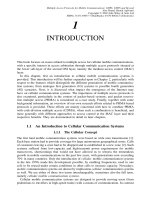
The UMTS terrestrial radio access network (UTRAN) consists of one or more Radio
Network Subsystems (RNS), which in turn are composed of a Radio Network Controller
(RNC) and multiple base stations. In UMTS terminology, base stations are referred to as
node B ; in the following, both terms will be used. A single node B may serve one or
more cells (e.g. different sectors served from one site). A node B is connected to its RNC
via the I
ub
interface. The RNC is said to be the Controlling RNC (CRNC) of that node B.
The RNC is connected to the Core Network (CN) via the I
u
interface (see Figure 10.1).
To be precise, two variants of the latter are discerned, namely I
u
-CS, which provides the
connection to the circuit-switched core network (i.e. to an MSC), and I
u
-PS, providing the
connection to the packet-switched core network (i.e. to an SGSN). Equivalent interfaces
in GSM are the A
bis
interface between a BTS and a BSC, the A interface between BSC
and MSC, and the G
b
interface between BSC and SGSN.
Compared to GSM, UTRA FDD supports two new handover types, namely soft
handover and softer handover. In both cases, communication between a mobile terminal
and the network takes place over two (or more) air interface channels concurrently.
With softer handover, the two channels are associated with two different sectors served
350
10 PACKET ACCESS IN UTRA FDD AND UTRA TDD
U
u
I
ub
I
ur
Node B
Node B
Node B
Node B
RNC
RNC
I
u
-PS
I
u
-CS
MSC/
VLR
SGSN
RNS
RNS
CN
UE
Figure 10.1 The UTRAN architecture
by the same node B, which has only ‘local’ implications not affecting the fundamental
UTRAN architecture. During soft handover, instead, the mobile terminal is connected to
the network via multiple node Bs, which may not all be controlled by the same RNC. In
this case, a means for communication between RNCs is required, which is the main reason
why a new interface is defined in UMTS to connect two RNCs, namely the I
ur
interface.
Being connected to multiple cells served by different antenna sites allows one to benefit
from so-called macro-diversity, a technique which improves the transmission quality and
helps, together with fast power control, to combat the near-far problem typical of CDMA
systems. One RNC, the Serving RNC (SRNC), must ensure that the right signals are sent
by the relevant node Bs on the downlink, and must combine the signals from multiple
node Bs on the uplink in order to deliver only one signal stream onwards to the core
network. If node Bs involved in the soft handover are controlled by other RNCs, then
these are referred to as Drift RNC (DRNC). For further information on this subject, the
reader is referred to 3GPP technical report 25.832 [276] on handover manifestations.
The UTRAN architecture is shown in Figure 10.1. This figure shows also the so-called
User Equipment (UE), which is the combination of a mobile terminal or Mobile Equipment
(ME) with a Universal Subscriber Identity Module (USIM), the UMTS version of the well
know GSM SIM. The radio interface, that is the interface between UE and node B, is
denoted U
u
. In the following, we stick to the terminology known from GSM, i.e. we
continue to refer to a UE as a mobile terminal or mobile station (MS).
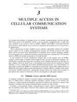
10.1.2 Radio Interface Protocol Architecture
As in GSM, three layers are relevant for the radio interface, namely the physical layer
(layer 1 or PHY), the data link layer (layer 2) and the network layer (layer 3), the last
two featuring several sub-layers. However, in contrast to the rather confusing situation in
GSM depicted in Figure 4.3, the radio interface protocol architecture has been rationalised
in UMTS — at least as far as terminology is concerned. The lowest three (sub-)layers
10.1 UTRAN AND RADIO INTERFACE PROTOCOL ARCHITECTURE
351
are uniformly referred to as physical layer, MAC, and RLC, the last two being sub-
layers of layer 2. In the so-called control-plane or C-plane dealing with signalling, the
Radio Resource Control (RRC) sits on top of the RLC. The RRC is the lowest sub-
layer of layer 3, and is the only sub-layer of layer 3 fully associated with and terminated
in the UTRAN. In the user-plane or U-plane, additional sub-layers may be required
at layer 2 depending on the services supported, namely the Packet Data Convergence
Protocol (PDCP) in the ‘packet domain’, which replaces the LLC and the SNDCP known
from GPRS, and the Broadcast/Multicast Control Protocol (BMC). The UMTS protocol
architecture is illustrated in Figure 10.2. As shown, the PHY offers its services to the
MAC in the shape of transport channels, and the MAC to the RLC in that of logical
channels. A transport channel is characterised by how the information is transferred over
the radio interface, while a logical channel by the type of information transferred. This
distinction is not made in GSM, where the PHY offers logical channels to the upper
layers.
Layer 2 provides radio bearers to higher layers. The C-plane radio bearers provided by
the RLC to the RRC are signalling radio bearers. The RRC interfaces not only the RLC,
but also all other layers below it for control purposes, quite like RR in GSM. For more
information on the radio interface protocol architecture, the reader is referred to 3GPP
technical specification 25.301 [277].
One reason why the GSM protocol architecture is somewhat confusing is that the system
was designed initially for circuit-switched services, in particular voice, so MAC and RLC
with associated header overheads were not really required at first and only added later for
GPRS. In UMTS instead, for consistency, MAC and RLC are always defined, but they
can both be operated in different modes, depending on what MAC and RLC features are
U-plane radio bearers
PHY
RLC
MAC
RRC
BMC
PDCP
Signalling radio bearers
Control-plane
User-plane
Transport channels
Logical channels
Control
L1
L2
L3
Figure 10.2 Protocol architecture on the radio interface
352
10 PACKET ACCESS IN UTRA FDD AND UTRA TDD
required for a specific service. For instance, when no MAC header is required, the MAC
operates in transparent mode.
Before delving into some of the details pertaining to PHY, MAC, and RLC, let us
reiterate a definition hidden in a footnote in Chapter 4 and add a new one, both listed in
Reference [213]. A Protocol Data Unit (PDU) of protocol X is the unit of data specified
at the X-protocol layer consisting of X-protocol control information and possibly X-
protocol layer user data. A Service Data Unit (SDU) of protocol X is a certain amount
of information whose identity is preserved when transferred between peer (X + 1)-layer
entities and which is not interpreted by the supporting X-layer entities. In simple terms,
taking as an example layer X to be the MAC and X + 1 the RLC, a MAC PDU is
composed of a MAC header and an RLC PDU. From a MAC perspective, the RLC PDU
represents the MAC SDU.
10.1.3 3GPP Document Structure for UTRAN
The 3GPP Technical Specifications (TS) relevant for UTRAN are the 25-series of spec-
ifications. Documents numbered 25.1xy deal with radio frequency matters, 25.2xy with
the physical layer of the air interface, 25.3xy with radio layers 2 and 3 (i.e. MAC, RLC
and RRC) and 25.4xy with the radio access network architecture. Additional information
can be found in Technical Reports (TR) numbered 25.8xy and 25.9xy. The information
presented in the following was mostly derived from 25.2xy and 25.3xy documents, in
some cases complemented by 25.8xy and 25.9xy reports, as referenced in the text. For
further information on the 3GPP document structure, refer also to the appendix.
10.1.4 Physical Layer Basics
10.1.4.1 Physical Layer Functions
The physical layer performs numerous functions as listed in TS 25.201 [278]. Among
them are:
• macro-diversity distribution/combining and soft handover execution;
• FEC encoding/decoding of transport channels, error detection on transport channels
and indication of errors to higher layers;
• multiplexing of transport channels onto so-called Coded Composite Transport CHan-
nels (CCTrCH) at the transmit side, demultiplexing from CCTrCHs to transport chan-
nels on the receive side;
• mapping between CCTrCHs and physical channels;
• modulation/spreading and demodulation/despreading of physical channels;
• frequency and time synchronisation, the latter on the level of chips, bits, slots, and
frames;
• measurement of radio characteristics including FER, SIR, interference power, etc.,
which are then reported to higher layers; and
• inner or closed-loop power control.
10.1 UTRAN AND RADIO INTERFACE PROTOCOL ARCHITECTURE
353
10.1.4.2 Basic Multiple Access Scheme and Physical Channels
The basic multiple access scheme employed in UTRA is direct-sequence code-division
multiple access (DS-CDMA), with information spread over approximately 5 MHz of
bandwidth, which is why this scheme is also referred to as wideband CDMA (WCDMA).
Two duplex modes are supported, namely frequency-division duplex (FDD) and time-
division duplex (TDD), the basic multiple access scheme of the latter also referred to
as TD/CDMA. In both cases, a 10 ms radio frame is divided into 15 regular slots,
at a chip-rate of 3.84 Mchip/s each slot measuring 2560 chips. The UTRA modulation
scheme is quadrature phase shift keying (QPSK). In UTRA FDD, a double-length (i.e.
5120 chips) access slot format is also defined, with 15 access slots fitting into two radio
frames.
The physical layer makes use of physical channels for the delivery of data over the air
interface. In FDD mode, a physical channel is characterised by the code, the frequency
and in the uplink also the relative phase, either I for in-phase,orQforquadrature-phase.
In TDD mode, in addition, the physical channel is also characterised by the time-slot.
UTRA supports variable Spreading Factors (SF):
• UTRA FDD from 256 to 4 on the uplink and from 512 to 4 on the downlink;
• UTRATDDfrom16to1oneitherlink.
Accordingly, the information rate of the channel is also variable.
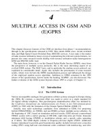
Signals are first spread using channelisation codes, after which a scrambling code is
applied at the same chip-rate as the channelisation code; hence scrambling does not alter
the signal bandwidth. This is illustrated in Figure 10.3. Channelisation codes are used to
separate channels from the same source (i.e. on the downlink different channels in one
sector or cell, on the uplink different dedicated channels sent by one mobile terminal).
Scrambling codes are used to separate signals from different sources.
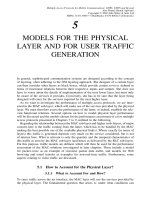
The channelisation codes are based on the Orthogonal Variable Spreading Factor
(OVSF) technique, which allows mutually orthogonal codes to be chosen from a code-
tree, even when codes for different spreading factors are used simultaneously. It indeed
makes sense to invest some effort in choosing orthogonal codes to separate channels from
the same source. In ‘benign’ propagation conditions, in fact, this orthogonality is largely
maintained at the receiving side. The number of codes available per tree is fairly limited
though; it is equal to the spreading factor if all codes use the same spreading factor. An
example with spreading factors from one (root of the tree) to eight is shown in Figure 10.4.
The leaves of the tree at SF = 8 represent the available codes, if only SF = 8isusedina
cell. However, if a code at SF = 2 is assigned, then the tree is essentially pruned at that
Channelisation
code
Scrambling
code
Data
Bit rate Chip rate Chip rate
Figure 10.3 SpreadingandscramblinginUTRA
354
10 PACKET ACCESS IN UTRA FDD AND UTRA TDD
'Pruned' sub-tree
Assigned code at SF = 2
Root of tree
Cannot be used
when code below
root assigned
SF = 1
SF = 2
SF = 4
SF = 8
Figure 10.4 Example of an OVSF code tree
code, codes with higher spreading factors in the sub-tree below that specific code are not
available anymore. More precisely, a code can be assigned to a mobile terminal if and
only if no other code on the path from that code to the root of the tree or in the sub-tree
below that code is assigned [279].
Without introducing special measures such as very tight synchronisation between
different users, the orthogonality of signals sent by different sources would be lost at
the receiving side even if orthogonal codes were selected at the transmitting side. This is
why rather than orthogonality, other criteria such as the number of available codes and
their auto-correlation properties were more important for the choice of suitable scrambling
codes. In UTRA FDD, there are two types of scrambling codes, Gold codes with a 10 ms
period (i.e. 38 400 chips) and so-called extended S(2) codes with a period of 256 chips,
the latter optional and only applicable on the uplink. In UTRA TDD, the code-length of
scrambling codes is 16.
For details on modulation and spreading, refer to TS 25.213 [280] (for FDD) and to
TS 25.223 [281] (for TDD).
10.1.4.3 Transport Channels offered by the Physical Layer to the MAC
Various types of transport channels are offered by the PHY to the MAC. Transport chan-
nels are unidirectional channels. They can be classified into two groups, namely:
• common transport channels, where there is a need for inband identification of mobile
terminals if a particular terminal is to be addressed; and
• dedicated transport channels, where, by virtue of a channel being dedicated to a
particular communication, the terminal is identified by the physical channel it uses.
Common transport channels supported in R99 are:
• the Random Access CHannel (RACH) on the uplink;
10.1 UTRAN AND RADIO INTERFACE PROTOCOL ARCHITECTURE
355
• the Forward Access CHannel (FACH) on the downlink;
• the Downlink Shared CHannel (DSCH);
• the Common Packet CHannel (CPCH) on the uplink, only defined for UTRA FDD;
• the Uplink Shared CHannel (USCH), only defined for UTRA TDD;
• the Broadcast CHannel (BCH) on the downlink; and
• the Paging CHannel (PCH), also on the downlink.
There is only one type of dedicated transport channel defined in R99, namely the
Dedicated CHannel (DCH).
10.1.4.4 Transport Channel Characteristics
The basic information unit delivered by the MAC on a transport channel to the physical
layer is a transport block. Every so-called Transmission Time Interval (TTI), the MAC
delivers either one or a set of transport blocks to the PHY for a given transport channel.
Within a transport block set, all transport blocks are equally sized (but the block size
can change from TTI to TTI). The TTI can assume integer multiples of the minimum
interleaving period, which is 10 ms. More precisely, possible values are 10, 20, 40 or
80 ms. The TTI determines the interleaving depth, hence robustness against fading can
be adjusted according to the delay constraints of the service to be supported.
The characteristics of a given transport channel are determined by its transport format,
with attributes such as the transport block size, the number of transport blocks in a
transport block set, the TTI, the error protection scheme to be applied (type and rate of
channel coding), and the size of the CRC. Transport channel characteristics can be defined
in terms of a transport format set. Some of the transport format attributes, such as those
regarding the error protection scheme, must be the same within a transport format set.
However, different transport block set sizes, optionally even different transport block sizes,
can be chosen for transport formats within a transport format set. These two parameters
affect the instantaneous bit-rate, and thus provide the means for a transport channel to
support variable bit-rates. At every TTI, the MAC delivers the transport block set for a
given transport channel to the PHY with the Transport Format Indicator (TFI) as a label,
which indicates the transport format picked by the MAC from the transport format set.
Layer 1 can multiplex one or several transport channels onto a coded composite trans-
port channel, each of them with its own transport format picked from its transport format
set. However, not all possible permutations of these combinations are allowed. Rather,
only a set of authorised Transport Format Combinations (TFC) may be used so that, for
instance, the maximum instantaneous bit-rate of all transport channels added together can
be limited. On the transmit side, the physical layer builds the Transport Format Combi-
nation Identifier (TFCI) from the individual TFIs, which is then appended to the physical
control signalling. This is illustrated in Figure 10.9 provided in the next section on UTRA
FDD. By decoding the TFCI on the physical control channel, the receiving side has all the
parameters needed to decode the information on the physical data channels and deliver
them to the MAC in the format of the appropriate transport channels. In UTRA FDD, if
only a limited set of transport format combinations is used, then the receiving side may be
in a position to perform blind detection, in which case TFCI signalling may be omitted.
356
10 PACKET ACCESS IN UTRA FDD AND UTRA TDD
More details on these matters including suitable illustrations are provided in the next few
sections. Further information can also be found in TS 25.302 [282].
10.1.5 MAC Layer Basics
10.1.5.1 MAC Layer Functions
The MAC layer is specified in TS 25.321 [283]. Functions performed by the MAC include:
• the mapping between logical channels and transport channels;
• the selection of appropriate transport formats for each transport channel depending on
the instantaneous source rate;
• various types of priority handling, be this between data flows from one terminal or
from different terminals;
• the identification of mobile terminals on common transport channels; and
• the multiplexing of higher layer PDUs onto transport blocks to be delivered to the
PHY on the transmitting side and demultiplexing of these PDUs from transport blocks
delivered from the PHY on the receiving side.
Regarding the selection of appropriate transport formats (within the transport format
sets defined for each transport channel), note that the assignment of transport format
combination sets is done at layer 3. Therefore, the MAC has only a limited choice of
transport formats, namely from the permitted combinations contained in the transport
format combination set.
10.1.5.2 Logical Channels offered by the MAC to the RLC
Logical channels can be classified into two groups, namely control channels for the
transfer of C-plane information, and traffic channels for the transfer of U-plane informa-
tion. Except for the last one, the types of control channels defined for UMTS R99 will
be familiar in name from GSM:
• the Broadcast Control CHannel (BCCH), a downlink channel used for broadcasting
system control information;
• the Paging Control CHannel (PCCH), a downlink channel used to transfer paging
information, when the network does not know the MS location at cell level or when
the MS is in sleep mode;
• the Common Control CHannel (CCCH), a bi-directional channel used for transmitting
control information;
• the Dedicated Control CHannel (DCCH), a point-to-point bi-directional channel
used for the transmission of dedicated control information between an MS and the
network; and
• the SHared Channel Control CHannel (SHCCH), a bi-directional channel defined for
UTRA TDD only, which is used to transmit control information between MS and
network relating to shared uplink or downlink transport channels.
10.1 UTRAN AND RADIO INTERFACE PROTOCOL ARCHITECTURE
357
Two types of traffic channels are distinguished:
• the Dedicated Traffic CHannel (DTCH), a point-to-point uplink or downlink channel
dedicated to one MS for the transfer of user information; and
• the Common Traffic CHannel (CTCH), a point-to-multipoint unidirectional (downlink
only) channel used for the transfer of dedicated user information for all or a group of
specified mobile terminals.
It is important to note that the DTCH can be mapped onto dedicated or common
transport channels. This is owing to the distinction mentioned earlier between the type of
information transferred (as defined by the logical channel, here the DTCH) and how the
information is transferred over the radio interface at the level of transport channels.
10.1.5.3 Types of MAC Entities and MAC Modes
Three different types of MAC entities are distinguished in TS 25.321, which handle
different types of transport channels, namely:
• the MAC-b handling the BCH (hence b for broadcast), at the network side, it is situated
at the node B;
• the MAC-c/sh handling all other common (or shared) transport channels, namely the
DSCH, CPCH, FACH, PCH, RACH, and USCH; it is situated at the controlling
RNC; and
• the MAC-d handling the only dedicated transport channel defined, namely the DCH.
The MAC-d is situated at the serving RNC. When logical channels of dedicated type
are mapped onto common transport channels, then the MAC-d, which provides these
logical channels to the RLC, must interact with the MAC-c/sh, e.g. pass data to be
transmitted through common transport channels on to the MAC-c/sh.
Obviously, the mobile terminal must support all different types of MAC entities.
Certain MAC features are not always required. For instance, inband identification of
mobile terminals through a suitable identity contained in a MAC header are, with a few
exceptions, only required when a dedicated logical channel is mapped onto a common
transport channel. The case where no MAC header is required is referred to as transparent
MAC transmission in TS 25.301.
10.1.6 RLC Layer Basics
The RLC provides three types of data transfer services to higher layers, namely trans-
parent, unacknowledged, and acknowledged data transfer. In the case of transparent data
transfer, higher layer PDUs are transmitted without adding any protocol information (e.g.
RLC headers). In this transfer mode the ‘RLC barely exists’, although RLC segmentation
and reassembly functionality may be used in transparent RLC mode. Unacknowledged
data transfer means that higher layer PDUs are transmitted without guaranteeing delivery
to the peer entity. However, the RLC performs error detection and delivers only SDUs
free of transmission errors to higher layers. Finally, acknowledged data transfer implies
358
10 PACKET ACCESS IN UTRA FDD AND UTRA TDD
error-free transmission (to the extent possible within specified delay limits, etc.). This is
achieved by applying appropriate ARQ strategies.
Both RLC acknowledged mode and unacknowledged mode imply the addition of RLC
headers to higher layer SDUs.
10.2 UTRA FDD Channels and Procedures
10.2.1 Mapping between Logical Channels and Transport
Channels
All transport channels and logical channels listed in Subsections 10.1.4 and 10.1.5 respec-
tively are defined for UTRA FDD, with the exception of the USCH and the SHCCH,
which are only defined for UTRA TDD. The possible mapping between UTRA FDD
logical channels and transport channels is depicted in Figure 10.5. As pointed out in the
previous section, the DTCH can be mapped onto common or dedicated transport chan-
nels, hence onto the RACH, the CPCH, the DSCH, the FACH and the DCH (the first two
obviously only in uplink direction, the DSCH and the FACH only in downlink direction).
More than one DTCH can be mapped onto a single DCH, but different DTCHs can also be
mapped onto different DCHs, depending on how the relevant radio bearers are configured.
10.2.2 Physical Channels in UTRA FDD
AUTRAFDDphysical channel is characterised by the code, the frequency and in the
uplink also the relative phase, either I for in-phase,orQforquadrature-phase.More
precisely, the uplink modulation is a dual-channel QPSK, which means separate BPSK
modulation of different channels on I-channel and Q-channel. Downlink modulation is
‘proper’ QPSK (i.e. a single channel is modulated onto both in-phase and quadrature
phase). It means that the symbol-rate of an up- and a downlink channel at a given
spreading factor are the same, but that the downlink physical channel bit-rate is double
that of the uplink physical channel, for example 30 kbit/s as compared to 15 kbit/s at
a spreading factor of 256. As well as physical channels, there are also physical signals,
DCCH
DTCH
RACH
CPCH
DCH
BCCH
PCCH
CCCH
DCCH
DTCH
CTCH
BCH
FACH
PCH
DSCH
DCH
Logical
channels
CCCH
Transport
channels
Logical
channels
Transport
channels
UPLINK DOWNLINK
Figure 10.5 Mapping between logical and transport channels in UTRA FDD
10.2 UTRA FDD CHANNELS AND PROCEDURES
359
which do not have transport channels mapped to them. As usual, physical channels can
be categorised as either dedicated or common physical channels.
10.2.2.1 Dedicated Physical Channels
All dedicated physical channels feature a radio frame length of 10 ms, with each frame
subdivided into 15 slots. In the uplink direction, a Dedicated Physical Control CHannel
(DPCCH) carrying layer 1 control information is code-multiplexed with the Dedicated
Physical Data CHannel (DPDCH). In the downlink direction, there is effectively only
one type of downlink Dedicated Physical Channel (DPCH), onto which data generated at
layer 2 and above (i.e. the dedicated transport channel) is time-multiplexed with layer 1
control information. This is kind of similar to GSM bursts carrying layer 1 control infor-
mation in the shape of training sequences and higher layer data in the payload portion of
the burst format. With respect to the terminology used for the uplink, one could view the
downlink DPCH as a time multiplex of a downlink DPDCH and a downlink DPCCH. The
different slot formats in the uplink and downlink direction are illustrated in Figures 10.6
and 10.7 respectively.
The layer 1 control information consists of pilot bits (training sequences), TFCI bits
discussed in Subsection 10.1.4, Transmit Power Control (TPC) bits, and (in the uplink
Data
N
data
bits
1 radio frame lasting 10 ms
Pilot
N
pilot
bits
TFCl
N
TFCl
bits
FBI
N
FBI
bits
TPC
N
TPC
bits
DPDCH
DPDCH
1 slot = 2560 chips,
N
data
= 10 × 2
k
bits (with
k
= 0..6, SF = 2
8-k
)
1 slot = 2560 chips, 10 bits
Slot 0 Slot 1 Slot
i
Slot 14
Figure 10.6 Slot format and frame structure on the uplink DPDCH and DPCCH
Slot 1Slot 0 Slot i
One radio frame lasting 10 ms
Slot 14
DPDCH DPCCH DPDCH DPCCH
Data1
N
data1
bits
TPC
N
TPC
bits
TFCI
N
TFCI
bits
Data2
N
data2
bits
Pilot
N
pilot
bits
1 slot = 2560 chips, 10 × 2
k
bits (with
k
= 0..7, SF = 2
9−k
)
Figure 10.7 Slot format and frame structure for downlink DPCH
360
10 PACKET ACCESS IN UTRA FDD AND UTRA TDD
direction only) so-called feedback information bits used for closed-loop transmit diversity
(see Reference [86] for details).
In the uplink direction, the DPDCH spreading factor is variable from 256 to 4, while
that of the DPCCH is always 256, giving 10 bits per slot for physical layer overhead
at a channel bit-rate of 15 kbit/s
1
. Different slot formats are defined, on the DPDCH
specifying the spreading factor, on the DPCCH specifying how many bits are used as
pilot, TPC, TFCI and feedback bits respectively (the last two types of bits are not always
required). With single-code operation, the maximum gross data-rate (before error coding)
on the uplink DPDCH is 960 kbit/s at SF = 4.
In the downlink direction, the DPCH spreading factor is variable from 512 to 4. The
slot formats define the spreading factor, the number of DPDCH (i.e. data) bits, TPC, pilot
and TFCI bits. Some slot formats specify zero TFCI bits. With single-code operation, the
maximum gross data-rate at SF = 4 is 1920 kbit/s. Adjusted for the time-multiplexed TPC,
pilot and TFCI bits, 1872 kbit/s remain. Certain mobile terminals may support multi-code
operation (i.e. the use of multiple channelisation codes in parallel), allowing the data-rates
to be further increased. Again, refer to Figures 10.6 and 10.7 for illustrations.
10.2.2.2 Uplink Common Physical Channels
The common physical channels defined on the uplink are the Physical Random Access
CHannel (PRACH) and the Physical Common Packet CHannel (PCPCH). Not surprisingly
they are used to carry the RACH and the CPCH respectively. They are both split into
preamble parts and message parts. The preambles are 4096 chips long, fitting into access
slots with a length of 5120 chips, i.e. double the length of a normal slot (hence there
are 15 slots numbered from 0 to 14 every 20 ms or two radio frames). On the PRACH,
there is only one type of preamble, while there are two mandatory preamble types on the
PCPCH, namely the access preamble and the collision detection preamble. The message
part on the PRACH is either one or two radio frames long, on the PCPCH one or several
radio frames (up to 64). In both cases, the structure of the message part is very similar
to that of the uplink dedicated physical channels, i.e. consisting of code-multiplexed data
and control frames, the latter containing pilot and TFCI bits, in the case of the PCPCH
also TPC and feedback bits. More details are provided in the next section.
10.2.2.3 Downlink Common Physical Channels
The following downlink common physical channels and signals are defined.
• The Common Pilot CHannel (CPICH), with exactly one mandatory Primary CPICH
(P-CPICH) per cell and zero, one or several Secondary CPICH (S-CPICH). Both
CPICH types are signals at a fixed rate of 30 kbit/s (i.e. SF = 256), which carry
predefined bit sequences. The P-CPICH must be broadcast over the entire cell, whereas
the S-CPICH may also be transmitted over only a part of the cell, e.g. as a result of
the application of smart antennas.
1
For comparison, on a GSM full-rate channel, if all except the encrypted symbols in the normal burst format
shown in Figure 4.5 are taken to be physical layer overhead, an ‘overhead bit-rate’ of 8.72 kbit/s results. One
might also add the SACCH overhead, since it includes power control and timing advance information (but
not only!), resulting in a total rate of roughly 10 kbit/s. A fair comparison would also have to account for the
fact that the DPCCH is transmitted at lower power than the DPDCH, e.g. 3 dB lower for voice according to
Reference [86, Table 11.2], which halves the UTRA FDD overhead.
10.2 UTRA FDD CHANNELS AND PROCEDURES
361
• The Primary Common Control Physical CHannel (P-CCPCH), which is a fixed rate
channel (30 kbit/s, SF = 256) used to carry the BCH. This channel is not transmitted
during the first 256 chips in each (regular) slot, which are instead used for the SCH.
• The Secondary Common Control Physical CHannel (S-CCPCH), a variable rate
channel with spreading factors from 256 down to four used to carry the FACH and
the PCH.
• The Synchronisation CHannel (SCH), a downlink signal used for cell search, which
consists of two subchannels, namely the primary and the secondary SCH. They are
transmitted during the first 256 chips in each (regular) slot, i.e. when the P-CCPCH
is not transmitted.
• The Physical Downlink Shared CHannel (PDSCH) used to carry the DSCH. Unlike
the DPCH, it does not carry any layer 1 control information. Instead, this information
has to be carried by the DPCCH part of an associated downlink DPCH.
Also part of the downlink common physical channels are a number of indicator chan-
nels. Four of them provide fast downlink signalling required for the operation of the
uplink common physical channels, i.e. the PRACH and the PCPCH. They are all fixed
rate channels (SF = 256) making use of the double-length (i.e. 5120 chips or 1.33 ms)
access slot format, the first three using only the first 4096 chips of each slot, the last one
using the remaining 1024 chips, as follows.
• The Acquisition Indicator CHannel (AICH) used to carry Acquisition Indicators (AI)
responding to PRACH preambles.
• The CPCH Access Preamble Acquisition Indicator CHannel (AP-AICH) carrying
Access Preamble acquisition Indicators (API) responding to CPCH access preambles.
• The CPCH Collision Detection/Channel Assignment Indicator CHannel (CD/CA-ICH)
carrying either Collision Detection Indicators (CDI), or, if channel assignment is
used for the CPCH, Collision Detection Indicators/Collision Assignment Indicators
(CDI/CAI) in response to CPCH collision detection preambles.
• The CPCH Status Indicator CHannel (CSICH) signalling the availability of CPCHs
through Status Indicators (SI). This channel is always associated with a CPCH AP-
AICH, the AP-AICH making use of the first 4096 chips per access slot, the CSICH
of the remaining 1024 chips.
The fifth downlink indicator channel is the Paging Indicator CHannel (PICH), which is a
fixed rate channel (SF = 256) like all other indicator channels. It carries Paging Indicators
(PI), which are related to the PCH transport channel mapped onto an S-CCPCH.
10.2.2.4 Timing Relationships
On the downlink, CPICH, SCH/P-CCPCH and PDSCH have identical frame timings.
Also, the 15 double-length downlink access slots carrying the various indicator channels
used for RACH and CPCH operation are aligned in that slot 0 starts at the same time as
an even-numbered P-CCPCH frame. All other channels are not aligned. Different rules
apply for the timing offset of the different channels, with the constraint that the offset is
in integer multiples of 256 chips. Details can be found in TS 25.211 [58].
362
10 PACKET ACCESS IN UTRA FDD AND UTRA TDD
On the uplink, the transmit timing at the mobile terminals depends always on the timing
of the received signals at the terminals, which means that, unlike in GSM, there is no
timing advance. For instance, the uplink DPCCH/DPDCH frame transmission is 1024
chips delayed with respect to the received DPCH frame. The timing relationship between
PRACH and AICH, and between CPCH and the CPCH-related indicator channels are
discussed in the next section, in the context of packet transmission on the RACH and the
CPCH respectively.
10.2.3 Mapping of Transport Channels and Indicators to
Physical Channels
The physical layer offers transport channels as services to higher layers. It also offers
indicators, which are fast low-level signalling entities that can be transmitted without
relying on information blocks sent over transport channels. These indicators are either
boolean (two-valued) or three-valued. The mapping of transport channels and indicators
to physical channels is illustrated in Figure 10.8. This figure also shows physical signals,
which do not have transport channels or indicators mapped to them.
Signals
Synchronisation channel (SCH)
Common pilot channel (CPICH)
Physical channels
Dedicated physical data channel (DPDCH)
Dedicated physical control channel (DPCCH)
Physical random access channel (PRACH)
Physical common packet channel (PCPCH)
Primary common control physical channel (P-CCPCH)
Secondary common control physical channel
(S-CCPCH)
Physical downlink shared channel (PDSCH)
Acquisition indicator channel (AICH)
Access preamble acquisition indicator channel (AP-AICH)
Paging indicator channel (PICH)
CPCH status indicator channel (CSICH)
Collision-detection/channel-assignment indicator
Channel (CD/CA-ICH)
Transport
Channels
DCH
RACH
CPCH
BCH
FACH
PCH
DSCH
Indicators
AI
API
PI
SI
CDI/CAI
Figure 10.8 Mapping of transport channels and indicators to physical channels
10.2 UTRA FDD CHANNELS AND PROCEDURES
363
TFI
Transport block
TFI Transport block TFI Transport block
Higher layers
Physical layer
TFCI
DPCCH DPDCH
Transport Ch. 1 Transport Ch. 2
Transport block
Transport block
Transport Ch. 3
Transport block
Coding & multiplexing
Figure 10.9 Multiplexing of transport channels onto physical channels
Figure 10.9 illustrates the multiplexing onto DPDCH and DPCCH of transport blocks
and TFIs delivered by three transport channels at a given instant in time. Note that if,
for example, the third transport channel has double the TTI of the other two, it will only
deliver transport blocks to the PHY every second time the other two channels deliver them.
10.2.4 Power Control
It should be clear from earlier chapters that, because power is the shared resource in
a CDMA system, transmit power control is a very important aspect of such a system.
In fact, on the uplink, it is a vital feature to combat the near-far problem. Assuming
homogeneous services (i.e. all users request the same bit-rates), one strategy is to control
the transmit power in such a way that the received power levels at the base station are all
equal. Other strategies can be thought of, such as SIR-based power control and differential
power control in the case of heterogeneous services.
A rough means to control the uplink transmit power is open-loop power control.The
terminal estimates the attenuation on the radio channel by listening to a pilot or beacon
signal sent by the base station at a known power level and regulates its transmit power
according to this estimate. The problem in an FDD system is that, due to frequency
separation between the links, the uplink and downlink fast fading processes are pretty
much independent. This method is therefore not very accurate and is only applied where
closed-loop power control is not practicable, for instance on the RACH.
The solution used for instance on dedicated channels is fast closed-loop power control,
where the base station measures received SIR levels, compares them with a target level
and, based on the outcome of this comparison, orders the mobile terminals to either
increase or decrease the transmit power level. In UTRA FDD, this happens once per
slot, hence the power control rate is 1.5 kHz. This is fast enough to track pathloss and
shadowing, and even fast fading of mobiles at low to moderate speeds. Closed-loop power
364
10 PACKET ACCESS IN UTRA FDD AND UTRA TDD
control can be decomposed into outer-loop and inner-loop components. Outer-loop power
control is a slow activity consisting of adjustments in the target SIR level based on the
quality requirements and the current propagation conditions. Inner-loop power control is
the fast ordering and adjustment process carried out once per slot to meet the target SIR.
On the downlink, since there is only a single signal source in a cell, power control
is not needed to overcome the near-far problem. Instead, it is used to compensate for
fading dips lasting longer than the interleaving period (which is mainly relevant for slow
moving mobiles) and to aid mobiles at the cell edge suffering from increased intercell
interference.
10.2.5 Soft Handover
As pointed out in the previous section, being connected to more than one base station
during soft handover provides macro-diversity, which improves the transmission quality
and helps, together with fast power control, to combat the near-far problem. The idea
behind macro-diversity is as follows. If the same signal is transmitted via different prop-
agation paths, which exhibit no or little correlation, then the probability that at least one
of the paths delivers sufficient signal quality at the receiver at any given time is higher
than when only a single path is relied upon.
In the uplink direction, during soft handover, a single signal transmitted by a mobile
terminal is received by multiple base stations or node Bs. These base stations constitute
the so-called active set. The different received signal copies are combined by the SRNC.
From a terminal and interference perspective, nothing much changes with the exception
that base stations in the active set try to execute closed-loop power control independently,
which may result in the mobile terminal receiving conflicting power control commands.
In this case, power-down commands have priority, since they imply that one base station
in the active set receives the terminal’s signal at sufficient quality (and this is exactly
what is aimed for). Example results showing the benefit of soft handover for two base
stations in the active set are provided in Reference [86, p. 203]. Under the propagation
conditions considered in Reference [86], the maximum gain in terms of terminal transmit
power reduction is close to 2 dB, when the pathloss from the terminal to each of the two
base stations is equal. With increasing difference in the pathloss, the gain decreases. It
disappears completely when the pathloss difference exceeds 5 dB.
In the downlink direction, soft handover has a quite fundamental implication in that
signals directed to a single terminal in soft handover state are transmitted by multiple
base stations (i.e. again those in the active set). This will obviously lead to increased
downlink interference. Therefore, a clear trade-off exists between the positive effect of
macro-diversity and the negative effect of increased interference. The maximum net gain at
equal pathloss is 2.5 dB. At a pathloss difference of 6 dB, a net loss of 0.5 dB is incurred,
at a difference of 10 dB a loss of even 2.5 dB. This is immediately intuitive: when the
pathloss difference is large, the contribution of the ‘weaker’ base station to the received
signal power at the terminal is negligible, hence the transmit power at the stronger base
station cannot be reduced. At the same time, the signal is transmitted twice, which means
that the total transmit power and thus the interference is increased by 3 dB (assuming equal
transmit power levels). In simpler terms, the ‘weaker’ base station generates additional
interference without providing any benefits. As a consequence, therefore, soft handover
is only beneficial for a fraction of the terminal population. In practice, again according to
Reference [86], the fraction of terminals in soft handover state will be below 30–40%.