Tài liệu Multisensor thiết bị đo đạc thiết kế 6o (P9) doc
Bạn đang xem bản rút gọn của tài liệu. Xem và tải ngay bản đầy đủ của tài liệu tại đây (1.14 MB, 22 trang )
187
9
INSTRUMENTATION SYSTEM
INTEGRATION AND INTERFACES
9-0 INTRODUCTION
Technical evolution and economic influences have combined to define the integra-
tion of contemporary multisensor instrumentation systems relative to a delineation
of applications. A hierarchical instrumentation taxonomy is accordingly described
as illustrated by discrete automatic test equipment, remote measurement environ-
ments, automation system virtual instruments, and analytical instrumentation for
aiding sensed-feature understanding. The integration of each of these instrumenta-
tion categories is also defined by bus and network structures appropriate for meet-
ing application performance requirements.
Chapter highlights include the description of virtual instrument capabilities for
elevating fundamental sensor data to a higher attribution, enabling more complex
cognitive interpretation. Such attribution is then extended to analytical instrumenta-
tion employing hyperspectral sensing of multiple spatial and spectral data for im-
proved feature characterization. This is shown to be useful in advanced process
control systems for comparing product states to goal states during manufacturing
for the purpose of synthesizing compensating online quality control references.
9-1 SYSTEM INTEGRATION AND INTERFACE BUSES
Electrical measurement has been evolving for nearly two centuries since the inven-
tion of the galvanometer in 1820. Continued development has provided an expand-
ing range of sophisticated measurement, signal conditioning, analysis, and data
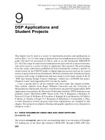
presentation capabilities with the instrumentation taxonomy, shown in Figure 9-1,
that can accommodate the comprehensive data requirements of advanced hierarchi-
cal sensor and actuator systems. Four distinct instrumentation integration structures
are defined, each of which involve different implementations for meeting their re-
Multisensor Instrumentation 6
Design. By Patrick H. Garrett
Copyright © 2002 by John Wiley & Sons, Inc.
ISBNs: 0-471-20506-0 (Print); 0-471-22155-4 (Electronic)
spective excitation and measurement applications. Examples are presented in the
sections that follow that highlight effective solutions to contemporary instrumenta-
tion challenges for each of these architectures.
The diversity of existing bus structures provides a useful delineation of capabili-
ties for instrumentation system integration. Figure 9-2 introduces basic computer
bus classifications. Level-0 traces describe intercomponent board connections that
188
INSTRUMENTATION SYSTEM INTEGRATION AND INTERFACES
FIGURE 9-1. Hierarchical instrumentation taxonomony.
are characterized by signals specific to their digital devices. Level-1 dedicated bus-
es, such as the industry standard architecture (ISA) bus, provide buffered subsystem
peripheral component interfacing, including protocols to accommodate signal prop-
agation delays. Level-2 system buses, such as the peripheral component intercon-
nect (PCI) structure detailed in Figure 9-11, offer comprehensive bus master ser-
vices, including arbitration and concurrent operation. Level-3 parallel buses enable
peripheral extensions for Level-1 buses, including the general purpose interface bus
(GPIB) and small computer systems interface (SCSI) bus. Level-4 serial buses are
the longest structures in the bus repertoire, and range from early standards such as
RS-232C to the more recent universal serial bus (USB) described in the following
section. Serial bus transmission protocols are divided into synchronous and asyn-
chronous modes, with the latter prevalent. The Level-5 video bus may be limited to
an AGP port that supports the monitor.
The GPIB bus has achieved acceptance since its introduction by Hewlett-
Packard because of its robustness for networking discrete instruments. This parallel
bus can link 15 instruments plus a controller with 16 active lines, eight for data and
eight for control, as shown in Figure 9-3. Communication control procedures initi-
ated prior to data transmission designate transmitting instruments and receiving in-
struments. Instead of address lines, there are three data-transfer and five bus man-
9-1 SYSTEM INTEGRATION AND INTERFACE BUSES
189
FIGURE 9-2. Basic computer bus classifications.
agement lines for communication utilities. When ATN is high, all instruments must
listen to the DIO lines. When ATN is low, only designated instruments can send
and receive data.
External information exchanges with the host computer for all of the instrumen-
tation architectures of Figure 9-1 can be aided by the Gigabit Ethernet, especially
when high resolution graphics are involved. The efficiency of the Gigabit Ethernet
relies upon full-duplex transmission employing all four wire pairs of common Cate-
gory 5 cable, plus enabling terminal equipment shown in Figure 9-4. Performance
is facilitated by five-level PAM coding, Trellis forward error correction, and DSP
received signal equalization. Conventional Ethernet parameters are also introduced
in the following section.
Computer-based automatic test equipment (ATE) has evolved as an effective
application of parallel buses to link modular instruments in a systematic quality
control structure for evaluating and documenting the performance of complex
electronic systems, which may also include radio frequency signals. This structure
is illustrated by the example of Figure 9-5 for discrete units under test, such as ex-
ercised during the preflight countdown of the Space Shuttle. Compared with man-
ual stimulus and measurement, ATE offers improved test productivity, consistent
test repetition with objective results, and more comprehensive test options and du-
rations. Contemporary ATE software test executives typically are multisequence
programs in both scripted and graphical languages, such as C++ and LabVIEW,
with automatic report generation to ASCII, HTML, and database files including
Access and SQL Server. The abbreviated test language for all systems (ATLAS)
is an IEEE standard that was created for aviation electronic system maintenance,
and eventually adapted to many ATE applications. ATE programs typically con-
sist of macros with symbolic parameters that are combined by a linker to imple-
ment test applications.
190
INSTRUMENTATION SYSTEM INTEGRATION AND INTERFACES
FIGURE 9-3. GPIB parallel bus structure.
9-2 INSTRUMENT SERIAL BUS INTERFACES
Digital serial baseband signaling provides the majority of peripheral device and in-
strumentation system connections to host computers. Local area networks (LANs)
have distinct functionalities, basically described by the network access devices that
interface users to interconnecting media. For example, computer LANs integrate
network access devices internally into hosts and servers such as universal asynchro-
nous receiver and transmitter (UART) terminal devices. This structure is described
by Figure 9-6. Source encoding commonly uses the RS-232C standard, shown as a
full-duplex, null-MODEM connection by Figure 9-7, that is capable of data rates to
115 Kbps and distances to 50 feet. The speed versus distance for local area net-
works is principally determined by the intersymbol interference of adjacent bits,
owing to the natural contraction of interconnecting media bandwidth with increas-
ing distance. For noisy applications, RS-485 adds differential line drivers and re-
ceivers to UARTs, whose common mode interference rejection permits distances to
4000 feet, while supporting 32 active nodes per serial port. The higher performance
universal serial bus (USB) offers low-cost consolidation of computer peripheral in-
terfacing that can accommodate up to 127 peripheral devices with data rates to 12
Mbps. This is a polled bus utilizing packet data with automatic peripheral enumera-
tion by its bus controller. However, USB hub-to-peripheral distances are limited to
15 feet. Closer source-encoded transmission usually is connected point-to-point,
9-2 INSTRUMENT SERIAL BUS INTERFACES
191
FIGURE 9-4. Gigabit Ethernet terminal equipment.
192
FIGURE 9-5. Discrete instrument parallel bus automatic test equipment.
9-2 INSTRUMENT SERIAL BUS INTERFACES
193
FIGURE 9-6. Serial bus network structure.
FIGURE 9-7. RS-232C Full-duplex terminal interconnection.
whereas extended channel-encoded transmission generally employs a multinode
bus topology.
Alternatively, public LANs rely upon external network access devices such as
Ethernet. Ethernet is a universal network currently employed worldwide because of
advances in performance to 100 Mbps and, separately, economy of implementation
enabled by twisted pair connectivity. This LAN further offers the versatility of
coax, twisted pair, and fiber media. Its carrier-sense multiple access, collision de-
tection (CSMA/CD) datalink protocol benefits from simplicity and effectiveness.
Frequently applied twisted-pair Ethernet (10 Base T) supports data rates to 10
Mbps, whereas fast Ethernet employs fiber media (100 Base FX) supporting data
rates to 100 Mbps. Ethernet employs a bus topology and packet data format with a
48-bit unique worldwide address and allowable message size ranging from 512 bits
to 1512 bytes, where twisted-pair segments may extend to 1640 feet and fiber seg-
ments to 3600 feet. Note that Ethernet source encoding/decoding does not rely upon
the terminal devices shown in Figure 9-6 because of its higher data rate. Gigabit
Ethernet (1000 Base T4) utilizing four twisted pairs was described in the preceding
section.
The growing number of process instrumentation and control systems from multi-
ple vendors that require integration compatibility has led to the evolution of stan-
dardized public LANs for industrial applications that provide error checking and
the economy of multinode device connectivity. These networks are exemplified by
Foundation Fieldbus and the controller area network (CAN). Fieldbus employs
twisted pair connectivity with a data rate of 31.25 Kbps and a transmission distance
to 1 mile. It is intended for distributed process automation systems, and usefully
permits remote devices to be powered over the same signal pair. CAN was initially
designed to economically link onboard automotive digital functions. However, its
low-speed and high-speed data rate options, respectively 125 Kbps and 1 Mbps,
plus reliability provided by a multiple error checking protocol has resulted in a vi-
able industrial network for distances to 1640 feet.
An emerging process instrumentation and control network concept is to permit
system nodes to communicate directly without passing through a host computer as
conventionally required. This autonomous capability redefines the host in a super-
visory capacity, enabling network assets to be reallocated as process priorities re-
quire. Such a local operating network (LON) protocol is offered by Echelon Corpo-
ration as LonWorks and configured under LonMaker for Windows. LonWorks
employs serial packet data exchange over twisted pairs in a bus topology at data
rates of 78 Kbps to 4000 feet and 1.25 Mbps to 400 feet.
The transmission of digital data over media lengths greater than 1 mile requires
additional complexity to overcome the distance limiting factors associated with in-
tersymbol interference. The addition of a channel encoder modulator and demodu-
lator (MODEM) provides a solution to this limitation by encoding serial baseband
signals in a modulation format optimized for extended media. Commercial
MODEMs are frequently interfaced by the RS-232C standard, and offer both syn-
chronous and asynchronous bit-serial transmission. Modulation formats include fre-
quency shift keyed (FSK) and quadrature phase shift keyed (QPSK). MODEM
194
INSTRUMENTATION SYSTEM INTEGRATION AND INTERFACES