Tài liệu Lịch khai giảng trong các hệ thống thời gian thực P7 docx
Bạn đang xem bản rút gọn của tài liệu. Xem và tải ngay bản đầy đủ của tài liệu tại đây (548.27 KB, 47 trang )
7
Packet Scheduling in Networks
The networks under consideration in this chapter have a point-to-point interconnec-
tion structure; they are also called multi-hop networks and they use packet-switching
techniques. In this case, guaranteeing time constraints is more complicated than for
multiple access LANs, seen in the previous chapter, because we have to consider mes-
sage delivery time constraints across multiple stages (or hops) in the network. In this
type of network, there is only one source node for any network link, so the issue to be
addressed is not only that of access to the medium but also that of packet scheduling.
7.1 Introduction
The advent of high-speed networks has introduced opportunities for new distributed
applications, such as video conferencing, medical imaging, remote command and con-
trol systems, telephony, distributed interactive simulation, audio and video broadcasts,
games, and so on. These applications have stringent performance requirements in terms
of throughput, delay, jitter and loss rate (Aras et al., 1994). Whereas the guaranteed
bandwidth must be large enough to accommodate motion video and audio streams at
acceptable resolution, the end-to-end delay must be small enough for interactive com-
munication. In order to avoid breaks in continuity of audio and video playback, delay
jitter and loss must be sufficiently small.
Current packet-switching networks (such as the Internet) offer only a best effort
service, where the performance of each user can degrade significantly when the network
is overloaded. Thus, there is a need to provide network services with performance
guarantees and develop scheduling algorithms supporting these services. In this chapter,
we will be concentrating on issues related to packet scheduling to guarantee time
constraints of messages (particularly end-to-end deadlines and jitter constraints) in
connection-oriented packet-switching networks.
In order to receive a service from the network with guaranteed performance, a con-
nection between a source and a destination of data must first go through an admission
control process in which the network determines whether it has the needed resources to
meet the requirements of the connection. The combination of a connection admission
control (test and protocol for resource reservation) and a packet scheduling algorithm
is called a service discipline. Packet scheduling algorithms are used to control rate
(bandwidth) or delay and jitter. When the connection admission control function is not
significant for the discussion, the terms ‘service discipline’ and ‘scheduling algorithm’
are interchangeable. In the sequel, when ‘discipline’ is used alone, it implicitly means
‘service discipline’.
Scheduling in Real-Time Systems.
Francis Cottet, Jo¨elle Delacroix, Claude Kaiser and Zoubir Mammeri
Copyright
2002 John Wiley & Sons, Ltd.
ISBN: 0-470-84766-2
130 7 PACKET SCHEDULING IN NETWORKS
In the past decade, a number of service disciplines that aimed to provide performance
guarantees have been proposed. These disciplines may be categorized as work-
conserving or non-work-conserving disciplines. In the former, the packet server is
never idle when there are packets to serve (i.e. to transmit). In the latter, the packet
server may be idle even when there are packets waiting for transmission. Non-work-
conserving disciplines have the advantage of guaranteeing transfer delay jitter for
packets. The most well known and used disciplines in both categories are presented in
Sections 7.4 and 7.5.
Before presenting the service disciplines, we start by briefly presenting the concept
of a ‘switch’, which is a fundamental device in packet-switching networks. In order
for the network to meet the requirements of a message source, this source must specify
(according to a suitable model) the characteristics of its messages and its performance
requirements (in particular, the end-to-end transfer delay and transfer delay jitter).
These aspects will be presented in Section 7.2.2. In Section 7.3, some criteria allowing
the comparison and analysis of disciplines are presented.
7.2 Network and Traffic Models
7.2.1 Message, packet, flow and connection
Tasks running on source hosts generate messages and submit them to the network.
These messages may be periodic, sporadic or aperiodic, and form a flow from a source
to a destination. Generally, all the messages of the same flow require the same quality
of service (QoS). The unit of data transmission at the network level is commonly called
a packet. The packets transmitted by a source also form a flow. As the buffers used
by switches for packet management have a maximum size, messages exceeding this
maximum size are segmented into multiple packets. Some networks accept a high value
for maximum packet length, thus leading to exceptional message fragmentation, and
others (such as ATM) have a small value, leading to frequent message fragmentation.
Note that in some networks such as ATM, the unit of data transmission is called a cell
(a maximum of 48 data bytes may be sent in a cell). The service disciplines presented
in this chapter may be used for cell or packet scheduling. Therefore, the term packet
is used below to denote any type of transmission data unit.
Networks are generally classified as connection-oriented or connectionless. In a
connection-oriented network, a connection must be established between the source
and the destination of a flow before any transfer of data. The source of a connection
negotiates some requirements with the network and the destination, and the connection
is accepted only if these requirements can be met. In connectionless networks, a source
submits its data packets without any establishment of connection.
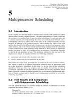
A connection is defined by means of a host source, a path composed of one or
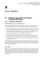
multiple switches and a host destination. For example, Figure 7.1 shows a connection
between hosts 1 and 100 on a path composed of switches A, C, E and F.
Another important aspect in networks is the routing. Routing is a mechanism by
which a network device (usually a router or a switch) collects, maintains and dissem-
inates information about paths (or routes) to various destinations on a network. There
exist multiple routing algorithms that enable determination of the best, or shortest,
7.2 NETWORK AND TRAFFIC MODELS 131
Packet-switching network
Host
1
Host
10
Host
100
Host
50
Switch
A
Switch
B
Switch
D
Switch
E
Switch
C
Switch
F
Host
2
Figure 7.1 General architecture of a packet-switching network
path to a particular destination. In connectionless networks, such as IP, routing is
generally dynamic (i.e. the path is selected for each packet considered individually)
and in connection-oriented networks, such as ATM, routing is generally fixed (i.e. all
the packets on the same connection follow the same path, except in the event of failure
of a switch or a link). In the remainder of this chapter, we assume that prior to the
establishment of a connection, a routing algorithm is run to determine a path from a
source to a destination, and that this algorithm is rerun whenever required to recompute
a new path, after a failure of a switch or a link on the current path. Thus, routing is
not developed further in this book.
The service disciplines presented in this chapter are based on an explicit reservation
of resources before any transfer of data, and the resource allocation is based on the
identification of source–destination pairs. In the literature, multiple terms (particularly
connections, virtual circuits, virtual channels and sessions) are used interchangeably to
identify source–destination pairs. In this chapter we use the term ‘connection’. Thus,
the disciplines we will study are called connection-oriented disciplines.
7.2.2 Packet-switching network issues
Input and output links
A packet-switching network is any communication network that accepts and delivers
individual packets of information. Most modern networks are packet-switching. As
shown in Figure 7.1, a packet-switching network is composed of a set of nodes (called
switches in networks like ATM, or routers in Internet environments) to which a set of
hosts (or user end-systems) is connected. In the following, we use the term ‘switch’ to
designate packet-switching nodes; thus, the terms ‘switch’ and ‘router’ are interchange-
able in the context of this chapter. Hosts, which represent the sources of data, submit
packets to the network to deliver them to their destination. The packets are routed
hop-by-hop, across switches, before reaching their destinations (host destinations).
132 7 PACKET SCHEDULING IN NETWORKS
Intput
links
Input queues
Packet switch
Output queues
Output
links
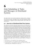
Figure 7.2 Simplified architecture of a packet switch
A simple packet switch has input and output links (see Figure 7.2). Each link has a
fixed rate (not all the links need to have the same rate). Packets arrive on input links
and are assigned an output link by some routing/switching mechanism. Each output
link has a queue (or multiple queues). Packets are removed from the queue(s) and
sent on the appropriate output link at the rate of the link. Links between switches and
between switches and hosts are assumed to have bounded delays. By link delay we
mean the time a packet takes to go from one switch (or from the source host) to the
next switch (or to the destination host). When the switches are connected directly, the
link delay depends mainly on the propagation delay. However, in an interconnecting
environment, two switches may be interconnected via a local area network (such as a
token bus or Ethernet); in this case, the link delay is more difficult to bound.
A plethora of proposals for identifying suitable architectures for high-speed switches
has appeared in the literature. The design proposals are based on various queuing
strategies, mainly output queuing and input queuing. In output queuing, when a packet
arrives at a switch, it is immediately put in the queue associated with the corresponding
output link. In input queuing, each input link maintains a first-come-first-served (FCFS)
queue of packets and only the first packet in the queue is eligible for transmission
during a given time slot. Such a strategy, which is simple to implement, suffers from
a performance bottleneck, namely head-of-line blocking (i.e. when the packet at the
head of the queue is blocked, all the packets behind it in the queue are prevented from
being transmitted, even when the output link they need is idle). Few works have dealt
with input queuing strategies, and the packet scheduling algorithms that are most well
known and most commonly used in practice, by operational switches, are based on
output queuing. This is the reason why, in this book, we are interested only in the
algorithms that belong to the output queuing category.
In general, a switch can have more than one output link. When this is the case,
the various output links are managed independently of each other. To simplify the
notations, we assume, without loss of generality, that there is one output link per
switch, so we do not use specific notations to distinguish the output links.
7.2 NETWORK AND TRAFFIC MODELS 133
End-to-end delay of packet in a switched network
The end-to-end delay of each packet through a switched network is the sum of the
delays it experiences passing through all the switches en route. More precisely, to deter-
mine the end-to-end delay a packet experiences in the network, four delay components
must be considered for each switch:
• Queuing delay is the time spent by the packet in the server queue while waiting
for transmission. Note that this delay is the most difficult to bound.
• Transmission delay is the time interval between the beginning of transmission of
the first bit and the end of transmission of the last bit of the packet on the output
link. This time depends on the packet length and the rate of the output link.
• Propagation delay is the time required for a bit to go from the sending switch
to the receiving switch (or host). This time depends on the distance between the
sending switch and the next switch (or the destination host). It is also independent
of the scheduling discipline.
• Processing delay is any packet delay resulting from processing overhead that is
not concurrent with an interval of time when the server is transmitting packets.
On one hand, some service disciplines consider the propagation delay and others do
not. On the other hand, some authors ignore the propagation delay and others do
not, when they analyse the performances of disciplines. Therefore, we shall slightly
modify certain original algorithms and results of performance analysis to consider the
propagation delay, which makes it easier to compare algorithm performances. Any
modification of the original algorithms or performance analysis results is pointed out
in the text.
High-speed networks requirements
High-speed networks call for simplicity of traffic management algorithms in terms of
the processing cost required for packet management (determining deadlines or finish
times, insertion in queues, etc.), because a significant number (several thousands) of
packets can traverse a switch in a short time interval, while requiring very short times
of traversing. In order not to slow down the functioning of a high-speed network,
the processing required for any control function should be kept to a minimum. In
consequence, packet scheduling algorithms should have a low overhead. It is worth
noting that almost all switches on the market are based on hardware implementation
of some packet management functions.
7.2.3 Traffic models and quality of service
Traffic models
The efficiency and the capabilities of QoS guarantees provided by packet scheduling
algorithms are widely influenced by the characteristics of the data flows transmitted
134 7 PACKET SCHEDULING IN NETWORKS
by sources. In general, it is difficult (even impossible) to determine a bound on packet
delay and jitter if there is no constraint on packet arrival patterns when the bandwidth
allocated to connections is finite. As a consequence, the source should specify the
characteristics of its traffic.
A wide range of traffic specifications has been proposed in the literature. However,
most techniques for guaranteeing QoS have investigated only specific combinations
of traffic specifications and scheduling algorithms. The models commonly used for
characterizing real-time traffic are: the periodic model, the (Xmin, Xave, I ) model, the
(σ, ρ) model and the leaky bucket model.
• Periodic model. Periodic traffic travelling on a connection c is generated by a
periodic task and may be specified by a couple (Lmax
c
,T
c
)whereLmax
c
is the
maximum length of packets, and T
c
is the minimum length of the interval between
the arrivals of any two consecutive packets (it is simply called the period ).
• (Xmin, Xave, I ) model. Three parameters are used to characterize the traffic: Xmin
is the minimum packet inter-arrival time, Xave is the average packet inter-arrival
time, and I is the time interval over which Xave is computed. The parameters Xave
and I are used to characterize bursty traffic.
• (σ, ρ) model (Cruz, 1991a, b). This model describes traffic in terms of a rate
parameter ρ and a burst parameter σ such that the total number of packets from a
connection in any time interval is no more than σ + ρt.
• Leaky bucket model. Various definitions and interpretations of the leaky bucket
have been proposed. Here we give the definition of Turner, who was the first
to introduce the concept of the leaky bucket (1986): a counter associated with
each user transmitting on a connection is incremented whenever the user sends
packets and is decremented periodically. If the counter exceeds a threshold, the
network discards the packets. The user specifies a rate at which the counter is
decremented (this determines the average rate) and a value of the threshold (a
measure of burstiness). Thus, a leaky bucket is characterized by two parameters,
rate ρ and depth σ. It is worth noting that the (σ, ρ) model and the leaky bucket
model are similar.
Quality of service requirements
Quality of service (QoS) is a term commonly used to mean a collection of parameters
such as reliability, loss rate, security, timeliness, and fault tolerance. In this book,
we are only concerned with timeliness QoS parameters (i.e. transfer delay of packets
and jitter).
Several different ways of categorizing QoS may be identified. One commonly used
categorization is the distinction between deterministic and statistical guarantees. In
the deterministic case, guarantees provide a bound on performance parameters (for
example a bound on transfer delay of packets on a connection). Statistical guarantees
promise that no more than a specified fraction of packets will see performance below a
certain specified value (for example, no more than 5% of the packets would experience
transfer delay greater than 10 ms). When there is no assurance that the QoS will in
7.2 NETWORK AND TRAFFIC MODELS 135
fact be provided, the service is called best effort service. The Internet today is a good
example of best effort service. In this book we are only concerned with deterministic
approaches for QoS guarantee.
For distributed real-time applications in which messages arriving later than their
deadlines lose their value either partially or completely, delay bounds must be guaran-
teed. For communications such as distributed control messages, which require absolute
delay bounds, the guarantee must be deterministic. In addition to delay bounds, delay
jitter (or delay variation) is also an important factor for applications that require smooth
delivery (e.g. video conferencing or telephone services). Smooth delivery can be pro-
vided either by rate control at the switch level or buffering at the destination.
Some applications, such as teleconferencing, are not seriously affected by delay
experienced by packets in each video stream, but jitter and throughput are important
for these applications. A packet that arrives too early to be processed by the destination
is buffered. Hence, a larger jitter of a stream means that more buffers must be provided.
For this reason, many packet scheduling algorithms are designed to keep jitter small.
From the point of view of a client requiring bounded jitter, the ideal network would
look like a link with a constant delay, where all the packets passed to the network
experience the same end-to-end transfer delay.
Note that in the communication literature, the term ‘transfer delay’ (or simply
‘delay’) is used instead of the term ‘response time’, which is currently used in the
task scheduling literature.
Quality of service management functions
Numerous functions are used inside networks to manage the QoS provided in order to
meet the needs of users and applications. These functions include:
• QoS establishment: during the (connection) establishment phase it is necessary for
the parties concerned to agree upon the QoS requirements that are to be met in the
subsequent systems activity. This function may be based on QoS negotiation and
renegotiation procedures.
• Admission control : this is the process of deciding whether or not a new flow (or
connection) should be admitted into the network. This process is essential for QoS
control, since it regulates the amount of incoming traffic into the network.
• QoS signalling protocols: they are used by end-systems to signal to the network
the desired QoS. A corresponding protocol example is the Resource ReSerVation
Protocol (RSVP).
• Resource management: in order to achieve the desired system performance, QoS
mechanisms have to guarantee the availability of the shared resources (such as
buffers, circuits, channel capacity and so on) needed to perform the services
requested by users. Resource reservation provides the predictable system behaviour
necessary for applications with QoS constraints.
• QoS maintenance: its goal is to maintain the agreed/contracted QoS; it includes
QoS monitoring (the use of QoS measures to estimate the values of a set of QoS
parameters actually achieved) and QoS control (the use of QoS mechanisms to
136 7 PACKET SCHEDULING IN NETWORKS
modify conditions so that a desired set of QoS characteristics is attained for some
systems activity, while that activity is in progress).
• QoS degradation and alert: this issues a QoS indication to the user when the lower
layers fail to maintain the QoS of the flow and nothing further can be done by QoS
maintenance mechanisms.
• Traffic control : this includes traffic shaping/conditioning (to ensure that traffic enter-
ing the network adheres to the profile specified by the end-user), traffic scheduling
(to manage the resources at the switch in a reasonable way to achieve particular
QoS), congestion control (for QoS-aware networks to operate in a stable and effi-
cient fashion, it is essential that they have viable and robust congestion control
capabilities), and flow synchronization (to control the event ordering and precise
timings of multimedia interactions).
• Routing: this is in charge of determining the ‘optimal’ path for packets.
In this book devoted to scheduling, we are only interested in the function related to
packet scheduling.
7.3 Service Disciplines
There are two distinct phases in handling real-time communication: connection estab-
lishment and packet scheduling. The combination of a connection admission control
(CAC) and a packet scheduling algorithm is called a service discipline. While CAC
algorithms control acceptation, during connection establishment, of new connections
and reserve resources (bandwidth and buffer space) to accepted connections, packet
scheduling algorithms allocate, during data transfer, resources according to the reserva-
tion. As previously mentioned, when the connection admission control function is not
significant for the discussion, the terms ‘service discipline’ and ‘scheduling algorithm’
are interchangeable.
7.3.1 Connection admission control
The connection establishment selects a path (route) from the source to the destination
along which the timing constraints can be guaranteed. During connection establishment,
the client specifies its traffic characteristics (i.e. minimum inter-arrival of packets,
maximum packet length, etc.) and desired performance requirements (delay bound,
delay jitter bound, and so on). The network then translates these parameters into local
parameters, and performs a set of connection admission control tests at all the switches
along the path of each accepted connection. A new connection is accepted only if
there are enough resources (bandwidth and buffer space) to guarantee its performance
requirements at all the switches on the connection path. The network may reject a
connection request due to lacks of resources or administrative constraints.
Note that a switch can provide local guarantees to a connection only when the traffic
on this connection behaves according to its specified traffic characteristics. However,
7.3 SERVICE DISCIPLINES 137
load fluctuations at previous switches may distort the traffic pattern of a connection and
cause an instantaneous higher rate at some switch even when the connection satisfied
the specified rate constraint at the entrance of the network.
7.3.2 Taxonomy of service disciplines
In the past decade, a number of service disciplines that aimed to provide perfor-
mance guarantees have been proposed. These disciplines may be classified according
to various criteria. The main classifications used to understand the differences between
disciplines are the following:
• Work-conserving versus non-work-conserving disciplines. Work-conserving algo-
rithms schedule a packet whenever a packet is present in the switch. Non-work-
conserving algorithms reduce buffer requirements in the network by keeping the
link idle even when a packet is waiting to be served. Whereas non-work-conserving
disciplines can waste network bandwidth, they simplify network resource control
by strictly limiting the output traffic at each switch.
• Rate-allocating versus rate-controlled disciplines. Rate-allocating disciplines allow
packets on each connection to be transmitted at higher rates than the minimum
guaranteed rate, provided the switch can still meet guarantees for all connections.
In a rate-controlled discipline, a rate is guaranteed for each connection, but the
packets from a connection are never allowed to be sent above the guaranteed rate.
• Priority-based versus frame-based disciplines. In priority-based schemes, packets
have priorities assigned according to the reserved bandwidth or the required delay
bound for the connection. The packet transmission (service) is priority driven. This
approach provides lower delay bounds and more flexibility, but basically requires
more complicated control logic at the switch. Frame-based schemes use fixed-size
frames, each of which is divided into multiple packet slots. By reserving a certain
number of packet slots per frame, connections are guaranteed with bandwidth and
delay bounds. While these approaches permit simpler control at the switch level,
they can sometimes provide only limited controllability (in particular, the number
of sources is fixed and cannot be adapted dynamically).
• Rate-based versus scheduler-based disciplines. A rate-based discipline is one that
provides a connection with a minimum service rate independent of the traffic char-
acteristics of other connections (though it may serve a connection at a rate higher
than this minimum). The QoS requested by a connection is translated into a trans-
mission rate or bandwidth. There are predefined allowable rates, which are assigned
static priorities. The allocated bandwidth guarantees an upper delay bound for
packets. The scheduler-based disciplines instead analyse the potential interactions
between packets of different connections, and determine if there is any possibility
of a deadline being missed. Priorities are assigned dynamically based on deadlines.
Rate-based methods are simpler to implement than scheduler-based ones. Note
that scheduler-based methods allow bandwidth, delay and jitter to be allocated
independently.
138 7 PACKET SCHEDULING IN NETWORKS
7.3.3 Analogies and differences with task scheduling
In the next sections, we describe several well-known service disciplines for real-time
packet scheduling. These disciplines strongly resemble the ones used for task schedul-
ing seen in previous chapters. Compared to scheduling of tasks, the transmission link
plays the same role as the processor as a central resource, while the packets are the
units of work requiring this resource, just as tasks require the use of a processor. With
this analogy, task scheduling methods may be applicable to the scheduling of packets
on a link. The scheduler allocates the link according to some predefined discipline.
Many of the packet scheduling algorithms assign a priority to a packet on its arrival
and then schedule the packets in the priority order. In these scheduling algorithms,
a packet with higher priority may arrive after a packet with lower priority has been
scheduled. On one hand, in non-preemptive scheduling algorithms, the transmission
of a lower priority is not preempted even after a higher priority packet arrives. Con-
sequently, such algorithms elect the highest priority packet known at the time of the
transmission completion of every packet. On the other hand, preemptive scheduling
algorithms always ensure that the packet in service (i.e. the packet being transmitted)
is the packet with the highest priority by possibly preempting the transmission of a
packet with lower priority.
Preemptive scheduling, as used in task scheduling, cannot be used in the context
of message scheduling, because if the transmission of a message is interrupted, the
message is lost and has to be retransmitted. To achieve the preemptive scheduling,
the message has to be split into fragments (called packets or cells) so that message
transmission can be interrupted at the end of a fragment transmission without loss (this
is analogous to allowing an interrupt of a task at the end of an instruction execution).
Therefore, a message is considered as a set of packets, where the packet size is bounded.
Packet transmission is non-preemptive, but message transmission can be considered to
be preemptive. As we shall see in this chapter, packet scheduling algorithms are non-
preemptive and the packet size bound has some effects on the performance of the
scheduling algorithms.
7.3.4 Properties of packet scheduling algorithms
A packet scheduling algorithm should possess several desirable features to be useful
for high-speed switching networks:
• Isolation (or protection) of flows: the algorithm must isolate a connection from
undesirable effects of other (possibly misbehaving) connections.
• Low end-to-end delays: real-time applications require from the network low
end-to-end delay guarantees.
• Utilization (or efficiency): the scheduling algorithm must utilize the output link
bandwidth efficiently by accepting a high number of connections.
• Fairness: the available bandwidth of the output link must be shared among con-
nections sharing the link in a fair manner.
7.4 WORK-CONSERVING SERVICE DISCIPLINES 139
• Low overhead: the scheduling algorithm must have a low overhead to be
used online.
• Scalability (or flexibility): the scheduling algorithm must perform well in switches
with a large number of connections, as well as over a wide range of output
link speeds.
7.4 Work-Conserving Service Disciplines
In this section, we present the most representative and most commonly used work-
conserving service disciplines, namely the weighted fair queuing, virtual clock, and
delay earliest-due-date disciplines. These disciplines have different delay and fairness
properties as well as implementation complexity. The priority index, used by the sched-
uler to serve packets, is called ‘auxiliary virtual clock’ for virtual clock, ‘virtual finish
time’ for weighted fair queuing, and ‘expected deadline’ for delay earliest-due-date.
The computation of priority index is based on just the rate parameter or on both the
rate and delay parameters; it may be dependent on the system load.
7.4.1 Weighted fair queuing discipline
Fair queuing discipline
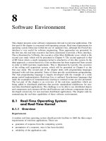
Nagle (1987) proposed a scheduling algorithm, called fair queuing, based on the use of
separate queues for packets from each individual connection (Figure 7.3). The objective
.
.
.
...
Intput
links
...
Output link 1
Queue for connection n
Queue for connection 1
Packet switch
Round
robin
server
Output link x
Queue for connection m
Queue for connection k
Switching
Round
robin
server
Figure 7.3 General architecture of fair queuing based server
140 7 PACKET SCHEDULING IN NETWORKS
of this algorithm is to protect the network from hosts that are misbehaving: in the pres-
ence of well-behaved and misbehaving hosts, this strategy ensures that well-behaved
hosts are not affected by misbehaving hosts. With fair queuing discipline, connections
share equally the output link of the switch. The multiple queues of a switch, associated
with the same output link, are served in a round-robin fashion, taking one packet from
each nonempty queue in turn; empty queues are skipped over and lose their turn.
Weighted fair queuing discipline
Demers et al. (1989) proposed a modification of Nagle’s fair queuing discipline to take
into account some aspects ignored in Nagle’s discipline, mainly the lengths of packets
(i.e. a source sending long packets should get more bandwidth than one sending short
packets), delay of packets, and importance of flows. This scheme is known as the
weighted fair queuing (WFQ) discipline even though it was simply called fair queuing
by its authors (Demers et al.) in the original paper. The same discipline has also been
proposed by Parekh and Gallager (1993) under the name packet-by-packet generalized
processor sharing system (PGPS). WFQ and PGPS are interchangeable.
To define the WFQ discipline, Demers et al. introduced a hypothetical service dis-
cipline where the transmission occurs in a bit-by-bit round-robin (BR) fashion. Indeed,
‘ideal fairness’ would have as a consequence that each connection transmits a bit in
each turn of the round-robin service. The bit-by-bit round-robin algorithm is also called
Processor Sharing (PS) service discipline.
Bit-by-bit round-robin discipline (or processor sharing discipline)LetR
s
(t) denote
the number of rounds made in the Round-Robin discipline up to time t at a switch s; R
s
(t)
is a continuous function, with the fractional part indicating partially completed rounds.
R
s
(t) is also called virtual system time.LetNac
s
(t) be the number of active connections
at switch s (a connection is active if it has bits waiting in its queue at time t). Then:
dR
s
dt
=
r
s
Nac
s
(t)
where r
s
is the bit rate of the output link of switch s.
A packet of length L whose first bit gets serviced at time t
0
will have its last bit
serviced L rounds later, at time t such that R
s
(t) = R
s
(t
0
) + L.LetAT
c,p
s
be the time
that packet p on connection c arrives at the switch s, and define the numbers S
c,p
s
and F
c,p
s
as the values of R
s
(t) when the packet p starts service and finishes service.
F
c,p
s
is called the finish number of packet p. The finish number associated with a
packet, at time t, represents the time at which this packet would complete service in
the corresponding BR service if no additional packets were to arrive after time t. L
c,p
denotes the size of the packet p. Then,
S
c,p
s
= max{F
c,p−1
s
,R
s
(AT
c,p
s
)} for p>1 (7.1)
F
c,p
s
= S
c,p
s
+ L
c,p
for p ≥ 1 (7.2)
Equation (7.1) means that the pth packet from connection c starts service when it
arrives if the queue associated with c is empty on packet p’s arrival, or when packet
p − 1 finishes otherwise. Packets are numbered 1, 2,... and S
c,1
s
= AT
c,1
s
(for all
connections). Only one packet per queue can start service.
7.4 WORK-CONSERVING SERVICE DISCIPLINES 141
Weighted bit-by-bit round-robin discipline To take into account the requirements
(mainly in terms of bandwidth) and the importance of each connection, a weight φ
c
s
is assigned to each connection c in each switch s. This number represents how many
queue slots that the connection gets in the bit-by-bit round-robin discipline. In other
words, it represents the fraction of output link bandwidth allocated to connection c.
The new relationships for determining R
s
(t) and F
c,p
s
are:
Nac
s
(t) =
x∈CnAct
s
(t)
φ
x
s
(7.3)
F
c,p
s
= S
c,p
s
+
L
c,p
φ
c
s
for p ≥ 1 (7.4)
where CnAct
s
(t) is the set of active connections at switch s at time t. Note that the
combination of weights and BR discipline is called weighted bit-by-bit round-robin
(WBR), and is also called the generalized processor sharing (GPS) discipline, which
is the term most often used in the literature.
Practical implementation of WBR (or GPS) discipline The GPS discipline is an ide-
alized definition of fairness as it assumes that packets can be served in infinitesimally
divisible units. In other words, GPS is based on a fluid model where the packets
are assumed to be indefinitely divisible and multiple connections may transmit traffic
through the output link simultaneously at different rates. Thus, sending packets in a
bit-by-bit round-robin fashion is unrealistic (i.e. impractical), and the WFQ scheduling
algorithm can be thought of as a way to emulate the hypothetical GPS discipline by
a practical packet-by-packet transmission scheme. With the packet-by-packet round-
robin scheme, a connection c is active whenever condition (7.5) holds (i.e. whenever
the round number is less than the largest finish number of all packets queued for
connection c).
R
s
(t) ≤ F
c,p
s
for p = max{j |AT
c,j
s
≤ t} (7.5)
The quantities F
c,p
s
, computed according to equality (7.4), define the sending order
of the packets. Whenever a packet finishes transmission, the next packet transmitted
(serviced) is the one with the smallest F
c,p
s
value. In Parekh and Gallager (1993), it is
shown that over sufficiently long connections, this packetized algorithm asymptotically
approaches the fair bandwidth allocation of the GPS scheme.
Round-number computation The round number R
s
(t) is defined to be the number
of rounds that a GPS server would have completed at time t. To compute the round
number, the WFQ server keeps track of the number of active connections, Nac
s
(t),
defined according to equality (7.3), since the round number grows at a rate that is
inversely proportional to Nac
s
(t). However, this computation is complicated by the
fact that determining whether or not a connection is active is itself a function of
the round number. Many algorithms have been proposed to ease the computation of
R
s
(t). The interested reader can refer to solutions suggested by Greenberg and Madras
(1992), Keshav (1991) and Liu (2000). Note that R
s
(t), as previously defined, cannot
be computed whenever there is no connection active (i.e. if Nac
s
(t) = 0). This problem
may be simply solved by setting R
s
(t) to 0 at the beginning of the busy period of each
142 7 PACKET SCHEDULING IN NETWORKS
switch (i.e. when the switch begins servicing packets), and by computing R
s
(t) only
during busy periods of the switch.
Example 7.1: Computation of the round number Consider two connections, 1 and
2, sharing the same output link of a switch s using a WFQ discipline. Suppose that
the speed of the output link is 1. Each connection utilizes 50% of the output link
bandwidth (i.e. φ
1
s
= φ
2
s
= 0.5). At time t = 0, a packet P
1,1
of size 100 bits arrives
on connection 1 and a packet P
2,1
of size 150 bits arrives on connection 2 at time
t = 50. Let us compute the values of R
s
(t) at times 50 and 100.
At time t = 0, packet P
1,1
arrives, and it is assigned a finish number F
1,1
s
= 200.
Packet P
1,1
starts immediately service. During the interval [0, 50], only connection
1 is active, thus N
ac
(t) = 0.5anddR(t)/dt = 1/0.5. In consequence, R(50) = 100.
At time t = 50, packet P
2,1
arrives, and it is assigned a finish number F
2,1
s
= 100 +
150/0.5 = 400. At time t = 100, packet P
1,1
completes service. In the interval [50,
100], N
ac
(t) = 0.5 + 0.5 = 1. Then, R(100) = R(50) + 50 = 150.
Bandwidth and end-to-end delay bounds provided by WFQ Parekh and Gallager
(1993) proved that each connection c is guaranteed a rate r
c
s
, at each switch s,defined
by equation (7.6):
r
c
s
=
φ
c
s
j∈C
s
φ
j
s
r
s
(7.6)
where C
s
is the set of connections serviced by switch s,andr
s
is the rate of the output
link of the switch. Thus, with a GPS scheme, a connection c can be guaranteed a
minimum throughput independent of the demands of the other connections. Another
consequence, is that the delay of a packet arriving on connection c can be bounded as
a function of the connection c queue length independent of the queues associated with
the other connections. By varying the weight values, one can treat the connections in a
variety of different ways. When a connection c operates under leaky bucket constraint,
Parekh and Gallager (1994) proved that the maximum end-to-end delay of a packet
along this connection is bounded by the following value:
σ
c
+ (K
c
− 1)L
c
ρ
c
+
K
c
s=1
Lmax
s
r
s
+ π (7.7)
where σ
c
and ρ
c
are the maximum buffer size and the rate of the leaky bucket modelling
the traffic of connection c, K
c
is the total number of switches in the path taken
by connection c, L
c
is the maximum packet size from connection c, Lmax
s
is the
maximum packet size of the connections served by switch s, r
s
is the rate of the
output link associated with server s in c’s path, and π is the propagation delay from
the source to destination. (π is considered negligible in Parekh and Gallager (1994).)
Note that the WFQ discipline does not integrate any mechanism to control jitter.
Hierarchical generalized processor sharing
The hierarchical generalized processor sharing (H-GPS) system provides a general flex-
ible framework to support hierarchical link sharing and traffic management for different
7.4 WORK-CONSERVING SERVICE DISCIPLINES 143
service classes (for example, three classes of service may be considered: hard real-time,
soft real-time and best effort). H-GPS can be viewed as a hierarchical integration of
one-level GPS servers. With one-level GPS, there are multiple packet queues, each
associated with a service share. During any interval when there are backlogged con-
nections, the server services all backlogged connections simultaneously in proportion
to their corresponding service shares. With H-GPS, the queue at each internal node
is a logical one, and the service that this queue receives is distributed instantaneously
to its child nodes in proportion to their relative service shares until the H-GPS server
reaches the leaf nodes where there are physical queues (Bennett and Zhang, 1996b).
Figure 7.4 gives an example of an H-GPS system with two levels.
Other fair queuing disciplines
Although the WFQ discipline offers advantages in delay bounds and fairness, its
implementation is complex because of the cost of updating the finish numbers. Its
computation complexity is asymptotically linear in the number of connections serviced
by the switch. To overcome this drawback, various disciplines have been proposed to
approximate the GPS with a lower complexity: worst-case fair weighted fair queu-
ing (Bennett and Zhang, 1996a), frame-based fair queuing (Stiliadis and Varma, 1996),
start-time fair queuing (Goyal et al., 1996), self-clocked fair queuing (Golestani, 1994),
and deficit round-robin (Shreedhar and Varghese, 1995).
7.4.2 Virtual clock discipline
The virtual Clock discipline, proposed by Zhang (1990), aims to emulate time divi-
sion multiplexing (TDM) in the same way as fair queuing emulates the bit-by-bit
round-robin discipline. TDM is a type of multiplexing that combines data streams by
assigning each connection a different time slot in a set. TDM repeatedly transmits a
.
.
.
GPS
GPS
Output link
...
...
Input links
GPS
Figure 7.4 Hierarchical GPS server with two levels
144 7 PACKET SCHEDULING IN NETWORKS
fixed sequence of time slots over the medium. A TDM server guarantees each user
a prescribed transmission rate. It also eliminates interference among users, as if there
were firewalls protecting individually reserved bandwidth. However, users are limited
to transmission at a constant bit rate. Each user is allocated a slot to transmit. Capac-
ities are wasted when a slot is reserved for a user that has no data to transmit at
that moment. The number of users in a TDM server is fixed rather than dynamically
adjustable.
The goal of the virtual clock (VC) discipline is to achieve both the guaranteed
throughput for users and the firewall of a TDM server, while at the same time preserving
the statistical multiplexing advantages of packet switching.
Each connection c reserves its average required bandwidth r
c
at connection estab-
lishment time. The reserved rates for connections, at switch s, are constrained by:
x∈C
s
r
x
≤ r
s
(7.8)
where C
s
is the set of connections multiplexed at server s (i.e. the set of connections
that traverse the switch s)andr
s
is the rate of switch s for the output link shared by
the multiplexed connections. Each connection c also specifies an average time interval,
A
c
. That is, over each A
c
time period, dividing the total amount of data transmitted by
A
c
should result in r
c
. This means that a connection may vary its transmission rate,
but with respect to specified parameters r
c
and A
c
.
Packet scheduling
Each switch s along the path of a connection c uses two variables VC
c
s
(virtual clock)
and auxVC
c
s
(auxiliary virtual clock) to control and monitor the flow of connection c.
The virtual clock VC
c
s
is advanced according to the specified average bit rate (r
c
)of
connection c; the difference between this virtual clock and the real-time indicates how
closely a running connection is following its specified bit rate. The auxiliary virtual
clock auxVC
c
s
is used to compute virtual deadlines of packets. VC
c
s
and auxVC
c
s
will
contain the same value most of the time — as long as packets from a connection arrive
at the expected time or earlier. auxVC
c
s
may have a larger value temporarily, when a
burst of packets arrives very late in an average interval, until being synchronized with
VC
c
s
again.
Upon receiving the first packet on a connection c, those two virtual clocks are set
to the arrival (real) time of this packet. When a packet p, whose length is L
c,p
bits,
arrives, at time AT
c,p
s
, on connection c, at the switch s, the virtual clocks are updated
as follows:
auxV C
c
s
←−−− max{AT
c,p
s
,auxVC
c
s
}+L
c,p
/r
c
(7.9)
VC
c
s
←−−− VC
c
s
+ L
c,p
/r
c
(7.10)
Then, the packet p is stamped with the auxVC
c
s
value and inserted in the output link
queue of the switch s. Packets are queued and served in order of increasing stamp
7.4 WORK-CONSERVING SERVICE DISCIPLINES 145
auxVC values (ties are ordered arbitrarily). The auxVC value associated with a packet
is also called finish time (or virtual transmission deadline).
Flow monitoring
Since connections specify statistical parameters (r
c
and A
c
), a mechanism must be
used to control the data submitted by these connections according to their reservations.
Upon receiving each set of A
c
· r
c
bits (or the equivalent of this bit-length expressed in
packets) from connection c, the switch s checks the connection in the following way:
• If VC
c
s
− ‘Current Real-time’ > Threshold, a warning message is sent to the source
of connection c. Depending on how the source reacts, further control actions may
be necessary (depending on resource availability, connection c may be punished
by longer queuing delay, or even packet discard).
• If VC
c
s
< ‘Current Real-time’, VC
c
s
is assigned ‘Current Real-time’.
The auxVC
c
s
variable is needed to take the arrival time of packets into account. When a
burst of packets arrives very late in an average interval, although the VC
c
s
value may be
behind real-time at that moment, the use of auxVC
c
s
will ensure the first packet to bear a
stamp value with an increment of L
c,p
/r
c
to the previous one. These stamp values will
then cause this burst of packets to be interleaved, in the waiting queue, with packets that
have arrived from other connections, if there are any. If a connection transmits at a rate
lower than its specified rate, the difference between the virtual clock VC and real-time
may be considered as a ‘credit’ that the connection has built up. By replacing VC
c
s
by
auxVC
c
s
in the packet stamping, a connection can no longer increase the priority of its
packets by saving credits, even within an average interval. VC
c
s
retains its role as a con-
nection meter that measures the progress of a statistical packet flow; its value may fall
behind the real-time clock between checking (or monitoring) points in order to tolerate
packet burstiness within each average interval. If a connection were allowed to save up
an arbitrary amount of credit, it could remain idle during most of the time and then send
all its data in burst; such behaviour may cause temporary congestion in the network.
In cases where some connections violate their reservation (i.e. they transmit at a rate
higher than that agreed during connection establishment) well-behaved connections will
not be affected, while the offending connections will receive the worst service (because
their virtual clocks advance too far beyond real-time, their packets will be placed at
the end of the service queue or even discarded).
Some properties of the virtual clock discipline
Figueira and Pasquale (1995) proved that the upper bound of the packet delay for the
VC discipline is the same as that obtained for the WFQ discipline (see (7.7)) when the
connections are leaky bucket constrained.
Note that the VC algorithm is more efficient than the WFQ one, as it has a lower
overhead: computing virtual clocks is simpler than computing finish times as required
by WFQ.
146 7 PACKET SCHEDULING IN NETWORKS
7.4.3 Delay earliest-due-date discipline
A well-known dynamic priority-based service discipline is delay earliest-due-date (also
called delay EDD), introduced by Ferrari and Verma (1990), and refined by Kand-
lur et al. (1991). The delay EDD discipline is based on the classic EDF scheduling
algorithm presented in Chapter 2.
Connection establishment procedure
In order to provide real-time service, each user must declare its traffic characteristics
and performance requirements at the time of establishment of each connection c by
means of three parameters: Xmin
c
(the minimum packet inter-arrival time), Lmax
c
(the maximum length of packets), and D
c
(the end-to-end delay bound). To establish
a connection, a client sends a connection request message containing the previous
parameters. Each switch along the connection path performs a test to accept (or reject)
the new connection. The test consists of verifying that enough bandwidth is available,
under worst case, in the switch to accommodate the additional connection without
impairing the guarantees given to the other accepted connections. Thus, inequality
(7.11) should be satisfied:
x∈C
s
ST
x
s
/Xmin
x
< 1 (7.11)
where ST
x
s
is the maximum service time in the switch s for any packet from connection
c. It is the maximum time to transmit a packet from connection c and mainly depends on
the speed of the output link of switch s and the maximum packet size on connection c,
Lmax
c
. C
s
is the set of the connections traversing the switch s including the connection
c to be established.
If inequality (7.11) is satisfied, the switch s determines the local delay OD
c
s
that
it can offer (and guarantee) for connection c. Determining the local deadline value
depends on the utilization policy of resources at each switch. The delay EDD algorithm
may be used with multiple resource allocation strategies. For example, assignment of
local deadline may be based on Xmin
c
and D
c
. If the switch s accepts the connection
c, it adds its offered local delay to the connection request message and passes this
message to the next switch (or to the destination host) on the path. The destination
host is the last point where the acceptance/rejection decision of a connection can be
made. If all the switches on the path accept the connection, the destination host checks
if the sum of the local delays plus the end-to-end propagation delay π (in the original
version of delay EDD, π is considered negligible) is less than the end-to-end delay,
and then balances the end-to-end delay D
c
among all the traversed switches. Thus, the
destination host assigns to each switch s a local delay D
c
s
as follows:
D
c
s
=
D
c
− π −
N
j=1
OD
c
j
N
+ OD
c
s
(7.12)
where N is the number of switches traversed by the connection c. Note that the
local delay D
c
s
assignedtoswitchs by the destination host is never less than the local
delay OD
c
s
previously accepted by this switch. The destination host builds a connection