Tài liệu RADAR HORIZON / LINE OF SIGHT pdf
Bạn đang xem bản rút gọn của tài liệu. Xem và tải ngay bản đầy đủ của tài liệu tại đây (44.62 KB, 2 trang )
GROUND CLUTTER
WEATHER CLUTTER
INTERFERENCE
RADAR HORIZON
SHADOWING
h
FEET
R
NAUTICAL MILES
H
FEET
ANTENNA
HEIGHT
POINT "H"
H = 0.672(R-1.22 h)
2
5000
4000
3000
2000
10,000
1000
500
200
100
50
0
250
200
150
100
50
0
10,000
5000
4000
3000
2000
1000
0
500
200
100
50
25
25
250
200
150
100
50
0
h
H
SHADOW
R
R
NM
' 1.23 h
radar
with h in ft
R
NM
' 1.23 h
radar
% h
target
with h in ft
2-9.1
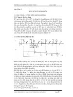
Figure 1. Radar Horizon and Shadowing
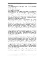
Figure 2. Earth Curvature Nomograph
RADAR HORIZON / LINE OF SIGHT
There are limits to the reach of radar
signals. At the frequencies normally used for
radar, radio waves usually travel in a straight
line. The waves may be obstructed by
weather or shadowing, and interference may
come from other aircraft or from reflections
from ground objects (Figure 1).
As also shown in Figure 1, an
aircraft may not be detected because it is
below the radar line which is tangent to the
earths surface.
Some rules of thumb are:
Range (to horizon):
Range (beyond horizon / over earth
curvature):
In obtaining the radar horizon equations, it is common practice to assume a value for the Earth's radius that is 4/3 times the
actual radius. This is done to
account for the effect of the
atmosphere on radar propagation.
For a true line of sight, such as used
for optical search and rescue, the
constant in the equations changes
from 1.23 to 1.06.
A nomograph for
determining maximum target range
is depicted in Figure 2. Although an
aircraft is shown to the left, it could
just as well be a ship, with radars on
a mast of height "h". Any target of
height (or altitude) "H" is depicted
on the right side.
See also Section 5-1 on
ducting and refraction, which may
increase range beyond these
distances.
5 10 15 20 25 30 35
150
450
400
350
300
250
200
10 k ft
20 k ft
30 k ft
40 k ft
TARGET ALTITUDE (k feet)
RADAR AIRCRAFT ALTITUDE
0
10 20 30 40 50 60 70 80 90 100
12
11
10
9
8
7
6
5
4
ANTENNA HEIGHT (feet)
R
NM
' 1.23 h
radar
% h
target
R
Visual
(NM) ' 1.05 Acft Alt in ft R
ESM
(NM) ' 1.5 Acft Alt in ft
R
max
(NM) ' 1.23 h
r
2-9.2
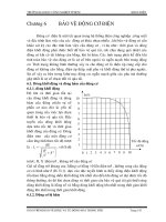
Figure 3. Aircraft Radar vs Aircraft Target Maximum Range
Figure 4. Ships Radar Horizon with Target on the Surface
This data was expanded
in Figure 3 to consider the
maximum range one aircraft can
detect another aircraft using:
(with h in feet)
It can be used for surface
targets if H = 0. It should be
target
noted that most aircraft radars are
limited in power output, and
would not detect small or surface
objects at the listed ranges.
Other general rules of thumb for surface "targets/radars" are:
For Visual SAR: For ESM:
Figure 4 depicts
the maximum range that a
ship height antenna can
detect a zero height object
(i.e. rowboat etc).
In this case "H" = 0, and
the general equation
becomes:
Where h is the height of
r
the radar in feet.