Tài liệu Clutches and brakes design and selection P4 pdf
Bạn đang xem bản rút gọn của tài liệu. Xem và tải ngay bản đầy đủ của tài liệu tại đây (554.06 KB, 16 trang )
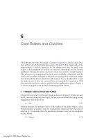
4
LinearlyActingExternalandInternal
DrumBrakes
Linearlyactingdrumbrakesarethosefittedwithshoeswhich,whenacti-
vated,approachthedrumbymovingparalleltoaradiusthroughthecen-
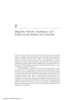
teroftheshoe.TypicallinearlyactingdrumbrakesareillustratedinFigures
1–3.
Analysisoflinearlyactingbrakesincludesthoseinwhichthecentrally
pivotedshoesareattachedtopivotedlevers,asinFigure1.Includingbrakes
ofthisdesignwithinthecategoryoflinearlyactingbrakesisjustifiedifthey
aredesignedsothattheappliedforcesontheshoesandliningsactalongthe
radiioftheshaftsthattheygripwhenthebrakesareapplied.Brakesofthis
typemayacteitheruponbrakedrumsordirectlyuponrotatingshaftsandare
suitableforuseinheavy-dutyapplications,suchasfoundinminingand
constructionequipmentandinmaterials-handlingmachinery.
Internallinearlyactingdrumbrakes,suchasusedontrucksinEurope,
maybedesignedasinFigure2.Eitherpneumaticorhydrauliccylindersor
cams may be used to force the shoes outwardly against the drum. The cylin-
ders or cams also serve as anchors to prevent rotation and react against the
vehicle frame. The springs shown are to retract the shoes when the brake
is released.
A collection of segmented brake pads (backing plate plus lining) along
the entire circumference of the drum may be arranged as in Figure 3 to move
outwardly against a drum, as in Figure 3a, or inwardly against a drum, as in
Figure3b.Thebrakepads,orshoes,arethemselvesconstrainedagainst
Copyright © 2004 Marcel Dekker, Inc.
rotationbyanchorpinsthatfitintoshortradialslotsbetweentheshoesand
areattachedtotherimofthecircularframe,asshowninFigure3a.Brake
actuationisaccomplishedbyusingairtoexpandthenormallyflatelasto-
meric-fabricannulartubeshowninthatfigurebetweenthebrakepadsandthe
circularframe.Whendesignedtomoveinwardlyagainstadrum,asinFigure
3b,thebrakeliningisrivetedtoadifferentlycontouredbackingplatewhich
hasshouldersateachendtoresistatwistingtorqueandwhichisfittedwitha
centralslotthatacceptstheanchorpintotheouterframeateachsideofthe
shoe.Thisradialslotallowsthepadtomoverapidlyinwardbutprevents
tangentialmotion.
F
IGURE
1Linearlyacting,centrallypivotedshoebrake.(CourtesyoftheHindon
Corp., Charleston, SC)
Chapter 468
Copyright © 2004 Marcel Dekker, Inc.
I.BRAKINGTORQUEANDMOMENTSFORCENTRALLY
PIVOTEDEXTERNALSHOES
Tocalculatethetorque,wemustfirstfindanexpressionfortheliningpres-
sure.GuidedbythegeometryshowninFigure4,weseethattheliningpres-
surewillbegivenby
p¼kDcosuð1-1Þ
intermsoftheliningdeformationDiftheshoeanddrumareassumedtobe
absolutelyrigid.Maximumpressureoccurswhenu
g
0,sothatp
max
=kD.
Thusequation(1-1)becomes
p¼p
max
cosuð1-2Þ
andtheincrementaltangentialfrictionforceisgivenby
dF¼Ap
max
cosurwduð1-3Þ
F
IGURE
2Linearlyacting,twin-shoe,internaldrumbrakewithpneumaticactiva-
tion (Girling Twinstop). (Reprinted with permission. n1977 Society of Automotive
Engineers, Inc.)
Linearly Acting External and Internal Drum Brakes 69
Copyright © 2004 Marcel Dekker, Inc.
sothebrakingtorquebecomes
T¼Ap
max
r
2
w
Z
u
2
u
1
cosudu¼Ap
max
r
2
wðsinu
2
Àsinu
1
Þð1-4Þ
IndesignsdifferentfromthoseshowninFigure1itmayprove
convenienttohavetheshoepivotedaboutapointataradialdistanceRon
theaxisofsymmetry,suchaspointAinFigure4.ThemomentM
p
duetothe
pressureontheliningiszeroaboutpointAbecauseofthesymmetryofthe
shoeaboutthispoint.NosuchsymmetryexistsforthefrictionmomentM
f
,
however,sofromtheincrementalmomentduetofriction
dM
f
¼ðAp
max
rwcosuduÞðRcosuÀrÞ
F
IGURE
3Rimbrakeswithpneumaticactivation(alsousedasrimclutches).
(Courtesy of Eaton Corp., Airflex Division, Cleveland, Ohio.)
Chapter 470
Copyright © 2004 Marcel Dekker, Inc.
it follows that
M
f
¼ Ap
max
rw
Z
u
2
u
1
R cos
2
u À r cos u
ÀÁ
du
¼ Ap
max
rw R
f
0
2
þ
1
4
ðsin 2u
2
À sin 2u
1
Þ
!&
ð1-5Þ
À rðsin u
2
À sin u
1
Þ
'
where f
0
= u
2
À u
1
. The expression in equation (1-5) may be simplified by
observing that the symmetry of the shoe about A requires that
À u
1
¼ u
2
¼
B
0
2
ð1-6Þ
where B
0
is the angle subtended by the lining. Substitution of these values into
equation (1-5) leads to
M
f
¼ Ap
max
rw
R
2
ðf
0
þ sin f
0
ÞÀ2r sin
f
0
2
!
ð1-5aÞ
F
IGURE
3 Continued.
Linearly Acting External and Internal Drum Brakes 71
Copyright © 2004 Marcel Dekker, Inc.
whichsuggeststhatmomentM
f
willvanishiftheshoeispivotedat
R¼r
4sinðf
0
=2Þ
f
0
þsinf
0
ð1-7Þ
UponplottingR/rweobtainFigure5,whereintheratioincreases
smoothlyfrom1.0atf
0
=0to1.273atf
0
=krad.=180j.Thisclearly
indicatesthatitisimpossibletofindapivotpointforwhichM
f
=0foran
internallinearlyactingshoe.Thisconclusionis,ofcourse,unaffectedbythe
F
IGURE
4Geometryusedfortheanalysisofalinearlyactingexternalshoe.
Chapter 472
Copyright © 2004 Marcel Dekker, Inc.