Tài liệu Clutches and brakes design and selection P6 ppt
Bạn đang xem bản rút gọn của tài liệu. Xem và tải ngay bản đầy đủ của tài liệu tại đây (513.55 KB, 18 trang )
6
ConeBrakesandClutches
Thesebrakeshavetheadvantageofgreatertorqueforasmalleraxialforce
thaneithertypeofdiskbrakediscussedinChapter5.Themagnitudeofthe
improvementislimited,however,bytheobservationthatforsmallcone
anglesadisengagementforcemayberequired,dependingonthefriction
coefficient,becausetheinnerandouterconesmaytendtowedgetogether.
Thisisbecauseonengagementtheinnerconeisradiallycompressedandthe
outerconeisradiallyenlargedasthebrakeisengaged.Forsmallconeangles
theinducedfrictionforcedominatesthenormalforce,whichtendstoexpel
theinnercone,sothatanexternalforceisrequiredforseparation.This
characteristic,however,maybeusefulinthoseapplicationswhereabrakeis
toremainengagedinthepresenceofdisengagementforces.
I.TORQUEANDACTIVATIONFORCE
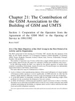
ThepertinentgeometryoftheconebrakeisshowninFigure1.Iftheinnerand
outer cones are concentric and rigid, the amount worn from the lining during
engagement will be given by
y ¼ kpr ð1-1Þ
where p denotes the pressure and r is the radius to the point where p acts.
Proportionality constant k may be evaluated by observing that the form of
relation (1-1) demands that the maximum pressure occur at the minimum
radius. Hence
y ¼ kp
max
r
i
ð1-2Þ
Copyright © 2004 Marcel Dekker, Inc.
Upon equating equations (1-1) and (1-2), we find that
p ¼ p
max
r
i
r
ð1-3Þ
Although the brake lining is more easily attached to the inner cone, with
the torque acting at the inner surface of the outer cone, we shall derive
formulas on the assumption that the torque acts on the outer surface of the
inner cone because this will give a torque capacity that the brake can equal or
exceed until the lining is destroyed. Thus
T ¼ A
Z
A
pr da ¼ Ap
max
r
i
Z
A
da ¼
2Akp
max
r
i
sin a
Z
r
o
r
i
rdr ð1-4Þ
F
IGURE
1 Cone brake and its geometry (partially worn lining).
Chapter 6108
Copyright © 2004 Marcel Dekker, Inc.
wheretheelementofareaontheoutsideoftheinnerconeisgivenby
da¼2krd‘¼2kr
dr
sina
ð1-5Þ
andwherewehaveusedd‘sina=drandthePappustheoremfortheareaofa
surfaceofrevolution.Uponintegrationtheexpressionforthetorquebecomes
T¼
Akp
max
sina
r
i
r
2
0
Àr
2
i
ð1-6Þ
Sincethisexpressionvanishesforr
i
=0andforr
i
=r
o
butnotfor
intermediatevalues,wemaysetthederivativeofTwithrespecttor
i
equal
tozerotofindthatthemaximumtorquemaybeobtainedwhen
r
i
¼
1
ffiffiffi
3
p
r
o
ð1-7Þ
forwhichthetorqueisgivenby
T¼
2
3
ffiffiffi
3
p
Ak
p
max
sina
r
3
o
ð1-8Þ
Tofindtheactivationforce,wereturntoFigure1todiscoverthatitis
given by
F
a
¼
Z
A
ðp sin aþ Ap cos aÞda
¼ðsin a þ A cos aÞp
max
r
i
Z
A
1
r
2kr
dr
sin a
ð1-9Þ
¼ 2kp
max
1 þ
A
tan a
r
i
ðr
o
À r
i
Þ
When a = k/2, equations (1-6) and (1-9) reduce to the correct expressions for
the torque and activation force for an annular contact disk brake with a single
friction surface.
Unlike plate clutch and brakes, it may take a retraction force to
disengage a cone clutch or brake, just as it takes a force to remove a cork
from a bottle. The magnitude of the retraction force, which we shall denote by
F
r
, may be derived from the force equilibrium condition in the axial direction
for the forces shown in Figure 1. After replacing Apdawith ÀApda, we find
that the incremental retraction force dF
r
is given by
dF
r
¼ 2kr
i
dr
sin a
ðAp cos a À p sin aÞð1-10Þ
Cone Brakes and Clutches 109
Copyright © 2004 Marcel Dekker, Inc.
where we again use the pressure p and element of area da as defined by
equations (1-3) and (1-5), respectively. After performing the integration, we
have
F
r
¼ 2kp
max
r
i
ðr
o
À r
i
Þ
A
tan a
À 1
ð1-11Þ
Clearly, a retraction force is necessary only when (A/tan a À 1) is greater than
zero. F
r
vanishes if
A
tan a
¼ 1
that is; if
A ¼ tan a
ð1-12Þ
The ratio of torque to activation force for a cone clutch or brake may be
obtained by dividing equation (1-6) by equation (1-9) to get
T
F
a
¼
r
o
þ r
i
2
A
sin a þ A cos a
ð1-13Þ
in which the ratio (r
o
+ r
i
)/2 may be considered a magnification factor that
operates upon the ratio
fðA; aÞ¼
A
sin a þ A cos a
ð1-14Þ
To find an extreme value of f(A,a) with respect to the cone angle, differentiate
it with respect to a to get
df
da
¼ÀA
cos a À A sin a
ðsin a þ A cos aÞ
2
¼ 0 whenever cos a ¼ A sin a ð1-15Þ
Since the second derivative d
2
f/da
2
is positive whenever equation (1-15) holds,
f(A,a) is minimum along the curve
A ¼
1
tan a
ð1-16Þ
Because points on this curve represent the minimum torque that can be had
from a cone brake or clutch, it is clear that a design for such a unit should not
lie along this curve if it can be avoided.
Upon comparison of equation (3-3) with equation (1-8) we find that
equation (1-8) reduced to equation (3-3) when a = k/2. Consequently, we
may find what configuration of a cone brake or clutch can equal or exceed the
T/R ratio of a plate clutch or brake by solving
fðA; aÞ¼A ð1-17Þ
Chapter 6110
Copyright © 2004 Marcel Dekker, Inc.
Fromequation(1-14)wefindthatequation(1-17)holdswhenever
sina+Acosa=1.Hence,designsforwhichAisgreaterthan
A¼
1Àsina
cosa
ð1-18Þ
usuallyshouldbeavoidedbecauseaplateclutchhavingthesameinnerand
outerradiiwillprovidethesametorque,butwithsmalleraxialdimensions.
Thelastrelationthatisofinterestinthedesignofaconebrakeorclutch
istheconditionforwhichtheretractionforceiszero.Fromequation(1-11)it
isclearthatF
r
vanisheswhen
A¼tanað1-19Þ
CurvesgivenbytheselastthreerelationsareplottedinFigure4.The
dashedcurveinthisfigureistheplotofrelation(1-18),thedottedcurveis
theplotofequation(1-16),andthesolidcurveistheplotofequation(1-19).
Thesurfacedescribedbyequation(1-14)isshowninFigure1,contourlines
that depict elevations on that surface itself are shown in Figure 2. Upon
F
IGURE
2 Surface defined by f (A,a)for0V A V 1 and 0 V a V k/2.
Cone Brakes and Clutches 111
Copyright © 2004 Marcel Dekker, Inc.
comparisonofthethreefigures,theminimumdescribedbyequation(1-16)
andplottedinFigure4isqualitativelyevidentinFigures3and4.
It is Figure 4 that is directly useful in the design of cone brakes and
clutches, because we find from equation (1-19) that the regions to the left of
the solid curve (regions 2 and 4) is where a retraction force is required; this is
where A z tan a. Designs where A and a are coordinates of points to the right
of the solid curve that fall within regions 3 and 5 generally should be avoided
because a greater torque-to-activation-force ratio (T/Fd) may be had with a
plate clutch or brake. This leaves region 1, which lies below both the dotted
curve and the dashed curve and to the right of the solid curve, as the only
region where either a cone clutch or a cone brake is superior to either a single-
plate clutch or to a single-plate brake, respectively, and where no retraction
force is required.
F
IGURE
3 Contour plot of the surface f (A,a)=2T/[(r
o
+ r
i
)F
a
].
Chapter 6112
Copyright © 2004 Marcel Dekker, Inc.
II.FOLDEDCONEBRAKE
Prototypeconebrakeshavebeendesignedandtestedforarangeofvehicle
sizes,fromtractorsandtrailerstosubcompactautomobiles[1].Boththelarge
andsmallsizesusedafoldedconedesign,asillustratedinFigures5and6,
eachwitha=27j.Althoughtheconebrakehasfewerpartsthandrum
brakes,thisadvantagemustbebalancedagainstthedisadvantageofrequiring
anoutboardwheelbearing.
Analysisofthefoldedconebrakewithasectorshoe,showninFigure5,
toobtaindesignformulasforthetorquecapabilityandtherequiredactiva-
tionforceisquitesimilartothatusedforsimpleconebrakesandclutches.
SincethebrakesillustratedinFigures5and6useasectorpad,webeginthe
analysisbyobservingfromFigure7(a)thatanelementofareaontheconical
surfacemaybewrittenas
da¼rdu
dr
sina
ð2-1Þ
F
IGURE
4DesignregionsintheA,aplaneforconeclutches/brakes.
Cone Brakes and Clutches 113
Copyright © 2004 Marcel Dekker, Inc.