Tài liệu Clutches and brakes design and selection P8 ppt
Bạn đang xem bản rút gọn của tài liệu. Xem và tải ngay bản đầy đủ của tài liệu tại đây (525.96 KB, 39 trang )
8
Acceleration Time and Heat Dissipation
Calculations
Brake and clutch design or selection from a manufacturer’s catalog both re-
quire that we design or select a brake or clutch which has the torque capabil-
ity necessary to stop or start either a machine or a mechanical component in
a specified amount of time and also has the ability to dissipate the heat
generated.
Torque capability depends, as we have found, on the particular brake or
clutch design. The heat to be dissipated does not; it depends only on the
machinery being stopped and is, therefore, independent of the brake or clutch
used.
In this chapter we are concerned with the related problems of estimating
stop or startup times and the amount of heat generated. Both problems may
be analyzed in terms of the energy supplied by the driving unit, the energy
transmitted to the driven unit, and the energy dissipated as heat by either the
brake or clutch. Although the energy considerations are independent of the
particular brake/clutch design involved, the resulting formulas may be used to
compare various brake/clutch design suitability for any mechanical system.
Calculation of heat dissipation by a mechanical system involving a
clutch or brake may be divided into two parts: the mechanical energy con-
verted to heat in the clutch or brake, and the rate of transfer of this heat to the
surroundings. In the remainder of this chapter we shall be concerned only
with the first of these two problems. Those readers who may be concerned
with the second problem as well are referred to existing books devoted to the
calculation of heat transfer by conduction, convection, and radiation, along
Copyright © 2004 Marcel Dekker, Inc.
with the specific heats for common cooling fluids, including air, the methods
for determining the coefficients involved, and the numerical techniques re-
quired for solving practical heat transfer problems.
I. ENERGY DISSIPATED IN BRAKING
The heat dissipated in any mechanical system is equal to the energy with-
drawn from the system as it is either stopped or slowed by a brake or as it is
accelerated by a clutch, plus any work done on the system during the time a
brake or a clutch is being applied. This equality is the foundation of the
formulas to be developed and demonstrated.
Following industry practice in the United States we shall measure heat
in terms of its mechanical equivalent pound feet (foot-pounds) in old english
(OE) units or in joules (newton-meters) in SI units, rather than in terms of
calories or Btu. This may be converted to the temperature rise in the brake
components by converting to kilocalories or Btu using the joule equivalent,
which is that 1.0 kilocalorie = 4186 N-m and that 1.0 Btu = 778.26 foot-
pounds and using the relation that
ð
BQ
BQ
Þ
P
¼ C
P
or
Q
2
À Q
1
¼
1
C
P
Z
Q
2
Q
1
dQ
where Q represents the temperature,Q
1
and Q
2
are the temperatures before
and after the amount of heat Q is added to the system, and C
p
denotes the
specific heat at constant pressure for the material involved.
The mechanical equivalent of the heat, Q
m
to be dissipated is given by
Q
m
¼ KE
2
À KE
1
þ W
a
ð1-1Þ
where KE
1
and KE
2
represent the kinetic energy of the system at the
beginning and at the end of the interval during which either a brake or a
clutch is applied and W
a
is the work added to the system during that interval.
Heat Q
m
is also equal to the integral of the work done on the brakes during the
braking interval, so
Q
m
¼
Z
t
2
t
1
dW
a
dt
dt ð1-2Þ
This last relation, in somewhat modified form, may be used to estimate the
relation between the torque to be exerted by a brake or clutch, the time the
Chapter 8152
Copyright © 2004 Marcel Dekker, Inc.
brakeorclutchmustact,andtheheatdissipatedduringthetimethebrakeor
clutchacts.
Beforewecanequatetheenergyinamovingmechanicalsystemtothe
workdonebyabrakeoraclutchinchangingtherotationalspeedofa
mechanicalsystem,wemusthaveexpressionsfortotalenergyinthesystem
andfortheworkdonebyabrakeorclutch.Thesemattersareconsideredin
thenexttwosectionsinthatorder.
II.MECHANICALENERGYOFREPRESENTATIVE
SYSTEMS
Toapplyequation(1-1)weneedtoobtainexpressionsforthekineticenergy
forthreetypicalmechanicalsystems:gearedsystems;translatingandrotating
systems,exemplifiedbyvehiclesandconveyorbelts;andsystemsinvolvinga
changeinpotentialenergy,asexemplifiedbycranesandhoists.Allformulas
willinitiallybegivenintermsofthephysicalquantitiesinvolvedandwill
subsequentlyberewrittenintermsofcommonlyusedOEandSIunitsinthe
FormulaCollectionattheendofthechapter.
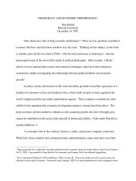
A.GearedSystems
WheneveragearedsystemsimilartothatillustratedinFigure1(a)involvinga
single gear train is to be stopped, or slowed, by a brake acting on shaft 1
rotating at speed N
1
, the kinetic energy to be dissipated in reducing the
rotational speed from N
1a
to N
1b
may be expressed in terms of the gear ratios
n
21
and the moments of inertia of each rotating member as
KE ¼
1
2
ðI
1
þ I
2
n
2
21
ÞðN
2
1
a
À N
2
1
b
Þð2-1Þ
where I
1
is the total moment of inertia of all masses rotating with shaft 1, that
is, the sum of the moments of inertia of the brake drum or disk, shaft 1 itself,
and gear 1. Similarly, I
2
represents the total moment of inertia of gear 2, shaft
2, and whatever mass rotates with shaft 2. The speed ratio n
21
is defined by
n
21
¼
N
2
N
1
ð2-2Þ
where N
1
and N
2
denote the rational speeds of shafts 1 and 2, respectively, at
any instant. In a more complicated case, as illustrated in Figure 1(b), the
kinetic energy to be dissipated in slowing or stopping the rotation is given by
KE ¼
1
2
ðN
2
1
a
À N
2
1
b
ÞðI
1
þ I
2
n
2
21
þ I
3
n
2
31
þ I
4
n
2
41
Þð2-3Þ
Acceleration Time/Heat Dissipation Calculations 153
Copyright © 2004 Marcel Dekker, Inc.
where n
41
may be written in terms of n
43
and n
31
as
n
41
¼ n
43
n
31
ð2-3Þ
In summary, the kinetic energy to be dissipated from a geared system
may be written as
KE ¼
1
2
ðN
2
1
a
À N
2
1
b
ÞðI
1
þ
X
k
i¼2
I
i
n
2
i1
Þð2-4Þ
for moments of inertia I
i
rotating at speeds ratios n
i1
relative to shaft 1, where
the brake is located.
F
IGURE
1 Brake and gear train schematic. Moments of inertia I
i
include moments
of inertia of all masses rotating with shaft i (i.e., gears and shaft itself).
Chapter 8154
Copyright © 2004 Marcel Dekker, Inc.
For simplicity the moment of inertia of most rotating mechanical com-
ponents is often given in terms of the radius of gyration r
g
, which is defined by
I ¼ mr
2
g
ð2-5Þ
where m = W/g in terms of the weight of the component and the acceleration
due to gravity, usually taken as 32.2 ft/sec
2
or 9.81 m/sec
2
.
Returning to equation (2-1), we note that if n
21
is less than 1, i.e., if N
2
is
less than N
1
, the contribution of I
2
to the kinetic energy is reduced by the
square of n
21
. Guided by this observation, we may conclude that it is generally
advantageous to place the brake on the fastest of all of the shafts involved so
that the torque requirement for the brake is reduced.
B. Combined Translation and Rotation
When translation is present, as in the case of a moving vehicle, the kinetic
energy due to linear motion must also be included to obtain the total kinetic
energy that must be dissipated by the brakes. In the case of a vehicle, if we take
the rotation of one of the road wheels as our reference, the translational
velocity is given by
v ¼ r/ ¼ rN ð2-6Þ
where f = d//dt =N is in rad/sec so that v is in terms of the units of r per
second. If the motor is not disconnected as the brakes are applied, its effect
must also be included, either as a retarder, which adds to the braking effect, or
as a driver, which opposes the brakes. In some vehicles and machines the mo-
tor may act as retarder for some operating conditions and as a driver in others.
In either event, the contribution of the motor is usually included in the W
a
term, so the energy to be dissipated in slowing from v
a
to v
b
may be written as
E ¼
1
2
N
w
I
w
N
2
þ
1
2
mv
2
þ W
a
¼
1
2
N
w
m
w
r
g
r
w
2
þ m
"#
ðv
2
a
À v
2
b
ÞþW
a
ð2-7Þ
where m represents the total mass of the vehicle and its cargo. This relation
holds if each of the N
w
wheels has a mass m
w
, a radius of gyration r
g
, and an
outside radius r
w
. W
a
is positive if it represents the work done by the motor
during braking and negative if it represents the work dissipated either by the
motor itself or by a retarder.
Although equations (2-6) and (2-7) have been discussed in terms of
vehicle motion, they apply equally well to conveyors having N
w
similar rollers
of mass m
w
, radius of gyration r
g
, and radius r.
Often, the kinetic energy due to wheel rotation is negligible compared to
the translational kinetic energy of the cargo, so that the rotational terms in
Acceleration Time/Heat Dissipation Calculations 155
Copyright © 2004 Marcel Dekker, Inc.
equation (1-10) are usually omitted from the brake selection formulas found
in a manufacturer’s catalog.
C. Braking with Changes in Potential Energy: Cranes
and Hoists
Since motion is assumed to be in the vertical direction, the energy change due
to braking or clutching when a load is either raised or lowered is the sum of the
changes in kinetic and potential energy and the work W
h
done on the system
by motors and retarders. Thus energy E may be written as
E ¼
1
2
X
k
i¼1
m
i
ðv
2
ia
À v
2
ib
Þþ
1
2
X
m
i¼1
I
i
ðN
2
ia
À N
2
ib
Þþ
X
n
i¼1
W
i
ðh
ia
À h
ib
ÞþW
a
ð2-8Þ
which is an extended version of equation (2-7) by including k masses m
i
, m
rotating components, each having moment of inertia I
i
, n weights W
ˆ
i
and their
elevation changes, and including nonzero values of velocity v
i
, and angular
rotation N
i
.
III. BRAKING AND CLUTCHING TIME AND TORQUE
Work done by a brake in slowing or stopping a mechanical system is
converted to heat at the mechanical interface in friction brakes or in the inner
and outer members in eddy-current, hysteresis, or magnetic particle brakes.
Regardless of the particular brake design, the work done is equal to
W ¼
Z
t
2
t
1
NTdt¼
Z
f
2
f
1
Tdf ð3-1Þ
where T denotes the braking torque, N=df/dt, f represents the angular
rotation of the active braking element (drum, disk, outer member), and t
denotes time.
Preliminary design or selection of a brake is often predicted on con-
stant torque, constant load, and therefore, constant deceleration. For this
condition,
N ¼ N
0
À at ð3-2Þ
so substitution into equation (3-1) with t
1
= 0 and t
2
= t yields
W ¼
Z
t
0
TðN
0
À asÞds ¼ TðN
0
À
at
2
Þt
ð3-3Þ
¼ DE ¼ DKE þ DPE þ DW
a
when time is measured from that instant when the brake was first applied. If
the brake is to stop or slow the rotation of a component, this work must equal
Chapter 8156
Copyright © 2004 Marcel Dekker, Inc.
the energy that must be dissipated in bringing that component to the new
rotational speed. Upon substitution for at from equation (3-2) into equation
(3-3), we find that
W ¼ Tt
N
0
þ N
1
2
ð3-3aÞ
Hence equation (3-3) may be written as
Tt ¼
1
x
0
þ x
1
"
X
k
i¼1
m
i
ðv
2
i
a
À v
2
i
b
Þþ
X
m
i¼1
I
i
ðN
2
i
a
À N
2
i
b
Þ
þ 2
X
n
i¼1
W
i
ðh
i
a
À h
i
b
Þþ2W
h
a
#
ð3-4Þ
If a single rotating moment of inertia I is involved, KE = (1/2) I (N
2
0
À N
2
1
)
and
T ¼ I
x
2
0
À x
2
1
ðx
0
þ x
1
Þt
¼ I
x
2
0
À x
2
1
2x
av
t
¼
I
t
ðx
0
À x
1
Þð3-5Þ
Finally, if all rotation is to be stopped, N
1
=0 and equation (3-5) becomes
T ¼
IN
0
t
ð3-6Þ
Moments of inertia for other than geometrically simple objects–such
as a solid, homogeneous cylinder–are generally given in terms of the mass m of
the rotating object when SI units are implied (i.e., kilograms) and in terms of
the weight W when OE units are implied (i.e., pounds). According to this
practice, I will be presented in terms of mass m and radius of gyration r
g
as
I ¼ mr
2
g
¼
W
g
r
2
g
ð3-7Þ
Returning now to equation (3-6), it frequently appears in design guides
in different terms. Its modified form may be found by replacing N in rad/sec by
n, the initial rotational speed in rpm, according to
N ¼
2kn
60
ð3-8Þ
and by replacing I by Wr
2
/g according to equation (3-7). The result is
T ¼ 2k
mr
2
g
n
60t
i
mr
2
g
n
10t
ðSIÞ
ð3-9Þ
T ¼ 2k
Wr
2
g
n
60gt
i
Wr
2
g
n
307t
i
Wr
2
g
n
308t
ðOEÞ
Acceleration Time/Heat Dissipation Calculations 157
Copyright © 2004 Marcel Dekker, Inc.
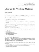
Ourpreviousdiscussionhasbeenconcernedwithbrakedesignwithout
specificknowledgeofthefrictionandheatdissipationcharacteristicsofthe
brakeasafunctionoftheslipspeed,whichistherotationalspeeddifference
betweentheengagingfacesofthebrakeorclutch.Whenthatinformationis
knownfromcatalogdata,asrepresentedbyFigure2,wecanuseit,together
withthegoverningequationofmotion,toobtainamorerealisticestimateof
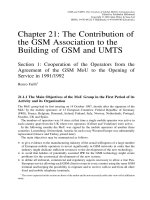
theactivationtimeandtheheatdissipatedforaviscouslydampedsystem,as
shownschematicallyinFigure3(a),wheretheviscousdampingisduetothe
processitself,orinFigure3(b),wheretheviscousdampingissuppliedbya
retarderusedtoaddtotheenergydissipatedduringstopping.Exceptforthe
brakeitself,Coulomb,ordryfriction,dampingisgenerallysuppressedinthe
remainderofthesystemandelasticeffectsaregenerallynegligible.
Fromthisfigurewefindthegoverningequationtobe
I
dN
dt
¼ÀTðNÞÀcNð3-10Þ
whereT(N)isnegativebecauseitactstoslowthemotion(i.e.,tocausedN/dtto
benegative)andwhereNdenotestheinstantaneousangularvelocityofthe
systemasitisbeingstoppedorretardedandIdenotesthemomentofinertia
ofallmassesinthesystemwhenwrittenintermsoftheangularvelocityofthe
shaftonwhichthebrakeacts.Integrationofequation(3-10)yields
t
1
Àt
2
¼I
Z
N
1
N
2
dN
TðNÞþcN
ð3-11Þ
whichrelatesthedecelerationtimetto:
1.ThenettorqueT(N),whichincludesthetorquetransferredacross
thebrake(positive),asgivenbycurvessimilartothoseshowninFig-
ure2,aswellasanytorque(negative)duetomotorsorotherdrivers
thatmaycontinuetosupplytorquewhilethebrakeisapplied
2.ThedampingcNsuppliedbyaretarded(describedinChap.11),
dampinginthesystemitself,orboth.
Inequation(3-11),Irepresentsboththerotationalandtranslationalinertia,
wherethetranslationalvelocityisexpressedintermsofNandtheappropriate
radiusaccordingtov=rN.
Equation(3-11)maybeusedtoobtainanestimateoftherelation
betweenthetorqueandthebrakingtimewheneverT(N)isknownfromdata
suchasthatshowninFigure2.Thiswillbedemonstratedinoneofthe
followingexamples.Toshowthatthisequationproducesrelation(3-6)when
thetorqueisconstant,itmaybeintegratedtogive
t
2
Àt
1
¼
I
c
ln
TþcN
1
TþcN
2
ð3-12Þ
Chapter8158
Copyright © 2004 Marcel Dekker, Inc.
F
IGURE
2 Dynamic torque as a function of the speed difference, or slip speed,
between input and output shafts. (Courtesy of Warner Electric Brake & Clutch Co.,
South Beloit, IL.)
Acceleration Time/Heat Dissipation Calculations 159
Copyright © 2004 Marcel Dekker, Inc.
which may also be written to give the required torque as
T ¼ c
N
1
À N
2
e
ðc=IÞðt
2
Àt
1
Þ
e
ðc=IÞðt
2
Àt
1
Þ
À 1
ð3-13Þ
If time is measured from the instant the brake is applied so that t
1
=0
and if the system is brought to rest so that N
2
=0, equation (3-13) simplifies to
T ¼
cN
1
e
ðc=IÞt
2
À 1
ð3-14Þ
F
IGURE
3 Schematic conveyor systems where viscous damping is due to (a) the
process itself or (b) a retarder to aid in stopping.
Chapter 8160
Copyright © 2004 Marcel Dekker, Inc.
Finally,afterexpansionoftheexponentialinequation(3-14)accord-
ingto
e
x
À1¼xþ
x
2
2!
þ
x
3
3!
þ
x
4
4!
þ:::
andsettingx=ct
2
/J,weseethat,ifcissmallenoughforc
2
tobenegligible
comparedtoc,wethenhave
T¼
cN
1
ðc=IÞt
2
þ:::
i
IN
1
t
2
ð3-15Þ
inagreementwithequation(3-6),sinceN
1
andt
2
inthisequationplaytherole
ofN
0
andtinequation(3-6).
IV.CLUTCHTORQUEANDACCELERATIONTIME
ManyoftheformulasdevelopedinSections1and2applyequallywellto
clutchapplications.Onlytheirusediffers,inthatnowtheyareusedto
determinetheworkthatmustbedonebytheclutchontheloadtoaccelerateit
totherequiredspeed.
Theequationsthatmaybeusedforeitheraclutchorabrakeare(3-4)
through(3-9).Inthecaseofaclutch,equation(3-10)isreplacedby
I
dN
dt
þcN¼TðNÞð4-1Þ
whichthenrequiresthatequation(3-11)bereplacedby
t
2
Àt
1
¼I
Z
N
2
x
1
dN
TðNÞÀcN
ð4-2Þ
astherelationbetweenthetorque,thedamping,andtheinertiaofthesystem,
bothlinearandrotational.Whenappliedtoaclutch,however,thetime
intervalt
2
Àt
1
inequation(4-2)appliestothetimeintervalrequiredforthe
clutchtobringtheloaduptospeed.Aftertheloadisatoperatingspeed,dN/dt
inequation(4-2)goestozero,sothetorqueT(N)=cNholdsaslongasthe
operatingspeedandloadareconstant(Figure4).
Whenever T is constant, differential equation (4-1) may be integrated to
give
t
2
À t
1
¼À
I
c
ln
T À cx
2
T À cx
1
ð4-3Þ
which differs from equation (3-12) only in the algebraic sign of c. Equation
(4-3) may be solved for T to get
T ¼ c
N
1
e
ðÀc=IÞðt
2
Àt
1
Þ
À N
2
e
ðÀc=IÞðt
2
Àt
1
Þ
À 1
ð4-4Þ
Acceleration Time/Heat Dissipation Calculations 161
Copyright © 2004 Marcel Dekker, Inc.
As a check on equation (4-4), note that if the clutch were applied at time t
2
=0
when N
1
=0, then equation (4-4) may be written as
T ¼ c
ÀN
2
e
ðÀc=IÞt
2
À 1
ð4-5Þ
If we again use the series expansion for e
x
given in the previous section, but
with x now replaced by Àct
2
/I we find
Ti
IN
2
t
2
ð4-6Þ
as in the case of a brake.
V. EXAMPLE 1: GRINDING WHEEL
Find the minimum torque capacity for a brake to be added to a twin-wheel
motor grinder turning at 1725 rpm such that when either guard is raised the
motor and two grinding wheels will stop within 0.1 sec. The moment of inertia
of the motor rotor is 0.0137 slug-ft and each grinding wheel weights 10 lb and
has a radius of gyration of 4.00 in.
Since all the rotating masses are on a single shaft, equation (3-6) applies,
where I represents the sum of the moments of inertia for the grinding wheels
and the rotor. From equation (3-7) we find that the moment of inertia for each
grinding wheel is
I
w
¼
w
g
r
2
¼
10
32:2
4
12
2
¼ 0:0345 slug-ft
2
ð5-1Þ
so the total moment of inertia is
I ¼ 2ð0:0345Þþ0:0137 ¼ 0:0827 slug-ft
2
ð5-2Þ
F
IGURE
4 Schematic of a typical motor, clutch, machine configuration.
Chapter 8162
Copyright © 2004 Marcel Dekker, Inc.
With the rotational speed in rad/sec given by
N ¼
2k rpm
60
¼
kð1725Þ
30
¼ 180:6416 rad=sec
substitution for I from equation (5-2) into equation (3-6) yields
T ¼
0:0827ð180:6416Þ
0:1
¼ 149:3906
f
150 lb-ft ð5-3Þ
as the required torque.
VI. EXAMPLE 2: CONVEYOR BRAKE
Recommend the torque requirement for a brake for the conveyor belt shown
schematically in Figure 5. It is rated for a total load of 180 lb (the combined
weight of all items conveyed by the conveyor). The conveyor belt weight is 50
lb, the end rollers weigh 22 lb each, and the 20 intermediate rollers weigh 4.0 lb
each. The diameter of each end roller is 8.750 in. and the radius of gyration of
each end roller is 4.0 in. The intermediate rollers are 2.00 in. in diameter and
each has a radius of gyration of 0.8 in. The reduction ratio of the gear train is
5.488, the maximum conveyor velocity is 90 ft/min, and the brake is mounted
between the driving gear motor and the gear train. The motor is disconnected
from the drive line when the brake is engaged and the conveyor is to be
stopped in the minimum time which will not cause the packages on the con-
veyor to slide along the belt. All the products to be conveyed have such a low
center of gravity that tipping is not a problem. The friction coefficient is
0.30.
F
IGURE
5 Conveyor belt schematic.
Acceleration Time/Heat Dissipation Calculations 163
Copyright © 2004 Marcel Dekker, Inc.
Kinetic energy due to rotation of the end and intermediate rollers,
translation of the belt load, and translation of the belt itself will be considered;
kinetic energy contributed by the gears and shafts in the gear train will be
ignored because their combined moments of inertia is less than that of one of
the intermediate rollers.
From equation (3-4) we find that the governing equation for a conveyor
with k
J
rotating masses and k
m
translating masses is given by
T ¼
N
0
t
X
k
J
i¼1
I
i
n
2
i
þ
d
2
n
1
2
X
k
m
i¼1
m
i
"#
ð6-1Þ
where n
i
is the ratio of rotational speed of roller i to the rotational speed of the
shaft on which the brake is mounted and d is the diameter of the drive roller,
whose speed ratio is represented by n
1
From equation (3-7) we find the moment of inertia of an end roller to be
I
e
¼ mr
2
g
¼
22
32:2
4
12
2
¼ 0:0759 slug-ft
2
ð6-2Þ
and the moment of inertia of an intermediate roller to be
I
i
¼
4:1
32:2
0:8
12
2
¼ 0:0006 slug-ft
2
ð6-3Þ
The rotational speed of the end rollers may be found from equation
(2-6) to be
N ¼
90
60
12
4:375
¼ 4:1143 rad=sec ð6-4Þ
from which it follows that the speed of the input shaft to the gear train is
N
b
¼ Nn
1
¼ 22:5792 rad=sec ð6-5Þ
for n
1
=5.488. Since the intermediate rollers that support the belt along its
length have radii of 1.00 in., their angular velocity is 18 rad/sec for an effective
speed reduction factor of 1.254 relative to the input shaft to the gear train.
Since the belt moves with the same velocity as the product being
conveyed, we can group them together so that k
m
=1+1=2. The two end
rollers and the 20 intermediate rollers give k
J
=20+2=22. With all masses
and moments of inertia known, we may substitute into equation (6-1) once we
select a stopping time t. To find the minimum stopping time without slip
between the product and the conveyor belt, recall that the stopping force of
the product is Amg, so the maximum deceleration becomes Ag. If this force is
Chapter 8164
Copyright © 2004 Marcel Dekker, Inc.
constant,thestoppingtimemaybefoundfromt=v/a=90/[60(0.3)32.2]
=0.1553sec.Substitutionintoequation(6-4)yields
T¼
22:579
0:1553
2ð0:0759Þ
5:488
2
þ
20ð0:000556Þ
1:254
2
þ
230
32:2
4:375
2
ð12
2
Þð5:488
2
Þ
!
¼6:344lb-ftð6-6Þ
¼76:130lb-in:
wheren
i
=1/5.488fortheendrollersandn
i
=1/1.254fortheintermediate
rollers.
Ifthebrakehadbeenmountedoneitheroftheendrollershafts,
equation(6-6)wouldhavebeenreplacedby
T¼
4:114
0:1553
"
2ð0:0759Þþ20ð0:000556Þð4:375Þ
2
þ
230
32:2
4:375
12
2
#
¼34:811lb-ftð6-7Þ
andthebrakingtorquerequirementwouldhavebeenn=5.488timeslarger
thanthatfoundbyequation(6-6).Thiscomparisonisanexampleofthegen-
eralrulethatthebrakeshouldusuallybeplacedinthefastershaft.
VII.EXAMPLE3:ROTARYKILN
ThecurvesinFigure6clearlyimplythatefficientuseofaclutchbyreducing
thepowerlossduetoheatgeneration,alongwithwear,requiresthatthe
speedsofitsinputandoutputshaftsshouldbenearlyequal.Accordingly,
dependinguponthepowersource(electricorhydraulicmotor,turbine,or
internalcombustionengine),aclutchmaybeusedtochangegearratios,to
changefromonepowersourcetoanotherwhenthespeedsarenearlyequal,or
todisconnectthepowersourcebeforebraking.
Thisexamplewillconsideraloadthatisessentiallyrotationalinorderto
concentrateonclutchandbrakeselectionwhendynamictorqueandbrake
heatingcurvesareavailable.Bothclutchandbrakeanalyseswilldisplaysome
ofthecalculationinvolvedwhenthespeedsoftheinputandoutputshaftsare
notalmostequal.
Arotarykilnistobedrivenbya15-hpthree-phasemotoroperatingat
870rpmandratedtodeliveratorqueof240lb-ftwithaKfactor(overload
factorforstarting)of2.64.Themotor,clutch,geartrainwitha28.4speed-
reductionratio,androtarykilnarearrangedasshowninFigure7.Theoverall
damping coefficient is approximately 0.10. The starting moment of inertia of
Acceleration Time/Heat Dissipation Calculations 165
Copyright © 2004 Marcel Dekker, Inc.