Tài liệu Clutches and brakes design and selection P12 ppt
Bạn đang xem bản rút gọn của tài liệu. Xem và tải ngay bản đầy đủ của tài liệu tại đây (470.93 KB, 21 trang )
12
Antilock Braking Systems
Antilock braking systems (also known as antiskid braking systems) for
vehicles are discussed here because they represent perhaps the most involved
commonly used systems for automatic brake control. The data collection,
analysis, and system design involved may suggest initial procedures to be
followed for clutch and brake automation in other applications.
Design of an antilock system (ABS) for highway vehicles requires de-
cisions to what is to be measured, how it is to be measured, and how to use the
data to prevent skidding. These systems are different from the early antilock
systems in that they are computer based, so they collect and process more
data.
The first patent for antilock brakes was granted in Germany in 1905 [1],
and the first antilock brakes for railroad cars were available in 1943 [2].
Electronic control of antilock brakes was widely incorporated into aircraft by
1960 [3] in order both to control aircraft skidding and to prevent excessive
wear to the tires on the landing gear of large aircraft. Although it may be
difficult to specify when the first extension to highway vehicles began, Ford
and Kelsey Hayes produced an ABS system for the rear wheels only of the
1969 Thunderbird [4]. Introduction of what was said to be modern electroni-
cally controlled ABS for passenger cars was by Daimler-Benz [5] and BOSCH
[6] in 1978.
Because of the proprietary nature of the available antiskid and traction
control systems, the latter portion of this chapter, dealing with antiskid
braking and traction control systems, will be a combination of information
from the literature and of conjecture regarding the possible techniques
available for achieving brake control.
Copyright © 2004 Marcel Dekker, Inc.
I. TIRE/ROAD FRICTION COEFFICIENT
Antilock brake control for stopping a vehicle in what is intended to be a
straight-line path clearly requires some method for detecting the skid, or slip,
of each wheel, for assimilating the data from all wheels, for analyzing this data
to estimate the vehicle’s motion, and for selecting the appropriate commands
to be sent to each wheel or set of wheels both to stop the vehicle and to
maintain stability.
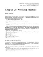
Figure 1(a) portrays the condition in which there is no slip between the
wheel and the road. Under these conditions, a wheel of radius r rotating with
angular velocity N
0
about its axis of rotation (the centerline of the axle to
which it is attached) at any instant also rotates about its instantaneous center
(the idealized point where it contacts the road as though there were no tire
F
IGURE
1 Velocity v
0
is the vehicle velocity as calculated (a) for a wheel rolling
with angular velocity N
0
without slip and (b) for rolling with angular velocity N
1
and
with slip velocity v
s
.
Chapter 12272
Copyright © 2004 Marcel Dekker, Inc.
deformation)withangularvelocityN
0
.Hence,calculationoftherotation
abouttheinstantaneouscenterrevealsthattheaxlemoveshorizontallywith
velocityv
0
,asgivenby
v
0
¼rN
0
ð1-1Þ
Ifthereisslipbetweenthewheelandtheroad,asinFigure1(b),andifv
1
denotes the velocity of the axle with respect to the point where the wheel
contacts the road, then the velocity of the axle relative to that point is given by
v
1
¼ rN
1
ð1-2Þ
where N
1
is the angular velocity of the wheel about its axis of symmetry, which
is perpendicular to the plane of the wheel. Thus, if the wheel slips with velocity
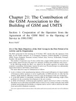
F
IGURE
2 A
B
as a function of E for (1) dry asphalt, (2) wet asphalt, thin water film,
(3) wet asphalt, thick water film, (4) fresh snow, (5) packed snow, (6) glare ice. The
positive slope of curve 4 with increasing E is due to snow build-up in front of the tire
as its rotation slows to zero.
Antilock Braking Systems 273
Copyright © 2004 Marcel Dekker, Inc.
v
s
(i.e.,thepointwherethewheelcontactstheroadmoveswithvelocityv
s
),
thenthevelocityv
0
ofthevehiclerelativetotheroadisgivenby
v
0
¼v
1
þv
s
ð1-3Þ
WheelslipduringbrakingiscommonlydescribedbytheslipratioE,as
definedby
E¼
v
s
v
0
¼
v
0
Àv
1
v
0
:ð1-4Þ
Theslipratioisfrequentlypresentedasapercentage,E(%)=100E,asin
Figure2.
For reasons that may include tire flexibility, tension and torsion of the
tread within the contact patch, and the continual replacement of material
within the tire’s contact patch, the complex nature of the tire’s contact with
the road within the contact patch means that the coefficient of friction, here
represented by A
B
, does not immediately jump from its static to its dynamic
value, as illustrated in Figure 2 [7]. That portion of each curve between E =0
and the maximum, except for curve 4, may be considered a stable region, in
that initial braking causes the friction coefficient to increase so that increased
brake pressure within this region is effective in reducing vehicle velocity. The
region beyond the maximum in A
B
may be considered a region of instability,
because, except for curve 4, increased brake pressure to further slow wheel
rotation becomes increasingly ineffective in slowing the vehicle itself due to a
decreasing friction coefficient. Returning to curve 4, its local maximum is also
followed by a region of instability, but that region is followed by a stable
region caused by the build up of snow in front of the wheel as its rotation
slows.
II. MECHANICAL SKID DETECTION
Early antilock braking systems used annular disks that were friction driven to
rotate with each wheel during normal acceleration and deceleration but that
would slip as frictional resistance was overcome during abnormal or panic
breaking, as a means of detecting wheel deceleration. Whenever the wheel
would decelerate beyond a certain threshold, the disk that was concentric with
it would continue rotating and thereby trip some mechanism that would
reduce brake pressure. This technique, or a modification of it, was the only
practical means of detecting wheel deceleration prior to the introduction of
microprocessors. It was also relatively inexpensive and therefore its use
continued through 1968, and perhaps beyone, for some inexpensive European
Chapter 12274
Copyright © 2004 Marcel Dekker, Inc.
automobiles.AnexamplewastheLucasGirlingStopControlSystem(SCS),
whichisexplainedintheparagraphsbelowFigures3–5,takenfromRef.8,
which describe the modulator. It was designed for front wheel drive (FWD)
vehicles and employed only two modulators, one on each front wheel. Each
modulator controlled its front wheel and the diagonally opposite rear wheel
through a proportioning valve, as required by European regulations. Dis-
played components in these figures are
1. Drive shaft
2. Flywheel
3. Flywheel bearing
4. Ball and ramp drive
5. Clutch
6. Flywheel spring
7. Dump valve
8. Dump valve spring
F
IGURE
3 Flywheel and valve positions for the Lucas Girling SCS during normal
braking.
Antilock Braking Systems 275
Copyright © 2004 Marcel Dekker, Inc.
9.Dumpvalvelever
10.Eccentriccam
11.Pumppiston
12.Pistonspring
13.Cutoffvalve
14.Deboostpistonspring
15.Deboostpiston
16.Cutoffvalvespring
17.Pumpinletvalve
18.Pumpoutletvalve
SincethetextbeloweachfigurewasreproduceddirectlyfromRef.8.Figures9
and10mentionedinFigure4correspondtoFigures3and5asreproduced
here.
Allsystemsusingrotatingdisksthatmustmoveaxiallytoengagethe
brakecontrolmechanismarehandicappedbythetimerequiredtoaccelerate
F
IGURE
4FlywheelandvalvepositionsfortheLucasGirlingSCSduringpanic
braking.
Chapter 12276
Copyright © 2004 Marcel Dekker, Inc.
themassofthedisklaterallyovertherequireddistances.Thisrelationshipis
qualitativelysimilartothatforthedistancetraveledbyamassmthatis
acceleratedfromrestbyaforceFovertimet:
x
s
¼
F
2m
ðx;yÞ
2
ð2-1Þ
wherex(0VxVs)isthatportionofdistancestraveledduringtimet
(0VtVH),wheretisthecorrespondingportionoftheactivationtimet(see
Figure6).Thus,inthefirsthalfoftherequiredtime,themasshasmovedonly
one-fourthoftherequireddistance.
Fasterresponsemaybehadbyusingelectricalwheel-speedsensorsthat
measurewheelspeedandsendthatdatatoasmall,dedicatedcomputer
knownasanelectroniccontrolunit,oranECU.
F
IGURE
5FlywheelandvalvepositionsfortheLucasGirlingSCSduringreturnto
normal braking.
Antilock Braking Systems 277
Copyright © 2004 Marcel Dekker, Inc.
III.ELECTRICALSKIDDETECTION:SENSORS
Developmentofrelativelyinexpensivemicroprocessors,accelerometers,and
electromagneticwheel-speedsensorsthatcouldbeincorporatedintoauto-
motivecontrolspermittedmoreprecisemeasurementofwheelspeedand,
hence,vehiclespeed,acceleration,anddecelerationalongwithrapiddetection
ofandimprovedresponsetoindividualwheeldecelerationassociatedwith
wheelskid.
Additionofasmalldedicatedcomputerknownasanelectroniccontrol
unti,oranECU,toanantilocksystemallowsthecorrelationofdatafrom
wheel-speedsensorsoneachofallfourwheelsintoapreprogrammeddecision
andcontrolprocess.Presentlyeachwheel-speedsensorconsistsoftwo
components:apermanentbarmagnetwithacoilofwirewrappedaround
itandasensorring,asshowninFigure7.Thesensorringrotateswiththe
F
IGURE
6Graphofx/sasafunctionoft/Hfromequation12-1.
Chapter 12278
Copyright © 2004 Marcel Dekker, Inc.