Tài liệu Steady State Operation of DC Machines pptx
Bạn đang xem bản rút gọn của tài liệu. Xem và tải ngay bản đầy đủ của tài liệu tại đây (91.57 KB, 12 trang )
ENGNG2024 Electrical Engineering
E Levi, 2001
1
STEADY STATE OPERATION OF DC MACHINES
1. INTRODUCTION
Electric DC machines, as indeed any other type of electric machine, can be used to
either produce electric energy from the input mechanical energy, or to convert electric energy
into output mechanical energy. These two possible operating regimes are called generation and
motoring. As already mentioned, DC machines used to be in the past the major source of DC
power. In order to produce electric power DC machines were operated as generators.
Nowadays, however, use of DC generators is becoming more and more rare. DC power is
obtained instead by means of power electronic converters. The remaining applications of DC
machines are today restricted to motoring. In this operating regime a DC machine is operated
as a DC motor: it consumes DC power, while delivering at its shaft mechanical power. The
shaft drives a certain load, that is characterised with the load torque.
A DC machine consists of stationary part, called stator, and rotating part, called rotor.
Both stator and rotor are equipped with one winding. Stator winding is supplied from a DC
voltagesourceandtheroleofthiswindingistoproducemagneticfluxintheairgapofthe
machine. This flux is stationary in space. Rotor winding is again supplied from a DC voltage
source (for motoring): DC supply is connected to the rotor winding through a special
assembly, that is composed of brushes and commutator. Brushes are stationary, while
commutator is fixed to the rotor and hence rotates together with the rotor. This assembly
enables supply of electric power from stationary power supply to rotating winding on rotor.
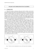
Principle of operation of this assembly is illustrated by means of Fig. 1. Rotor winding is shown
in a very simplified manner, as consisting of just one coil, connected to two segments of the
commutator. Motoring action is assumed and the current is therefore delivered to the rotor
winding through the stationary brushes and rotating commutator. Two positions of the rotor
winding are shown in Fig. 1. Terminal current (current brought to the brushes) and the winding
current are illustrated in Fig. 2. As can be seen from these two figures, current inside the rotor
winding is reversed (commutated) after each half-revolution of the rotor. Current inside the
rotor is therefore AC, while the terminal current is DC. Frequency of the current inside the
rotor winding equals frequency of rotation.
θ
A
i
a
=I
a
i
a
i=I
a
B
θ
B
i
a
=I
a
i
a
i=−I
a
A
Fig. 1 - Current reversal (commutation) in rotor coil by means of the commutator.
ENGNG2024 Electrical Engineering
E Levi, 2001
2
i
a
I
a
iI
a
0 θ = ωt0π 2πθ=ωt
−
I
a
Fig. 2 - Terminal current and current through rotor coil.
Note that such a situation regarding frequencies in the two windings is the only possible
one that satisfies the condition of average torque existence. Since the stator winding is supplied
with pure DC current of zero frequency, the machine can develop an average torque if and
only if the rotor winding frequency equals the frequency of rotation. This means that it is not
possible to realise an electric machine with DC currents flowing in both stator and rotor
windings. Such a situation would result in the possibility of developing an average torque at
zero speed only. At zero speed however converted power equals zero and therefore such a
machine could not do the process of electromechanical energy conversion.
Let the stator winding, which is called excitation or field winding as well, be supplied
with constant DC voltage equal to V
f
. Current that flows through this winding is in steady-
state operation determined with
I
f
=V
f
/R
f
(1)
Flux produced in the air gap of the machine is, neglecting saturation of the magnetic circuit,
proportional to this current. Hence
Φ
f
= c
1
I
f
(2)
It has to be emphasised that the excitation winding can be replaced with permanent magnets.
Many of the modern DC motors rely on permanent magnet excitation and in such a case there
is not any possibility of changing the excitation flux, since it is fixed by the magnet properties.
Rotor rotates at certain angular speed ω [rad/s], in the stationary flux produced by the
excitation winding. Thus, according to the basic law of electro-magnetic induction, e=Blv
(where v is linear speed, B is flux density and l is length of the conductor), there is an induced
electromotive force (emf) in the rotor winding
E = c
2
Φ
f
ω = kI
f
ω (3)
Induced emf is proportional to the flux (i.e., excitation current) and to the speed of rotation,
through a constant determined with constructional features of the machine. Speed of rotation ω
is the so-called angular speed of rotation in [rad/s] and it is correlated with the speed n in
revolutions per minute [rpm] through
()
ωπ
= 260n
. As rotor winding (often called armature
winding) is supplied from a DC voltage source and as the winding is of certain resistance, then
the voltage equilibrium equation for the armature winding (index a)is
V
a
=R
a
I
a
+E (4)
According to the basic law of electromagnetic force creation, if a conductor that carries
current I moves in the flux of flux density B, then an electromagnetic force F=BIlacts on
the conductor. As rotor winding rotates in the flux density produced by the excitation winding,
an electromagnetic torque is produced, equal to
T
e
=c
2
Φ
f
I
a
=kI
f
I
a
(5)
This electromagnetic torque is the reason why the rotor rotates. If there is load connected to
the shaft of the machine, then this load opposes rotation with its torque, called load torque T
L
.
ENGNG2024 Electrical Engineering
E Levi, 2001
3
In any steady-state condition electromagnetic torque and load torque are equal and act in the
opposite direction. While electromagnetic torque acts in the direction of rotation, load torque
acts in the opposite direction, as illustrated in Fig. 3 for two possible directions of rotation, and
expressed with the following relation:
T
e
=T
L
(6)
Angular speed of rotation in [rad/s] is correlated with speed in [rpm] through the
already given scaling factor
n [rpm] = (60/2 π) ω [rad/s] (7)
T
e
T
e
ωω
rotor rotor
T
L
T
L
forward motoring reverse motoring
Fig. 3 - Directions of electromagnetic torque, load torque and speed in motoring.
Note that constant of proportionality in expressions for induced emf and
electromagnetic torque, k, is the same as long as speed in expression for emf is given in rad/s.
Input and output powers of the motor are electrical and mechanical powers,
respectively, and are given with the following expressions:
P
in
=V
a
I
a
+ V
f
I
f
(8)
P
out
=T
e
ω (9)
The difference of the two powers represents power loss in the machine, which includes
mechanical loss, iron loss and loss in the windings. In what follows mechanical loss and iron
loss will be frequently neglected, but copper loss will always be accounted for. Power loss in
the machine and the efficiency are given with
P
loss
=P
in
-P
out
(10)
η
=P
out
/P
in
(11)
Equations (1)-(11) completely describe steady-state operation of a DC motor. Standard data
that are given for a DC motor on its nameplate are so-called rated values of output power,
armature voltage and current, excitation voltage and current, and speed of rotation in rpm.
Rated values will always be identified in examples with index n. Note that, as rated power is
always output power, rated power for a motor is mechanical output power.
Load torque that an electric motor drives can be either speed independent (say, crane
lifting a load) or speed dependent. Frequently met speed dependent load torques are either
linearly proportional to speed or proportional to speed squared (pumps, compressors, fans,
etc.). These three types of load torques are illustrated in Fig. 4. If the load torque is constant,
then it follows from (5) that product of excitation current and armature current is constant as
well. This is the simplest case and all the examples will assume that a DC motor drives a
constant speed independent load torque.
Depending on how excitation winding and armature winding are supplied from DC
voltage sources, various types of DC motors may be identified. Two of the types that are
nowadays in wide application are separately excited DC motor and series excited DC motor.
The third one, rarely used nowadays, is the shunt excited DC machine. In a separately excited
ENGNG2024 Electrical Engineering
E Levi, 2001
4
DC machine, two voltage DC sources are used. Shunt and series excited DC machines require
only one voltage source, with the stator and rotor winding connected in parallel and in series,
respectively. These three DC machine types are considered in more detail in what follows.
T
L
=kω
T
L
T
L
=const.
T
L
=kω
2
ω
Fig. 4 - Illustration of various types of load torques.
2. SEPARATELY EXCITED DC MOTOR
Excitation winding and armature winding of a separately excited DC motor are
supplied from two independent DC power sources. A separately excited DC motor is described
in steady-state operation with the following set of equations, that essentially only summarise
again (1)-(6)
VERI
VRI
cI
Ec kI
Tc I kII
TT
aaa
fff
ff
ff
efafa
Le
=+
=
=
==
==
=
Φ
Φ
Φ
1
2
2
ωω
(12)
Equivalent circuit of a separately excited DC motor is shown in Fig. 5. Mechanical, speed-
torque characteristic of the motor (speed against electromagnetic torque) can be derived from
(12) as follows:
()
()
V E R I kI R I I V kI R
TkII kIVkI R
V
kI
R
kI
T
IVR
V
kI
R
kI
T
aaafaaaafa
efafaf a
a
f
a
f
e
fn fn f
an
fn
a
fn
e
=+ = +
Þ
=−
== −
=−
=
=−
ωω
ω
ω
ω
()
()
2
2
If both voltages have rated values then
(13)
Speed-torque characteristic, with rated voltages applied to both windings, is the so-called
natural operating characteristic and is shown in Fig. 5 with bold trace. Equation (13) enables
examination of available speed control methods for a separately excited DC motor, that are
beyond the scope here. As can be seen from the speed torque characteristic, speed slightly
decreases, in a linear manner, as load is increased. The highest value of the operating speed is
under no-load conditions (i.e., load torque equal to zero). Rated operating point is indicated in
ENGNG2024 Electrical Engineering
E Levi, 2001
5
Fig. 5 as well. Speed drop in a separately excited DC machine from no-load condition to full
(rated) load conditions is typically a few tens of rpms.
Example 1:
A separately excited DC motor has the following rated data: 500 V, 100 A, 1000 rpm.
Armature resistance is 0.5 Ω. Excitation flux is constant and equal to rated. Calculate
rated torque and rated power of the motor and evaluate efficiency of the motor in the
rated operation if power loss in the excitation winding is 5 kW.
Solution:
As rated voltage and rated armature current are known, then from (12) one can calculate induced
electro-motive force in rated operating conditions:
ERI EV RI x
EkI kI n kI
E
n
x
TkII x
PT x x
PP
an naan nanaan
nfnnfn n fn
n
n
en fn an
nenn
nnin
=+
Þ
=− =− =
==
Þ
== =
== =
== =
== += =
500 0 5 100 450
2
60
2
60
30 450 1000 4.3
4.3 100 430
430
2
60
1000 45030
45030 50000 5000) 4503 55
.
/( )
//( ./
V
Rated torque is then
Nm
Rated power is mechanical (output)power,
W
Input power is the power delivered to the armature winding (500 V times 100 A)
plus the power delivered to the excitation winding (5 kW). The efficiency in rated
operation is ratio of output to input power. Hence
ω
π
π
π
ω
π
η
0819.
Example 2:
Separately excited DC motor, 230 V, armature resistance = 0.2 Ω,operatesunder
no-load conditions at 1200 rpm. Under rated conditions armature current is 40 A.
Find the rated speed and rated electromagnetic torque of the motor. Excitation flux is
constant and rated.
Solution:
Speed is in this example known for no-load operating conditions. If there is not load connected to
the shaft of the motor, then load torque is zero. From (12) it follows that electromagnetic torque is
zero as well. As electromagnetic torque is proportional to the armature current, then zero torque
indicates that armature current is zero. No-load point is denoted with index ‘0’. Hence
EV RI V
EkI n kI
E
n
V
n
x
EV RI x
EkI n n
E
kI
x
TkII x
an a a an
fn fn
an
nanaan
nfnnn
n
fn
en fn an
00
00
0
00
2
60
2
60
2
60
30 230 1200 183
230 0 2 40 222
2
60
2
60
30 222 183 1150
183 40 732
=− =
=
Þ
=== =
=− =− =
=
Þ
== =
===
π
ππ
π
π
π
π
/( ) .
.
/(. )
..
Then for rated operating conditions
V
rpm
Nm