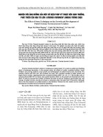
Nghiên cứu ảnh hƣởng xoáy lốc của dòng khí nạp đến công suất động cơ trên xe máy honda future FI 125
Bạn đang xem bản rút gọn của tài liệu. Xem và tải ngay bản đầy đủ của tài liệu tại đây (1.36 MB, 25 trang )
HCMC UNIVERSITY OF TECHNOLOGY AND EDUCATION
THE EFFECTS OF TURBULENT AIRFLOW ON ENGINE PERFORMANCE IN HONDA
FUTURE FI 125cc
Advisor : Dr. Ly Vinh Dat
Members: Thich Tan Do ID: 13145248
Vu Van Tran ID: 13145335
OUTLINES
HCMC UNIVERSITY OF TECHNOLOGY AND EDUCATION
1
OVERVIEW
2
THEORETICAL BASIS
3
MODELING APPROACH
4
RESULTS AND DISCUSSION
5
July 28, 2017
CONCLUSION
1
1.OVERVIEW
HCMC UNIVERSITY OF TECHNOLOGY AND EDUCATION
1.1 Motivation
July 28, 2017
2
1.OVERVIEW
HCMC UNIVERSITY OF TECHNOLOGY AND EDUCATION
1.1 Motivation
Large companies have constantly changed the technology to
meet this demand.
The combustion process in the motorcycle engine needs to
be improved to reduce fuel consumption and increase
efficiency.
July 28, 2017
3
1.OVERVIEW
HCMC UNIVERSITY OF TECHNOLOGY AND EDUCATION
1.2 The target
Build mathematical models and simulation engine models.
Examine the effects of swirl and tumble in intake manifold on engine performance
Propose a new improved intake manifold design for the engine optimization.
July 28, 2017
4
1.OVERVIEW
HCMC UNIVERSITY OF TECHNOLOGY AND EDUCATION
1.3 The object
Mathematical model in engine simulation.
The focus on the charging system, intake manifold shape
(Future FI 125).
Swirling the airflow in the engine combustion chamber.
Software tools are supported by Matlab, CATIA and ANSYS.
July 28, 2017
5
1.OVERVIEW
HCMC UNIVERSITY OF TECHNOLOGY AND EDUCATION
1.4 The research scope
Study the effects of air flow turbulence on engine performance
Build motorcycle engine model that simulate actual engine cycles with various swirls and tumbles
The new design of intake manifold shape after using ANSYS compared with Matlab /Simulink for
optimizing the desired results.
Find out the optimal air flow turbulence for engine performance
July 28, 2017
6
2.THEORETICAL BASIS
HCMC UNIVERSITY OF TECHNOLOGY AND EDUCATION
2.1 The simulation methods
Quasi-steady model.
Filling and emptying model.
Wave action model.
CFD model.
July 28, 2017
7
2.THEORETICAL BASIS
Filling and emptying methods
Air mass rate through manifold head
Intake manifold
m&ϕ = ACd d ( pm , p0 )
n
dpm RT
&
&
=
m
−
m
∑
ϕ
ri
dt
Vm
i =1
Intake runner
Air mass rate through intake valve
m ci ,in = Aiv ( Liv )d ( pci , pri )
dpri RTin
=
( m ri − m ci )
dt
Vri
9
2.THEORETICAL BASIS
HCMC UNIVERSITY OF TECHNOLOGY AND EDUCATION
Filling and emptying model was builed Matlab Simulink
July 28, 2017
10
3. MODELING OF ENGINE
HCMC UNIVERSITY OF TECHNOLOGY AND EDUCATION
Fact Modeling
July 28, 2017
12
3. MODELING OF ENGINE
HCMC UNIVERSITY OF TECHNOLOGY AND EDUCATION
Parameters
Value
Unit
Connecting rod Length
101.5
mm
Intake Pressure
140
Pa
Bore
52.4
mm
Clearance Volume
15
Cm^3
Crankshaft Radius
28.95
mm
Intake Manifold Diameter
23.2
mm
Compression Ratio
9.3
Valve Number
2
July 28, 2017
11
3. MODELING OF ENGINE
HCMC UNIVERSITY OF TECHNOLOGY AND EDUCATION
Designed by CATIA software
Intake manifold and Exhaust manifold.
Intake valve and Exhaust valve
Cylinder Head.
July 28, 2017
13
3. MODELING OF ENGINE
HCMC UNIVERSITY OF TECHNOLOGY AND EDUCATION
July 28, 2017
14
3. MODELING OF ENGINE
HCMC UNIVERSITY OF TECHNOLOGY AND EDUCATION
Set Parameters
July 28, 2017
15
4. RESULTS & DISCUSSION
HCMC UNIVERSITY OF TECHNOLOGY AND EDUCATION
4.1 Meshing
After simulating, we have the meshing process as
picture.
July 28, 2017
16
4. RESULTS & DISCUSSION
HCMC UNIVERSITY OF TECHNOLOGY AND EDUCATION
4.2 Velocity Spectrum
The maximum value of velocity is 270 m / s.
July 28, 2017
17
4. RESULTS & DISCUSSION
HCMC UNIVERSITY OF TECHNOLOGY AND EDUCATION
Swirl Ratio
Intake manifold 25
o
Intake manifold 30
Intake manifold 35
July 28, 2017
o
o
18
4. RESULT AND COMMENT
HCMC UNIVERSITY OF TECHNOLOGY AND EDUCATION
Tumble Ratio
Intake manifold 25
Intake manifold 30
o
Intake manifold 35
July 28, 2017
o
o
19
4. RESULT AND COMMENT
HCMC UNIVERSITY OF TECHNOLOGY AND EDUCATION
4.4 Power
July 28, 2017
20
4. RESULT AND COMMENT
HCMC UNIVERSITY OF TECHNOLOGY AND EDUCATION
4.5 Torque
July 28, 2017
21
4. RESULT AND COMMENT
HCMC UNIVERSITY OF TECHNOLOGY AND EDUCATION
4.6 SFC
July 28, 2017
22
5. CONCLUSIONS
HCMC UNIVERSITY OF TECHNOLOGY AND EDUCATION
The 30 degree angle is optimal because:
Swirl Ratio and Tumble Ratio are highest.
Power and moment are highest.
SFC is lowest.
Technology
Economy
Environment
July 28, 2017
23
5. CONCLUSIONS
HCMC UNIVERSITY OF TECHNOLOGY AND EDUCATION
From simulating a single-cylinder engine, we can extend the application of this software to simulate a more cylinder
engine and complex engine.
We can make a variable-angle intake manifold.
We can make a flip-flop valve to vary the swirl ratio and tumble ratio according to the engine speed.
July 28, 2017
24
HCMC UNIVERSITY OF TECHNOLOGY AND EDUCATION
25