Tài liệu ADC KRONE Network News - Vol.09 No.1 - 2002 pdf
Bạn đang xem bản rút gọn của tài liệu. Xem và tải ngay bản đầy đủ của tài liệu tại đây (486 KB, 16 trang )
NETWORK
news
February/March 2002
Vol 9 No1
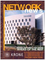
DEAKIN UNIVERSITY AND KRONE
AHEAD OF THE REST
N
owhere is that reflected more than
in Fran Towey’s personal account
on page 4 of how the team at KRONE
Americas pitched in to help their
customer, Verizon Commun-ications,
after the September 11 tragedy in New
York city.
Verizon’s loyalty to the use of KRONE
products stems back to 1992 when
KRONE products survived major storm
flooding in Wall Street, resulting in the
telecomunications giant standardising
on our product. Again, we came to the
rescue with support and service after
the 1993 World Trade Centre bombing left
Verizon with more outages.
KRONE Australia has often been asked to help
out our customers in emergencies - whether
they are fire, flood, network failures or other
incidents. One of the most dramatic examples
was in January, 1995, when our subsidiary office
in Tokyo was called on to help Japan’s telco, NTT,
after the traumatic Great Hanshin earthquake
devastated the people and environment of
Kobe. In the midst of destruction, the KRONE
LSA-PLUS products installed in Kobe withstood
the violent shaking of the earthquake. With
these network foundations still in place, KRONE
was able to work with authorities to help
corporations re-establish their communications
with a minimum of fuss.
We continue to use the same LSA-PLUS core
technology today - the difference being that our
products are constantly evolving to meet the
increases in bandwidth demanded by our
customers.
Club KRONE was established in 1998 to add
value to the products and solutions we provide to
our installer customers and Peter Davis tells how
we have enhanced the Club’s offerings in 2002.
See how our end-user customers, Deakin
University and Westinghouse Signals, have
benefited from the solutions we have developed
for their particular needs.
We make it our business to keep our
customers informed by issuing regular updates
on industry regulations and standards via
Network News, Club KRONE or our website.
KRONE’s training courses offer certification in
structured cabling and optical fibre as well as
more advanced programs for Master Cabler and
Master Designer qualifications.
To enhance our productivity so we can provide
better service for our customers we have made a
significant investment in a new Cisco IP
telephony system. It will be business as usual
during the changeover in February - see Rob
Milne’s article on page 15 for more details.
If you have problem and need a solution, call
us. It’s all part of the service.
Sincerely ...
Craig Jones
CEO
2
NETWORKnews
Our customers are our business and we are committed to going that
extra length to provide service and support.
Front cover image by Simon Peter Fox, Senior photographer Deakin University
MORE THAN A MANUFACTURER
ALWAYS COMMITTED TO HELPING OUR CUSTOMERS
Business Articles
10 Is Fibre to the Desk Becoming
a Reality?
Customer Stories
3 Redcliffe Goes Platinum
8 Deakin University Stays Ahead of
the Rest with TrueNet
12 Getting the Signals Right for
NSW RIC
KRONE News
4 Pitching in to Help US telco,
Verizon
5 Club KRONE: Partnering For Best
Results
6 A Pictorial Tour of our Berkeley
Vale Plant
15 IP Telephony system Enables
Future Technology
16 Club KRONE
Product Watch
11 Carriers or Commercial, KRONE
Cables Suit all Needs
Standards and Industry News
14 New Backbone Cabling Rules
Mean Design is Crucial
Website: www.krone.com.au
Email:
CONTENTS
Copyright © 2001 KRONE Australia Holdings Pty. Limited
W
e are committed to providing incentives
and information that will enable our
KRONE installers to build their businesses and
better service their customers.
Right from the start, the programme was
unique to the industry in that it is not a lottery:
the day members start spending is the day they
start to benefit.
Installers simply purchase KRONE voice and
data products from any of KRONE’s authorised
distribution outlets around Australia to begin to
acquire Club KRONE points.
The products or bonuses given on redemption
of points are relevant to our customer’s business,
not token gestures to store on the mantelpiece.
Past promotions offered bonus KRONE product
and points also could be redeemed against
KRONE training sessions.
Distributors have also benefited substantially
from the scheme, enjoying new business
opportunities as more installers have become
involved.
Last year we launched the Club KRONE
website and, in a recent survey, all members
were aware of the website with the majority
visiting the site regularly.
More and more, we are seeing members use
the website to redeem points. “ It makes life so
much easier,” says Pat Dillon of Bendigo Voice
and Data. “ I don’t have to calculate how many
points I have left. The system simply recalculates
as I mark off the selected items.”
One of the most significant benefits for
KRONE is that the Club enhances our
relationship with members enabling us to gain
valuable feedback, which we apply when
developing new products or reviewing our Club
KRONE offerings.
We have applied this information to
redesigning the Club KRONE website. The new
format for 2002 makes it easier to use and
incorporates a host of additional benefits such as
the Frequently Asked Questions section, or the
Cablers’ Forum which enables you to post or
reply to questions about KRONE products and
any other communications-related topics (see
more features on page 16).
Let us know what you think and, if you’re not
a member - or your membership is inactive, now
is the time to move.
COME AND VISIT OUR
MANUFACTURING FACILITY
One of the unique benefits of purchasing
KRONE product is the surety of supply, product
functionality and quality, R&D, logistics and
environmental factors. For 20 years we have
been the only telecommunications connectivity
manufacturer located in Australia.
Some of you have already visited our plant at
Berkeley Vale on the NSW Central Coast. It’s
impressive and we’re proud of it and the industry
awards we have won. For those who haven’t
been our guests for a factory tour because of
time and work constraints, we thought we’d
take you on a virtual tour starting on page 6.
NETWORKnews
3
by Peter Davis
Sales and Marketing
Manager
KRONE Australia
PARTNERING
FOR THE BEST RESULTS
It’s four years since we introduced Club KRONE and it has proved a
boon for our active members. We started with a handful of active
members in 1998 and it’s gratifying to see that figure has grown well
beyond our expectations.
Distributors have also benefited
substantially from the scheme,
enjoying new business
opportunities as more installers
have become involved.
4
NETWORKnews
D
esign of backbone cabling is often in the
shadow of horizontal cable design, but the
need for reliable high speed data transmission will
bring backbone design to the fore. Changes to
cabling standard AS/NZS 3080 later this year will
show a structured approach to backbone lengths.
The physical topology of the backbone cabling
will remain as the current Star topology, but the
backbone channel lengths and the class of
application to be supported will determine the
selection of balanced hardware components.
The backbone channel, either building or
campus, is deemed to contain a cross-connect at
each end and, so, represents the maximum four-
connector configuration for class D, E, or F as a
backbone (as opposed to a horizontal channel).
The backbone channel includes additional
cords comprising patch cord/jumpers and
equipment cords. The assumptions are that:
1. the flexible cable within these cords may have
a higher insertion loss than that for solid cable
used in the backbone; and
2. all the cords in the channel have a common
insertion loss specification.
In order to accommodate the higher insertion loss
of the patch cords/ jumpers, and equipment cords;
the length of backbone links must be reduced
according to the class of backbone link and the
category of components used to make up the link.
Additionally, two general restrictions apply:
1. the physical length shall not exceed 100 metres
for Class D, E, and F backbone channels; and
2. when four connections are used in the
channel, the minimum backbone link should be
15 metres.
The maximum length of backbone channels
will depend on the total length of cord to be
supported within the channel. The maximum
lengths of cord shall be set during the design
phase and a management system is required to
ensure that these lengths are not exceeded
during the subsequent operation of the cabling
system after initial installation.
However, where channels contain more or less
than four connectors, the backbone length must
be reduced (where more connectors exist) or
may be increased (where less connectors exist)
by two metres per connector for category 5E
components and one metre per connector for
category 6 and 7 components. Also, for
operating temperatures above 20°C, backbone
link lengths should be reduced by 0.4% per °C
for UTP cables.
The way to achieve maximum length and
maximum performance out of your backbone
design is to reduce insertion loss by (a) the use of
HIGHBAND modules at each end and (b) by the
use of KRONE Patch By Exception (PBE)
methodology. The table of backbone link lengths
(see below), shows that the length must be
reduced by a factor of x, dependant on the
combined lengths of patch/jumper and
equipment cords, and the use of stranded
cordage. Using KRONE’s PBE and factory-tested
LAN leads for equipment cords mean that X=0
and no de-rating of length is necessary.
Take the opportunity to update your skills
and knowledge, by undertaking a KRONE
Training Course. For details, visit our website
at www.krone.com.au and look under the
Training section.
Changes to Backbone Cabling standards necessitate accurate design
work well before getting on site.
NEW BACKBONE CABLING RULES
MEAN DESIGN IS CRUCIAL
Class
Component
AB C D E F
Category
5E 2,000 250 - FX 170 - FX 105 - FX
6 2,000 260 - FX 185 - FX 111 - FX 102 - FX
7 2,000 260 - FX 190 - FX 115 - FX 104 - FX 102 - FX
F = Combined length of patch/jumper and equipment cords, in metres
X = Ratio of patch cord cable insertion loss dB/m to backbone cable insertion loss dB/m. In Europe this ratio is usually 1.5
FD or BD
BD or CD
EQP
c c c
Equipment
cord
Patch cord/
Jumper cable
EQP
c c c
Equipment
cord
Patch cord/
Jumper cable
Backbone Channel
Backbone Cable
BD or CD
FD or BD
EQP
EQP
Patchcord/
Jumper cable
Equipment
Cord
Equipment
Cord
Patchcord/
Jumper cable
c
c
c
c c
c
Backbone
Link
Lengths
(m)
By Peter Meijer
JP BE MSc
Technical Training
Manager and
Industry Liaison, KRONE
Australia
Backbone
cabling
model
NETWORKnews
5
G
enerally, in today’s installations copper is
used for horizontal distribution and fibre
connects the closets to the main equipment
room. Clearly, this makes sense given the high
bandwidth available in fibre and its smaller size
(which enables easy routing between closets).
Because backbone capacity should be greater
than desktop capacity, and since desktops have
only recently been making the wholesale switch
to 100BASE-T, the migration to a fibre Gigabit
Ethernet backbone is on the horizon. As 1000
BASE-T to the desktop becomes widespread, the
next natural progression will be to a 10Gbps
fibre backbone. In fact, at this stage, fibre is the
only cabling medium recognised in the draft
standard for 10Gbps Ethernet.
‘FIBRE TO THE ZONE’ AND BEYOND
The growth in demand for more bandwidth will
see fibre deployed out to particular zones (or
departments) within the building with copper
running from the zone to the desktop. A key
factor in this scenario is the capability to
remotely manage switched hubs (switches); no
longer will IT personnel need to physically check
each port in each closet.
The Fibre to the Zone configuration enables
the network manager to place active devices
closer to the users - either to smaller,
intermediate telecom closets or even to small,
lockable enclosures near the workgroup. Since
switches are now available with fibre uplinks
and
copper ports, it may be that one device will
suffice per workgroup.
This strategy works especially well for large,
open office cubicle groups or for very large work
areas that have poorly spaced telecom closets.
Fibre to the Zone also is relatively cost-effective
since traffic back to the main closet is
aggregated over just two fibres. In fact, utilising
just two fibres from the zone consolidation point
would eliminate the need to run an individual
copper link from each workstation to the closet.
If, in the future, the client decides to
implement fibre-to-the-desk (FTTD) there will
already be a fibre backbone out to the
workstation zone. Replacing the short runs to
the zone enclosure will be far easier and more
cost effective than replacing entire copper links
back to the closet to implement FTTD.
We anticipate the deployment of these fibre-
extending strategies to be sporadic due to cost
factors. An all-fibre network (FTTD) is the most
expensive alternative because of the higher cost
of fibre network interface cards (NICs) and
optical switch ports. On the other hand, Fibre to
the Zone costs are lower than FTTD because of
the utilisation of copper hub ports and NICs.
Fibre to the Zone puts companies one step
closer to the ultimate upgrade: Fibre to the
Desktop. Copper, however, is well and truly the
preferred medium for horizontal structured
cabling installations.
Personally, I do not see this changing in the
very near future until the cost of fibre cabling
and connectivity reduces to the level of a copper
solution. By then, copper may well be supporting
10 gigabits.
IS FIBRE TO THE DESK
BECOMING A REALITY?
By Trevor Kleinert,
National Sales Manager
and Business
Development Manager -
Fibre, KRONE Australia
Fibre to the Zone puts companies one step closer to the ultimate upgrade:
Fibre to the Desktop. Copper, however, is well and truly the preferred
medium for horizontal structured cabling installations.
Inter-building cabling
Intra-building cabling
6
NETWORKnews
Tool Room 3
〈〈〈
Assembly 9
〈〈〈
K
RONE Australia’s 10,000
square metre head office
and manufacturing facility is
located at Berkeley Vale on
the NSW Central Coast. We
are accredited to ISO9001
(quality management system)
and ISO 14001 (environmental
management system) and in
2000 and 2001 received three
excellence awards from the
Australian Electrical and
Electronic Manufacturers’
Association and two special
commendations.
Through our world-class R&D
department and laboratory,
we design and develop more
than 75% of the KRONE
group’s regional product
range and 90% of the
Group’s range for our local
market. Our R&D Lab has
received accreditation from all
major local and global
authorities including the
Australian Communications
Authority (ACA), the
International Standards Org-
anisation (ISO), Standards
Australia and the prestigious US
Underwriters Laboratory (UL).
We use three manu-
facturing disciplines: injection
moulding; metal stamping,
high-speed automation and
robotics. The plant operates
24 hours a day, six days a
week.
Our R&D, manufacturing,
engineering and toolroom
often work on projects
concurrently to minimise
production time.
The state of the art and
manufacturing facility at
Berkely Vale is something the
Australian IT community can
certainly be proud of. Our
customers can be assured the
highest quality standards are
used and that our Australian
made products are second to
none.
Here’s our pictorial tour.
1: 3D Computer Aided
Design (CAD) software
modelling for product
development.
2: Stereo lithography for the
production of silicon
prototypes of products.
3, 4, and 5: The Tool Room
manufactures press tooling,
mould tools, jigs, fixtures,
machine components and
automated machinery. Eighty
per cent of our automation
machinery is built in Australia
and a large portion of that
by our in-house engineers.
6: Our Mould Shop has state
of the art plastic injection
moulding machinery. Excess
material is granulated and re-
used.
7 and 8: The Metal Shop has
high speed presses totally
soundproofed, capable of
running up to 1,200 strokes
per minute and CNC Turret
punching presses. The metal
used includes stainless steel,
zinc anneal coated steel,
copper and mild steel. All
metal scrap is recycled.
9: Our Assembly Area uses
high-speed automation and
robotics; it also tests all
products during its automated
process. KRONE has also
automated the printing part
of our product identification
and packaging processes.
10: In the Packaging Area,
the bagging machine line is
checked to ensure the
presentation of the product
adheres to KRONE standards.
11: Our Warehouse provides
2,000 square metres of high-
rise storage for raw materials
and finished goods. From
here, product is tightly
packed for transportation
to customers.
A PICTORIAL TOUR OF KRONE
RESEARCH AND DEVELOPMENT
MANUFACTURINGMANUFACTURING
Moulding 6
〈〈〈
By John Harris, Manufacturing Manager and Bryce Nicholls, R&D Manager, KRONE Austr


