Tài liệu MAKEUP AIR DEHUMIDIFICATION DESIGN MANUAL pdf
Bạn đang xem bản rút gọn của tài liệu. Xem và tải ngay bản đầy đủ của tài liệu tại đây (697.8 KB, 17 trang )
1/7/2003
1
MAKEUP AIR
DEHUMIDIFICATION
DESIGN MANUAL
DE/DH 1/7/2003
2
MAKEUP AIR DEHUMIDIFICATION DESIGN MANUAL
The energy crisis of the mid 1970’s gave birth to a
movement to conserve energy. Over the ensuing years
much has been done to reduce the energy consumption
of new and existing buildings. Lighting efficiency has
improved so much that today we use ½ the wattage
without sacrificing lumens. Improved construction
methods, better insulation and high efficiency windows
have also helped reduce energy consumption.
However, all of these measures have resulted in a
reduction of Sensible heat gains while Latent heat gains
have increased. This is the reason that humidity related
issues have surfaced since the mid 1970’s.
One of the methods for dealing with this issue is to
dehumidify and “neutralize” the moisture level of
outdoor air used for makeup. This can be partially done
using Latent energy recovery devices, such as desiccant
enthalpy rotors. However, dedicated dehumidification
component is needed to reduce the outdoor air grain
level equal to or lower than indoor grain level. It is
important to note that a Latent energy recovery device
alone can never bring the outdoor air humidity below
that of indoors.
Conventional makeup air dehumidifiers are and costly
to operate. The refrigeration controls are sensitive,
susceptible to failure and difficult for field technicians
to troubleshoot.
Nautica has resolved these problems by developing a
more energy efficient and reliable makeup air
dehumidification system. Driven by many years of
practical refrigeration experience, the Nautica makeup
air dehumidification system is designed to be simple and
less expensive to install, operate, maintain, troubleshoot and
service.
Makeup air dehumidifiers have been around for several
decades and the basic concept, to remove humidity by
overcooling pool air, and then compensate with re-heating,
has not changed.
The Nautica dehumidifier uses a regenerative heat
exchanger to reduce the load on the cooling coil by pre-
cooling. This unique feature reduces energy consumption
by up to 50%.
Conventional makeup air dehumidifiers use hot refrigerant
gas to reheat the air after cooling. This process use
automatic solenoid valves, check valves and piping to route
the refrigerant hot gas to the appropriate device. On paper it
looks good. However, excessive amounts of costly
refrigerant are needed to fill the system and the devices in
the refrigerant circuit are subject to malfunction if a slight
amount of dirt is present.
Designing dehumidification systems for makeup air is a
specialized area of HVAC design engineering. This design
manual provides a simple method for sizing
dehumidification equipment for makeup air.
Nautica dehumidifiers utilize MSP® heat transfer
technology, that is compatible with chilled water, or
refrigerant based systems and can be served by a wide range
of conventional chillers and condensing units, using any
fuel source.
KEY FEATURES AND BENEFITS
BENIFIT EXPLANATION OF BENIFIT
OPERATING SAVINGS
Energy consumption up to one-half that of conventional dehumidification systems.
No reheating to compensate for over-cooling.
INSTALLATION SAVINGS
Lower cooling load. Lower power requirements.
HIGH RELIABILITY
Eliminates complicated and temperamental refrigerant-side controls, reduces
breakdowns, and simplifies troubleshooting.
LOW MAINTENANCE
Simple design results in reduced chance for breakdowns and low maintenance costs.
DE/DH 1/7/2003
3
NAUTICA vs. CONVENTIONAL DEHUMIDIFICATION TECHNOLOGY
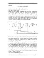
FIGURE 1 CONVENTIONAL DEHUMIDIFIER
COOLING
COIL
HEATING
COIL
FAN
With conventional dehumidification technology (Figure 1,
above), warm humid air, flows through a cooling coil
where it is cooled and dehumidified. The dehumidified
and cooled air is then reheated through a heating coil prior
to entering the conditioned space.
In the regenerative dehumidification technology (Figure
2, above), warm, humid air flows through the first pass of
an air-to-air heat exchanger for pre-cooling and
dehumidification by thermal exchange with the cooler
leaving air. The air then passes through a cooling coil for
final cooling and dehumidification. The dehumidified
and cooled air is then drawn back through the opposite
side of the air-to-air heat exchanger to be heated, prior to
entering the conditioned space.
FIGURE 2 REGENERATIVE DEHUMIDIFIER
FAN
PLATE HEAT
EXCHANGER
COOLING COIL
CONDENSED MOISTURE
As in conventional dehumidification, the regenerative
technology uses ordinary refrigerants or chilled water.
However, in the energy-efficient regenerative
dehumidifier, a lower temperature air enters the cooling
coil as a result of pre-cooling and dehumidification
through the air-to-air heat exchanger. This innovative
combination of an air-to-air heat exchanger with
conventional cooling coil results in reduced compressor
capacity, requiring half the energy for dehumidification
compared with conventional dehumidification systems.
DE/DH 1/7/2003
4
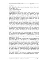
DH AND DE UNIT CONFIGURATIONS
DH—DEHUMIDIFIER ONLY
EVAPORATOR
SUPPLY
FAN
MSP
TM
DEHUMIDIFYING
COIL
DE—WITH ROTARY HEAT EXCHANGER
EVAPORATOR
EXHAUST
FAN
SUPPLY
FAN
HEAT
MSP
TM
DEHUMIDIFYING
COIL
ENTHALPY
ROTOR
Makeup air dehumidifier with rotary heat exchanger for
energy recovery.
DE—INTEGRAL UNIT
EVAPORATOR
EX HAUST
FAN
SUPPLY
FAN
COMPRESSOR
HEAT
MSP
TM
DEHUMIDIFYING
COIL
ENTHALPY
ROTOR
CONDENSER
Totally self-contained air-cooled packaged unit for
indoor or outdoor installation.
DE—WITH PLATE HEAT EXCHANGER
EXHAUS T
FAN
SUPPLY
FAN
HEAT
MSP
TM
DEHUMIDIFYING
COIL
PLATE
EXCHANGER
EVAPORATOR
Makeup air dehumidifier with plate heat exchanger for
energy recovery.
Features
• Split or packaged units
• Indoor & outdoor construction
• Air-cooled, water-cooled or chilled water
• Heat pumps—water and air source
• Double-wall construction
• Stainless steel drain pans
• Internally isolated fans
• Modular designs
• All voltage options
• Cooling option
Options
• Energy recovery ventilators—using plate or rotary
exchangers
• Hot water or steam heating coils
• Direct or indirect gas heating
• Electric heat
• Integral F&B coils
• Single point electrical connections
• Unit mounted disconnect switch
• Self-contained control system
• High efficiency MSP® heat exchangers
• Variable frequency drives
• Roof curbs—isolation and standard
DE/DH 1/7/2003
5
MAKEUP AIR DEHUMIDIFICATION DESIGN STRATEGY
Makeup air dehumidifiers should be sized to deliver a
desired dew point to the conditioned space. The delivered
dew point should not exceed the space dew point except
under maximum conditions. When outdoor conditions are
at “maximum moisture load” the space relative humidity
may be permitted to rise as high as 70%. The designer
should be aware that mold growth and other humidity
related problems would occur only under sustained high
humidity conditions. Therefore, a good design will allow
increased humidity during maximum load conditions.
ASHRAE publishes three design conditions with three
hours of occurrence for each. The worst condition for
humidity control is “maximum wet-bulb with mean
coincident dry bulb temperature” (WB/MCDB). Because
these conditions occur infrequently, it is wise to use a
coincident high indoor humidity to avoid “over-
designing”. Nautica recommends using design conditions
of WB/MCDB at 0.4% occurrence. Supply air dew point
should be equal to that of the room with a relative
humidity of 60% to 65%. This design strategy will result
in indoor humidity between 50% and 55% during
“normal” conditions.
Humidity is expressed in two ways; absolute and relative.
Relative humidity is a good measure of comfort in an
indoor environment because the temperature is stable.
However, outdoor air temperature is constantly changing
and relative humidity, by itself, is meaningless without
knowing its temperature.
Absolute humidity, on the other hand, only changes
when moisture is added or subtracted from air. It is a
more appropriate condition to work with in
humidification and dehumidification design. Absolute
humidity is expressed as dew point, grains/pound or
pounds/pound.
DATA ENTRY FORM
VENTILATION AIR CFM CFM Tables 1 & 2
SUMMER DB GR
INDOOR AIR CONDITIONS
WINTER DB GR
Table 3
SUMMER DB GR
OUTDOOR CONDITIONS
WINTER DB RH
Table 4
DE/DH 1/7/2003
6
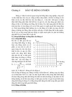
TABLE 1 – OUTDOOR AIR REQUIREMENTS FOR VENTILATION
Outdoor air Outdoor air
Application
Cfm
/person
Cfm
/sq ft
Application
Cfm
/person
Cfm
/sq ft
Food and Beverage Service
Specialty Shops
-----
Dining rooms 20 ----- Barber 15 -----
Cafeteria, fast food 20 ----- Beauty 25 -----
Bars, cocktail lounges 30 ----- Reducing salons 15 -----
Hotels, Motels, Resorts Dormitories Cfm/room
Florists 15 -----
Bedrooms ----- 30 Clothiers, furniture 0.30
Living rooms ----- 30 Hardware, drugs, fabric 15 -----
Baths ----- 35 Supermarkets 15 -----
Lobbies 15 ----- Pet shops 1.00
Conference rooms 20 -----
Sports and Amusement
-----
Assembly rooms 15 ----- Spectator areas 15 -----
Dormitory sleeping areas 15 ----- Game rooms 25
Gambling Casinos 30 ----- Ice arenas (playing areas) 0.50
Offices
----- Swimming pools (pool and deck area) 0.50
Office space 20 ----- Playing floors(gymnasium) 20 -----
Reception areas 15 ----- Ballrooms and discos 25 -----
Telecommunication centers and data entry 20 ----- Bowling alleys (seating areas) 25 -----
Conference rooms 20 -----
Theaters
-----
Public Spaces
Cfm/sq ft Ticket booths 20 -----
Corridors and utilities -----
0.05
Lobbies 20 -----
Public restrooms, cfm/wc or urinal 50 ----- Auditorium 15 -----
Locker and dressing rooms ----- 0.50 Stages, studios 15 -----
Smoking lounge 60 -----
Transportation
-----
Elevators ----- 1.00 Waiting rooms 15 -----
Retail Stores, Sales and Show Room Floors
----- Platforms 15 -----
Basement and street ----- 0.30 Vehicles 15 -----
Upper floors ----- 0.20
Workrooms
-----
Storage rooms ----- 0.15 Meat processing 15 -----
Dressing rooms ----- 0.20
Malls and arcades ----- 0.20
Shipping and receiving ----- 0.15
Warehouses ----- 0.05
Smoking lounge 60 -----
Table 1 prescribes supply rates of acceptable outdoor air required for acceptable indoor air quality. These values have been chosen to dilute human
bioeffluents and other contaminants with an adequate margin for safety and to account for health variations among people and varied activity levels. Source:
ASHRAE Standard 62-2001