Tài liệu Operating Fiber Loop Converters Over Multimode Fiber pptx
Bạn đang xem bản rút gọn của tài liệu. Xem và tải ngay bản đầy đủ của tài liệu tại đây (21.67 KB, 4 trang )
Application Note 1206
Telecommunications
Fiber Loop Converters are sometimes required to operate over multimode fiber because
an existing span of installed multimode fiber may already be in place between two points
requiring FLC transmission. The FLCs were designed for use over singlemode fiber, and
if there is a choice, singlemode fiber should be installed. However, FLC operation over
multimode fiber is possible and, in fact, is a functioning application with several custom-
ers. LAN applications over short distances have been successful. The following aspects of
this application require attention.
A 10 meter (33') singlemode jumper with a physical finish on the connector endfaces
should be installed in the FLC transmitter. This singlemode jumper can then be con-
nected to the multimode fiber in the span. To prevent higher order modes from being
launched directly into the multimode fiber, a minimum of 10 meters (33') of singlemode
fiber is required out of the transmitter.
The multimode fiber can terminate directly into the FLC’s receiver at the other end of
the span.
Ideally, the only connection in the span will be the junction from singlemode to
multimode. If fiber joining is required anywhere else in the span, fusion splicing is
recommended.
Because the connectors in a multimode span are not required to be in physical contact at
the fiber endfaces, Fresnel reflections and alignment mismatches can degrade perfor-
mance to an unacceptable level. If connectors are in the span, they should be of
singlemode quality with physically contacting, radius-polished fiber endfaces. Multimode
SMA and biconic fiber connectors are unacceptable. D4, SC, FC and ST
®
connectors can
be used, if the endface polish and the concentricity tolerances are singlemode quality.
The number of connectors should be kept to the absolute minimum.
Launch Conditions
Connections
in the Span
®
Operating Fiber Loop Converters
Over Multimode Fiber
2
Operating FLCs over Multimode Fiber
Application Note 1206
Multimode fiber has higher loss per distance properties than singlemode fiber. Tradi-
tional calculations of optical budget for the span will not take into account the pulse
spreading and interference resulting from sending a singlemode signal down a multi-
mode fiber. The optical budget for the DS3 FLC is 13 dB at 1300 nm wavelength. Standard
Corning 62.5 mm fiber has attenuation of 0.7 dB/km. This works out to a theoretical
capability of 18.5 km (11.5 miles) based on optical budget alone. When bandwidth is
considered, the theoretical distance limit decreases. Bandwidth is not a limiting factor
for T1/E1 FLCs and QFLCs. Bandwidth may become the limiting factor when the bit rate
increases to DS3 rates or above.
The bandwidth of the fiber, which is measured in the units of MHz-kilometers, should be
known. Standard Corning graded-index 62.5 micron core multimode fiber typically
exhibits a bandwidth of 400 MHz/km. This means that an FLC operating at 51.84 Mbps
(which translates into an analog rate of 25.92 MHz) is theoretically capable of transmit-
ting over a distance of 15.43 km (9.56 miles). However, more conservative distances are
recommended. See Table 1 (which lists the minimum of 200 MHz/km) and Table 2 for
the theoretical limits of the FLCs. The bandwidth cells of the fibers listed in the tables
are minimums. Fiber of greater bandwidth capacity is available from the manufactur-
ers. QLX modules operate at the same rates as the QFLC.
DS3 FLCs have been successfully implemented over a distance of 10.0 km (6.2 miles on
multimode fiber).
Both attenuation and bandwidth of the multimode fiber should be examined and the
limits calculated before installing FLCs and QLXs for use over multimode fiber. Charac-
terizing the fiber plant or records indicating the exact fiber type will help to determine
how well FLCs and QLXs can work over multimode fiber. Call ADC Application Engineer-
ing at 1-800-366-3889 before purchasing FLCs or QLXs for use over multimode fiber.
Optical Budget,
Bandwidth and Fiber
Properties
ADC CATALOG NUMBER
Multimode Fiber
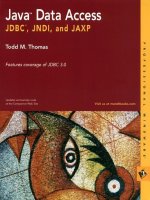
TABLE 1: Theoretical Span Calculation for FLCs Over Multimode Fiber
CORNING 50/125
Att.: 0.80 dB/km
BW: min. 400 MHz.km
Theoretical Capacity:
Attenuation: 16.2 km / 10.0 miles
Bandwidth: 15.4 km / 9.56 miles (25.920 MHz)
CORNING 62.5/125
Att.: 0.70 dB/km
BW: min. 200 MHz.km
Theoretical Capacity:
Attenuation: 18.5 km / 11.5 miles
Bandwidth: 7.71 km / 4.78 miles (25.920 MHz)
CORNING 100/140
Att.: 2.00 dB/km
BW: min. 100 MHz.km
Theoretical Capacity:
Attenuation: 6.50 km / 4.03 miles
Bandwidth: 3.85 km / 2.39 miles (25.920 MHz)
AT & T 62.5
Att.: 1.00 dB/km
BW: min. 500 MHz.km
Theoretical Capacity:
Attenuation: 13.0 km / 8.05 miles
Bandwidth: 19.2 km / 11.9 miles (25.920 MHz)
BerkTek 62.5/125
Att.: 1.00 dB/km
BW: 500 MHz.km
Theoretical Capacity:
Attenuation: 13.0 km / 8.05 miles
Bandwidth: 19.2 km / 11.9 miles (25.920 MHz)
T3/FLC DS3-B1LDFC(SC)
13 dB at 1300 nm
3
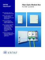
Operating FLCs over Multimode Fiber Application Note 1206
CORNING 50/125
Att.: 0.80 dB/km
BW: 400 MHz/km
CORNING 62.5/125
Att.: 0.70 dB/km
BW: 200 MHz/km
CORNING 100/140
Att.: 2.00 dB/km
BW: 100 MHz/km
AT&T 62.5
Att.: 1.00 dB/km
BW: 500 MHz/km
BerkTek 62.5/125
Att.: 1.00 dB/km
BW: 500 MHz/km
28.7 km
17.7 miles
32.8 km
20.3 miles
11.5 km
7.12 miles
23.0 km
13.6 miles
23.0 km
14.3 miles
T1/DFLC
F1544-20XR
23 dB/1300nm
27.5 km
17.0 miles
31.4 km
19.4 miles
11.0 km
6.81 miles
22.0 km
13.6 miles
22.0 km
13.6 miles
T1/QLX
QLX-
SPXSC(FC)A2
22 dB/1300nm
27.5 km
17.0 miles
31.4 km
19.4 miles
11.0 km
6.81 miles
22.0 km
13.6 miles
22.0 km
13.6 miles
T1/QFLC
QFC-
D3LDSC(FC)
22 dB/1300nm
ADC CATALOG
NUMBER
Multimode Fiber
27.5 km
17.0 miles
31.4 km
19.4 miles
11.0 km
6.81 miles
22.0 km
13.6 miles
22.0 km
13.6 miles
E1/DFLC
F2048-
20M(R)XR
22 dB/1300 nm
TABLE 2: TheoretIcal Span Calculation for FLCs Over Multimode Fiber
Contact ADC Application Engineering at 1-800-366-3889 for additional assistance.
Application Note 1206 12/94 Original © 1994 ADC Telecommunications, Inc. All Rights Reserved An Equal Opportunity Employer
Specifications published here are current as of the date of publication of this document. Because we are continuously improving our products,
ADC reserves the right to change specifications without prior notice. At any time, you may verify product specifications by contacting our
headquarters office in Minneapolis.
ADC Telecommunications, Inc.
4900 West 78th Street
Minneapolis, Minnesota 55435
FAX: (612) 946-3292
For U.S. Sales, Call Toll Free: 1-800-366-3891
®
Telecommunications
International Sales Offices: Belgium 32-2-721-5282 • United Kingdom
44-734-441955 • Montreal, Quebec (514) 677-9166 • Vancouver, BC
(604) 270-1675 • Toronto, Ont. (905) 629-3104 • Ottawa, Ont. (613)
596-9937 • Singapore 65-225-8228 • Venezuela 58-2-953-1684 •
Mexico City, Mexico 525-658-4519 • Sydney, Australia 61-2-975-1499