Tài liệu Fundamentals of Fiber Cable Management pptx
Bạn đang xem bản rút gọn của tài liệu. Xem và tải ngay bản đầy đủ của tài liệu tại đây (1.08 MB, 23 trang )
Fundamentals of
Fiber Cable Management
WHITE PAPER
8/05 • 10273
Fundamentals of Fiber Cable Management
3
www.adc.com • +1-952-938-8080 • 1-800-366-3891
Lower operations costs, greater reliability and flexibility in service offerings, quicker deployment of new
and upgraded services—these are the characteristics of a successful service provider in a competitive
global market. Service providers continue to build out high-bandwidth networks around the world.
These networks use a great deal of fiber—the medium that meets both their bandwidth and cost
requirements. But just deploying the fiber is not enough; a successful fiber network also requires a well
built infrastructure based on a strong fiber cable management system. Management of the fiber cables
has a direct impact on network reliability, performance, and cost. It also affects network maintenance
and operations, as well as the ability to reconfigure and expand the network, restore service, and
implement new services quickly. A strong fiber cable management system provides bend radius
protection, cable routing paths, cable accessibility and physical protection of the fiber network. If these
concepts are executed correctly, the network can deliver its full competitive advantages.
Introduction
Facing ever-increasing competition, service providers deploy fiber because of its high bandwidth and its
ability to deliver new revenue-generating services profitably.
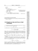
A look at the numbers clearly tells the bandwidth story. While twisted pair copper cable is limited in its
bandwidth capacity to around 6Mbps, and coaxial cable is limited to an STM-1 level of 155Mbps,
singlemode fibers are commonly used at STM-1 (155Mbps), STM-4 (622Mbps), STM-16 (2.5GPX), and
even higher levels around the world (see Table 1).
The use of fiber translates into more revenue for providers, especially from business customers who
demand high-bandwidth networks delivering voice, video and data at increased speed, assured service
levels and guaranteed security. A single dedicated E1 circuit to a corporation can easily generate around
15,468€ revenue per year. A single fiber operating at an STM-4 level carrying 480 E1 circuits can
generate as much as 5,160,000€ per year. Potential revenue varies by country, system usage, fiber
allocation and other factors, but the bottom line is clear: a single fiber cable can carry a larger amount
of revenue-producing traffic than a single twisted pair or coaxial cable can.
Service providers are pushing fiber closer and closer to the end user, whether that is fiber to the home
or to the desk. An increasing amount of an operator's revenue flows through the fiber. To realize fiber's
enormous advantage in revenue-producing bandwidth, fiber cables must be properly managed. Proper
management affects how quickly new services can be turned up and how easily the network can be
reconfigured. In fact, fiber cable management, the manner in which the fiber cables are connected,
terminated, routed, spliced, stored and handled, has a direct and substantial impact on the networks'
performance and profitability.
Fundamentals of Fiber Cable Management
Introduction
Signal Bit Rate Voice Medium
(Mbps) Channel
DS0 0,064 1
DS1 1,540 24
TWISTED PAIR
E1 2,040 30
DS2 6,310 96
E2 8,190 120
E3 34,000 480
COAXIAL CABLE
DS3 44,730 672
STS3 (STM-1) 155,520 2016
STS-1OC-1 51,840 627
(STM-1) STS-3/OC-3 155,520 2016
(STM-4) STS-12/OC-12 622,080 8064 FIBRE OPTIC CABLE
(STM-16) STS-48/OC-48 2488,320 32.256
STS-192/OC-192 9953,280 129.024
Table 1. Transmission hierarchies
8/05 • 10273
Fundamentals of Fiber Cable Management
4
www.adc.com • +1-952-938-8080 • 1-800-366-3891
There are four critical elements of fiber cable management: bend radius protection; cable routing paths;
cable access; physical protection. All four aspects directly affect the network's reliability, functionality,
and operational cost.
Bend Radius Protection
There are two basic types of bends in fiber—microbends and macrobends. As the names indicate,
microbends are very small bends or deformities in the fiber, while macrobends are larger bends
(see Figure 1).
The fiber's radius around bends impacts the fiber network's long-term reliability and performance.
Simply put, fibers bent beyond the specified minimum bend diameters can break, causing service failures
and increasing network operations costs. Cable manufacturers, Internet and telecommunications service
providers, and others specify a minimum bend radius for fibers and fiber cables. The minimum bend
radius will vary depending on the specific fiber cable. However, in general, the minimum bend radius
should not be less than ten times the outer diameter (OD) of the fiber cable. Thus a 3mm cable should
not have any bends less than 30mm in radius. Telcordia recommends a minimum 38mm bend radius for
3mm patch cords (Generic Requirements and Design Considerations for Fiber Distributing Frames,
GR-449-CORE, Issue 1, March 1995, Section 3.8.14.4). This radius is for a fiber cable that is not under
any load or tension. If a tensile load is applied to the cable, as in the weight of a cable in a long vertical
run or a cable that is pulled tightly between two points, the minimum bend radius is increased, due to
the added stress.
There are two reasons for maintaining minimum bend radius protection: enhancing the fiber's long-term
reliability; and reducing signal attenuation. Bends with less than the specified minimum radius will
exhibit a higher probability of long-term failure as the amount of stress put on the fiber grows. As the
bend radius becomes even smaller, the stress and probability of failure increase. The other effect of
minimum bend radius violations is more immediate; the amount of attenuation through a bend in a
fiber increases as the radius of the bend decreases. The attenuation due to bending is greater at
1550nm than it is at 1310nm—and even greater at 1625nm. An attenuation level of up to 0,5dB can
be seen in a bend with a radius of 16mm. Both fiber breakage and added attenuation have dramatic
effects on long-term network reliability, network operations costs, and the ability to maintain and grow
a customer base.
In general, bend radius problems will not be seen during the initial installation of a fiber distribution
system (FDS), where an outside plant fiber cable meets the cable that runs inside a central office or
headend. During initial installation, the number of fibers routed to the optical distribution frame (ODF) is
usually small. The small number of fibers, combined with their natural stiffness, ensures that the bend
radius is larger than the minimum. If a tensile load is applied to the fiber, the possibility of a bend radius
violation increases. The problems grow when more fibers are added to the system. As fibers are added
on top of installed fibers, macrobends can be induced on the installed fibers if they are routed over an
unprotected bend (see Figure 2). A fiber that had been working fine for years can suddenly have an
increased level of attenuation, as well as a potentially shorter service life.
Fundamentals of Fiber Cable Management
The Four Elements of Fiber Cable Management
Figure 1. Microbends and macrobends
Point at Which
Light is Lost
From Fiber
Optical Fiber
Light Pulse
Area
in Which
Light is
Lost From
Fiber
Optical Fiber
Light Pulse
Radius of
Curvature
Microbend
Macrobend
8/05 • 10273
Fundamentals of Fiber Cable Management
5
www.adc.com • +1-952-938-8080 • 1-800-366-3891
The fiber used for analogue video CATV systems presents a special case. Here, receiver power level is
critical to cost-effective operation and service quality, and bend radius violations can have different but
equally dramatic effects. Analogue CATV systems are generally designed to optimize transmitter output
power. Due to carrier-to-noise-ratio (CNR) requirements, the receiver signal power level is controlled,
normally to within a 2dB range. The goal is for the signal to have enough attenuation through the fiber
network, including cable lengths, connectors, splices and splitters, so that no attenuators are needed at
the receiver. Having to attenuate the signal a large amount at the receiver means that the power is not
being efficiently distributed to the nodes, and possibly more transmitters are being used than are
necessary. Since the power level at the receiver is more critical, any additional attenuation caused by
bending effects can be detrimental to picture quality, potentially causing customers to be dissatisfied and
switch to other vendors.
Since any unprotected bends are a potential point of failure, the fiber cable management system should
provide bend radius protection at all points where a fiber cable makes a bend. Having proper bend
radius protection throughout the fiber network helps ensure the network's long-term reliability, thus
helping maintain and grow the customer base. Reduced network down time due to fiber failures also
reduces the operating cost of the network.
Cable Routing Paths
The second aspect of fiber cable management is cable routing paths. This aspect is related to the first as
improper routing of fibers by technicians is one of the major causes of bend radius violations. Routing
paths should be clearly defined and easy to follow. In fact, these paths should be designed so that the
technician has no other option than to route the cables properly. Leaving cable routing to the
technician's imagination leads to an inconsistently routed, difficult-to-manage fiber network. Improper
cable routing also causes increased congestion in the termination panel and the cableways, increasing
the possibility of bend radius violations and long-term failure. Well-defined routing paths, on the other
hand, reduce the training time required for technicians and increase the uniformity of the work done.
The routing paths also ensure that bend radius requirements are maintained at all points, improving
network reliability.
Additionally, having defined routing paths makes accessing individual fibers easier, quicker and safer,
reducing the time required for reconfigurations. Uniform routing paths reduce the twisting of fibers and
make tracing a fiber for rerouting much easier. Well-defined cable routing paths also greatly reduce the
time required to route and reroute patch cords. This has a direct effect on network operating costs and
the time required to turn-up or restore service.
Fundamentals of Fiber Cable Management
The Four Elements of Fiber Cable Management
Maintaining proper radius
Fiber Patch Cord
Initial Installation
Violating minimum bend radius
Fiber Patch Cord
After Future
Installation
Figure 2. Effect of adding fibers
8/05 • 10273
Fundamentals of Fiber Cable Management
6
www.adc.com • +1-952-938-8080 • 1-800-366-3891
Cable Access
The third element of fiber cable management is the accessibility of the installed fibers. Allowing easy
access to installed fibers is critical in maintaining proper bend radius protection. This accessibility should
ensure that any fiber can be installed or removed without inducing a macrobend on an adjacent fiber.
The accessibility of the fibers in the fiber cable management system can mean the difference between a
network reconfiguration time of 20 minutes per fiber and one of over 90 minutes per fiber. Accessibility
is most critical during network reconfiguration operations and directly impacts operation costs and
network reliability.
Physical Fiber Protection
The fourth element of fiber cable management is the physical protection of the installed fibers. All fibers
should be protected throughout the network from accidental damage by technicians and equipment.
Fibers routed between pieces of equipment without proper protection are susceptible to damage, which
can critically affect network reliability. The fiber cable management system should therefore ensure that
every fiber is protected from physical damage.
Fundamentals of Fiber Cable Management
The Four Elements of Fiber Cable Management
All four elements of fiber cable management come together in the fiber distribution system, which
provides an interface between outside plant (OSP) fiber cables and fiber optic terminal (FOT) equipment
(see Figure 3). A fiber distribution system handles four basic functions: termination, splicing, slack
storage, and housing of passive optical components.
Non-Centralized System
A fiber distribution system can be non-Centralized or Centralized. A non-Centralized fiber distribution
system is one in which the OSP fiber cables come into the office and are routed to an ODF located near
the FOT equipment they are serving. Each new OSP fiber cable run into the office is routed directly to the
ODF located nearest the equipment with which it was originally intended to work (see figure 4). This is
how many fiber networks started out, when fiber counts were small and future growth was not
anticipated. As network requirements change, however, the facilities that use the OSP fibers also change.
Changing a particular facility to a different OSP fiber can be very difficult, since the distance may be great
and there tends to be overlapping cable routing. While a non-Centralized fiber distribution system may
initially appear to be a cost-effective and efficient means to deploy fiber within an office, experience has
shown that major problems with flexibility and cable management will arise as the network evolves and
changes. These reasons suggest the need for a Centralized fiber distribution system.
7
www.adc.com • +1-952-938-8080 • 1-800-366-3891
Fundamentals of Fiber Cable Management
Fiber Distribution Systems and the ODF
KEY
ODF: Optical
Distribution Frame
FOT: Fiber Optic
Terminal Equipment
FUT: Future Frame
(Growth)
FUT
FOT
FOT
ODF
FOT
FOT
FOT
FOT
FUT
FUT
FUT
FUT
FUT
FOT
ODF
FOT
FOT
FOT
FUT
FUT
FOT
FOT
ODF
FOT
FOT
FOT
FOT
FOT
FOT
ODF
FOT
FOT
FOT
FOT
FOT
FUT
FUT
FUT
FUT
FOT
FOT
FOT
FOT
ODF
FOT
FOT
FOT
FUT
FUT
FUT
FUT
FUT
New
location
Old
location
OSP
Cables
Fiber Patch Cord
Frame
lineup
Figure 4. Non-Centralized office floor plan
for fiber distribution network layout
ODF
(FOT)
O/E
(FOT)
O/E
DSX
E3
1.3
MUX
DSX
E1
Switch
Digital Cross
Connect
(DCX)
OSP
Cable
Fiber
Coaxial
Twisted Pair
Central Office or Headend
Figure 3. Optical distribution frame (ODF) functionality
8/05 • 10273
Fundamentals of Fiber Cable Management
8/05 • 10273
Fundamentals of Fiber Cable Management
8
www.adc.com • +1-952-938-8080 • 1-800-366-3891
Centralized System
A Centralized fiber distribution system provides a network that is more flexible, more cost-efficient to
operate and that has better long-term reliability. A Centralized fiber distribution system brings all OSP
fibers to a common location at which all fiber cables to be routed within the office originate (see Figure
5). A Centralized fiber distribution system consists of a series of optical distribution frames (ODF), also
known as fiber distribution frames (FDF). The Centralized ODF allows all OSP fibers to be terminated at a
common location, making distribution of the fibers within the OSP cable to any point in the office easier
and more efficient. Having all OSP fiber in one location and all FOT equipment fibers coming into the
same general location reduces the time and expense required to reconfigure the network in the event of
equipment changes, cable cuts, or network expansion.
Let's return now to the four basic functional requirements of any fiber distribution system: terminations,
splicing, slack storage, and housing of passive optical components.
In order for the signal to get from one fiber to another, the cores of the two fibers need to be joined,
brought into near-perfect alignment. The measurements that determine the quality of the junction are
insertion loss and return loss. Insertion loss (IL) is a measure of the power that is lost through the
junction (IL = -10log(Pout/Pin)), where P is power. An insertion loss value of 0,3dB is equivalent to about
7-percent of the power being lost. Return loss (RL) is a measure of how much power is reflected back to
the source from the junction (RL = 10log (Pin/Pback)). A return loss value of 57dB is equivalent to
0,0002-percent of the light being reflected back. There are two means of joining fibers in the industry
today: connector terminations and splices
Terminations
Connector termination in fiber optics refers to the physical joining, using a mechanical connector, of two
separate fibers, with the goal of having 100-percent signal transfer. Connector terminations used for
junctions are meant to be easily reconfigurable, to allow easy connection and reconnection of fibers.
There are several fiber connectors available in the industry today; the most commonly used singlemode
types are SC, FC and LC. Typical singlemode ultra polish connectors will provide insertion loss values of
<0,3dB and return loss values of >52dB, while singlemode angled polish connectors have insertion loss
values of <0,2dB and return loss values of >55dB.
Reliable operation of connectors depends on the proper geometry of the convex polished ferrule
endface. The following parameters are routinely checked by interferometric inspection: radius of
curvature, apex offset, fiber projection/undercut, polishing angle (see Figure 6).
Fundamentals of Fiber Cable Management
Fiber Distribution Systems and the ODF
ODF
ODF
ODF
ODF
ODF
ODF
ODF
FUT
FUT
FUT
FUT
FUT
FUT
FOT
FOT
FOT
FOT
FOT
FOT
FOT
FOT
FOT
FOT
FUT
FUT
FUT
FOT
FOT
FOT
FOT
FOT
FOT
FOT
FOT
FOT
FUT
FUT
FUT
FUT
FOT
FOT
FOT
FOT
FOT
FOT
FOT
FOT
FOT
FOT
FOT
FUT
FUT
OSP
Cables
Fiber Patch Cord
KEY
ODF: Optical
Distribution Frame
FOT: Fiber Optic
Terminal Equipment
FUT: Future Frame
(Growth)
Figure 5. Centralized fiber distribution network layout
8/05 • 10273
Fundamentals of Fiber Cable Management
9
www.adc.com • +1-952-938-8080 • 1-800-366-3891
A connector is installed onto the end of each of the two fibers to be joined. Singlemode connectors are
generally factory-installed, to meet requirements for optical performance and long-term reliability. The
junction is then made by mating the connectors to each side of an adapter. The adapter holds the
connectors in place and brings the fibers into alignment (see Figure 7).
The adapters are housed within a termination panel, which provides a location to safely house the
adapter/connector terminations and allows easy access to installed connectors. Fiber termination panels
typically house from twelve to 144 terminations. Termination panels should adapt easily to any standard
style of connector/adapter. This allows easy future growth and also provides more flexibility in evolving
network design. Fiber cable management within the termination panel is critical.
Cable management within a termination panel must include proper bend radius protection and physical
routing paths. The fibers should have bend radius protection along the route from the adapter port to
the panel exit location. The path the fiber follows in getting to the panel exit should also be very clear
and well defined. Most cable management problems in termination panels arise from improper routing
of patch cords. Improper fiber routing within the panels can make access to installed connectors very
difficult, and can cause service-affecting macrobends on adjacent fibers. Connectors should also be
removable without the use of special tools, which can be costly and easily lost or left behind. Proper
fiber cable management in the termination panel improves network flexibility, performance and reliability
while reducing operations costs and system reconfiguration time.
When fiber is used in the local serving loop, such as in hybrid fiber/coax networks or fiber-fed digital
loop converters (DLCs), backup fibers run to the optical network unit (ONUs) or to the DLCs. These
fibers are provided in case a technician breaks the active fiber or damages the connector during
installation and maintenance. In the event of such an occurrence, the signal has to be rerouted from the
original active fiber to the backup fiber. This rerouting is done at the OSP termination panel within the
ODF. While the fiber appearances on the termination panel are generally located either adjacent to each
Fundamentals of Fiber Cable Management
Fiber Distribution Systems and the ODF
Adapter
Fiber Connector
Fiber Patch Cord
Fiber Connector
Fiber Patch Cord
Termination Panel
Figure 7. Fiber terminations
Figure 6.
8/05 • 10273
Fundamentals of Fiber Cable Management
10
www.adc.com • +1-952-938-8080 • 1-800-366-3891
other or within a few terminations of each other, this reconfiguration should not jeopardize the integrity
of the other installed circuits. If installed fibers must be moved in order to access the target connector,
then the probability of inducing a bending loss in those adjacent fibers is increased. And that loss could
be enough to cause a temporary service outage. These effects are especially pronounced in CATV
systems, in which the system attenuation is adjusted to an optimal power level at the receiver to provide
the best picture quality. Enabling easy access to individual terminations without disturbing other fibers is
an important feature of a termination panel.
Connector Cleaning
Reliable optical networks require clean connectors. Any time one connector is mated to another, both
connectors should be properly cleaned and inspected. Dirty connectors are the biggest cause of
increased back-reflection and insertion loss in connectors, including angled polish connectors. A dirty
ultra polish connector with a normal return loss of >55dB can easily have >45dB reflectance if it is not
cleaned properly. Similar comparisons can be made with angled polish connectors. This can greatly affect
system performance, especially in CATV applications where carrier-to-noise ratios (CNR) are directly
related to signal quality.
In order to ensure that both connectors are properly cleaned, the termination panel must allow them
both to be easily accessed. This easy access has to be for both the patch cord connector and the
equipment or OSP connector on the back side of the termination panel. Accessing these connectors
should not cause any significant loss in adjacent fibers.
A system that allows uncomplicated access to these connectors has much lower operating costs and
improved reliability. Without easy access to connectors, technicians will take more time to perform their
work, delaying implementation of new services or redeployment of existing services. Dirty connectors
can also jeopardize the long-term reliability of the network, because dirt and debris can be embedded
into the endface of the connector, causing permanent, performance-affecting damage.
Splicing
The other means of joining two fibers is a splice. Splicing in fiber optics is the physical joining of two
separate optical fibers with the goal of having 100-percent signal transfer. Splicing connections are
meant to be permanent, non-reconfigurable connections. There are two basic splicing methods in use
today: mechanical and fusion (see Figure 8).
Mechanical splicing involves the use of an alignment fixture to bring and hold two fibers in alignment.
Mechanical splices typically give insertion loss values of <0.15dB with return loss values of >35dB and
involve the use of an index-matching gel. Fusion splicing uses an electric arc to “weld” two fibers
together. Fusion splices typically have insertion loss values of <0.05dB and return loss values of >70dB.
Whichever splicing type is used, the ODF needs to provide a location to store and protect the splices.
The splicing function can be performed on the ODF (on-frame splicing) or in a location near the place at
which the OSP cables enter the building, such as the cable vault (off-frame splicing). We will discuss on-
frame versus off-frame splicing later in this paper. In either situation, the splice enclosure or panel
provides a location to store all splices safely and efficiently. The individual splices are housed within a
splice tray, generally holding between 12 and 24 splices. The splice trays in turn are housed within a
Fundamentals of Fiber Cable Management
Fiber Distribution Systems and the ODF
OSP Cable
Splice
Fiber Pigtail
Termination Panel
Splice Enclosure
Figure 8. Fiber splicing