Tài liệu Choosing the right connector pdf
Bạn đang xem bản rút gọn của tài liệu. Xem và tải ngay bản đầy đủ của tài liệu tại đây (199.31 KB, 4 trang )
WHITE PAPER
Choosing the right connector
APC vs. UPC
Choosing the right connector
Page 2
The choice between angle-polished connectors (APCs) and ultra-polished connectors (UPCs) can make a significant impact
on how a particular network will perform. There are several considerations to make, including the network design or
purpose and the types of services that will be transported over the fiber. This paper will compare and contrast these two
categories of connectors, highlighting their differences in terms of physical appearance, insertion loss and return loss
characteristics, as well as their overall performance in particular applications.
Passive Optical Network (PON) infrastructures deployed in fiber-to-the-premises (FTTP) networks require numerous fiber
connections to achieve the distribution of services to multiple homes. Although splicing has its place in these systems, use
of reliable angle-polished connectors (APCs) provides numerous advantages in terms of overall network flexibility, testing
and troubleshooting. For more detail regarding connector choice in PON video applications, please see the white paper
Connectors in FTTP Networks: Which Connector Do I Use in My FTTP Network? Literature #103178AE on www.adc.com.
Historically, UPCs have been the top performers, particularly with regard to insertion loss. For that reason, they are
considered the legacy connector and have been deployed in many networks to typically handle digitally-transmitted
information. However, due to the improved manufacturing techniques being used today, APC’s are now on par with UPCs
in terms of insertion loss.
There are many other benefits provided through the use of APCs, and each should be carefully considered during the
network design process– particularly, within the FTTX network architecture, where numerous fiber connections are
required to achieve the distribution of multiple services (triple and quadruple play) to multiple customers.
Physical attributes
The generally accepted color code for connector bodies and/or boots is beige for multimode fiber, blue for singlemode
fiber, and green for APC connectors. UPC connectors are easily identifiable by their blue color on the connector boot.
Both are available in SC (most common), LC
®1
, and FC style connectors.
The major physical difference between APCs and UPCs is the endface geometry. The UPC ferrule endface radius is
polished at an 8° angle while UPC connectors are polished at a 0° angle. The significance of this 8° angle becomes
apparent when addressing return loss issues, which will be discussed later in this paper.
Some UPC connectors are aligned with adapters that have phosphor bronze alignment sleeves. APC connectors require
ceramic zirconia alignment sleeves; and most off-the-shelf singlemode connectors—including preconnectorized panels—
will consist of ceramic sleeves. For UPC connectors, customers have a choice of either alignment sleeve material, but
zirconia is recommended for better performance. In fact, many major carriers have standardized with the zirconia sleeve
when using UPC connectors. ADC recommends zirconia for both APC and UPC connectors. Zirconia will typically provide
better alignment, insertion loss, and overall performance—particularly with temperature fluctuations.
Standards
Today, the SC connector type is standard in both the inside plant and the outside plant applications. The standard that
dictates the rules for outside plant is GR-326. Specifications from GR-326, Issue 3 are noted below:
1
LC is a registered trademark of OFS.
SC UPC Connector Specifications
Max 0.2 dB Insertion Loss (IL) (0.3 dB change over •
temperature) Tuned Connectors
Min Intramated Return Loss (ORL) 50 dB, Typical –58 dB•
Open RL 15 dB Typical•
SC APC Connectors
Typically higher IL (0.35 dB)•
Similar Temperature Implications•
Min ORL: 65 dB (67 dB open)•
Choosing the right connector
Page 3
Insertion Loss
The performance difference between APCs and UPCs begins with insertion loss. Insertion loss is defined as the measurement
for the amount of optical power lost through a mated connector pair. The connector insertion loss can be used with the
cable length loss to determine the allowable loss budget for an installed link. The formula for insertion loss is:
In the past, low insertion loss using APC connectors was difficult to achieve due to air gaps in the apex offsets which
caused substantial loss. However, due to improved connector designs and manufacturing processes, insertion loss
differences between APC and UPC connectors have diminished.
Today, the factors that relate to insertion loss are the same for both connector types. All four of these factors are
identical for today’s APC and UPC connectors.
• outsidediameter(OD)ofthefiber
• concentricityofthefibercore
• insidediameter(ID)oftheferrule
• concentricityoftheferrule’sID
Return Loss
The more significant performance characteristic between
APC and UPC connectors is their return loss. Return loss is a
measurement of the light reflected back to the source at an
optical interface. The formula for return loss in optics is:
RL= -10xLog(P
R
/P)
where P
R
= power reflected at connector interface
The APC connectors are superior UPC’s in this performance
category because of their angle-polished endface geometry.
When light is reflected at the connector interface of a UPC
connector, it is reflected straight back at the source, increasing
the return loss value. However, when the same signal passes
through the APC connector, the 8° angle causes the reflected
light to be absorbed by the cladding material.
The value of return loss for mated APCs in the field will typically
be greater than 70 dB. For a UPC connection, it is normally
> 50 to 55 dB. When connectors are unmated—such as
unused ports in an FTTP distribution frame—the return loss for
APC connectors is 55 dB or greater, compared to UPCs that
will be in the neighborhood of 14 dB. This is an important
consideration for building today’s FTTX architectures. (get
confirmation on these numbers in this last paragraph)
With APC connectors, a slight 8° angle is introduced to the end
face allowing improved performance at the fiber/air interface.
This improve performance is due to limiting the reflectance
upstream, back into the downstream optical signal. When reflecting an analog optical signal into the initial downstream
signal, two things occur: the reflected signal tends to degrade or attenuate the downstream signal, and there is a cross
modulating effect in the analog signals where when converting back to an analog RF signal.
For systems such as RF video, the APC is preferred because these particular systems are extremely sensitive to any back
reflections from connectors within the network. In general, UPCs are deployed in transport systems designed for digital
signal transport, while APCs are preferred for RF video signal transport. APC is also preferred, where there are open ports
at the other end of splitters—very typical in FTTP network designs.
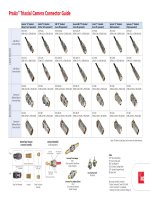
UPC Polish
Light is reflected back down to the core
Return Loss = 57 dB
(Adequate for most applications)
8° Angled Polish
Light is reflected into the cladding
Return Loss = 60 dB
(0.0001% of power reflected back)
(ideal for video and single fiber applications)
dB= -10log
10
Output Power
Input Power
WHITE PAPER
Website: www.adc.com
FromNorthAmerica,CallTollFree:1-800-366-3891•OutsideofNorthAmerica:+1-952-938-8080
Fax:+1-952-917-3237•ForalistingofADC’sglobalsalesofficelocations,pleaserefertoourwebsite.
ADC Telecommunications, Inc., P.O. Box 1101, Minneapolis, Minnesota USA 55440-1101
Specifications published here are current as of the date of publication of this document. Because we are continuously
improving our products, ADC reserves the right to change specifications without prior notice. At any time, you may
verify product specifications by contacting our headquarters office in Minneapolis. ADC Telecommunications, Inc.
views its patent portfolio as an important corporate asset and vigorously enforces its patents. Products or features
contained herein may be covered by one or more U.S. or foreign patents. An Equal Opportunity Employer
105662AE 3/08 Original © 2008 ADC Telecommunications, Inc. All Rights Reserved
Endface Geometry Issues
A brief discussion of APC endface geometry is also important for this paper in showing the strides that
have been made recently that make APCs the connectors of choice in outside plant and passive optical
network (PON) systems. During the manufacturing process, it is critical to control the endface geometry
parameters – apex offset, radius of curvature, and fiber height.
Preventing ferrule rotation that can change the apex offset of an APC connector to an unacceptable
standard has been a critical manufacturing issue. Changing and inconsistent interfaces, which allow
ferrule rotation about the ferrule axis, have the potential to create air gaps between the mated pair
fiber cores. This results in significantly degraded, if not interrupted, transmission performance.
ADC has developed an anti-rotational feature on its APC connectors that corrects ferrule rotation.
These features force the ferrule back into its original position if the ferrule is rotated either clockwise
or counter-clockwise within the housing. This guarantees that apex measurements will be maintained
throughout the life of the connector, regardless of how many matings and unmatings are performed.
Conclusion
The manufacturing techniques used today have greatly improved the performance for both the UPC
and APC connectors. Most advertised insertion loss characteristics range from 0.14 to 0.18 dB for both
connector types, When considering your unique network design, the APC connector is a good all-
around connector choice, although the decision will ultimately come down to return loss requirements.
In the end, ADC can help you examine all the considerations and issues regarding which connector—
the APC or UPC—will best perform in your unique deployment scenario.