Tài liệu Connectors in FTTP Networks Which Connector Do I Use in My FTTP Network? doc
Bạn đang xem bản rút gọn của tài liệu. Xem và tải ngay bản đầy đủ của tài liệu tại đây (1.73 MB, 8 trang )
WHITE PAPER
Connectors in FTTP Networks
Which Connector Do I Use in
My FTTP Network?
Which Connector
Do I Use in My FTTP Network?
In Fiber-To-The-Premise (FTTP) configurations, before one can choose the proper
fiber connector, it is important to understand some of the basic terminology and
make-up of the connectors as well as the type of video delivery system that is to
be utilized.
The Connector
A Connector is a device used to provide a semi-permanent link between
two optical fibers. Connectors must be able to maintain good optical contact
between the fibers at the connector interfaces. In theory, only the cross sectional
face of the two fibers need to touch, hence the term Physical Contact (PC)
connector is used.
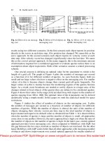
The basic components of a connector include the body, the ferrule, the
barrel (coupling nut/insert), and the boot. The body is the physical shell of
the connector, which houses the mechanism used to secure the fiber to the
connector. The ferrule is the long cylinder-like piece, which extends from the
body and provides protection and alignment of the fiber. Ferrules can be made
of composite materials, stainless steel, or ceramic. These material types provide
for a wide range in cost and performance values. The barrel is the plastic or
metal screw applicator or insert, which provides the method of attaching some
connector types (FC, SMA, SC, D4, Bionic) to their mating couplers. And finally
there is the boot, the small plastic strain relief that provides protection for the
fiber entering the rear of the connector body.
Key performance values in connectors include Insertion Loss, Reflectance, Core
Alignment (Apex Offset), and End Face Polishing. Insertion Loss is the measure
of reduction in signal caused by inserting a component, such as a connector,
into the optical pathway. Insertion loss is measured in decibels (dB), with a lower
dB reading having better performance standards, i.e. (0.10dB) is better than
(0.20dB). Reflectance is the measurement of light reflected from the cleaved or
polished fiber end at the glass/air interface. Reflectance is expressed in dB relative
to the incident signal. This value is important because some active component
systems are sensitive to light reflecting back into them, such as analog video.
Similar terms are back reflection and optical return loss (ORL). Again a lower
reading is better, i.e. (-50dB) is better than (-40dB), and you will see below, that
the Angled Physical Contact (APC) connectors have the lowest reading in all the
connector configurations.
Page 3
Alignment of the fiber cores is extremely important when connectorizing two fibers.
Two Important Alignment Issues in Connector Performance:
• Maintain Fiber to Fiber Contact
• Minimize Chance for Optical Degradation
– Potential air gap at elevated temperatures.
– Opportunity for debris migration
With single-mode core diameters approaching 8um, accurate core alignment is imperative. Finally there is End Face
Polishing. The End Face of the connector refers to the circular cross-section of the fiber where light is emitted and
received. By proper polishing of the connector, the geometrical properties of the end-face can be enhanced to provide
optimum fiber coupling. As connectors get worn, scarred, or contaminated, these geometric properties change resulting
in increased attenuation and loss of signal strength.
To improve upon the physical performance values at the connection point, there are several options to choose from.
One of the best ways to provide ultimate connector performance is to terminate the fiber with factory connectorized
pigtails. A pigtail is nothing more than a factory terminated connector with a short piece of fiber that can be fusion
or mechanically spliced onto the fiber cable. Another method is by selecting high performance polishing techniques
and/or utilizing Angled Physical Contact (APC) connectors. Obviously not all connectors are created equal. Beside field
termination polishing, which has been a tried and true method of terminating fiber, there are various grades of polished
connectors available from the factory. Typical field terminated Physical Contact connectors will have a reflectance of (<
-35dB) while an Ultra Physical Contact (UPC) connector will have a reflectance value approaching (<-55dB). Lastly by
introducing a small angle to the end face (APC connectors), the reflectance properties of the connector can be improved
to (<-65dB) which as we will see is important for an analog video overlay.
The Network
To understand why APC connectors are used in a PON optical network, it is important to understand the theory and
technology involved when converting an analog RF video signal to an analog optical signal. First, the signal remains in an
analog format and is not digitized. The inherent qualities of an analog RF video signal remain when converted the optical
signal, but there are some disturbing effects when a high optical power is applied to the signal. The characteristics of a
video overlay (analog video) applied to Passive Optical Networking (PON) technology is such that the tri-plexer within the
Optical Network Termination (ONT) that receives the 1550 nm optical signal converts the optical signal directly back into
an analog RF signal.
To start from the beginning, the video source is first amplified electrically, and then is converted to an optical signal. This
optical signal is then amplified through a cascade of erbium-doped fiber amplifiers (EDFAs); this cascade is also referred to
as a video optical line termination (V-OLT). Passive wavelength division multiplexing (WDM) is then used to combine the
amplified video signal onto the PON. The WDM filter is not a standard 1310 nm/1550 nm filter; instead, it is designed to
route 1310 nm and 1490 nm wavelengths to the OLT and ONT respectfully and the 1550 nm wavelength to the ONT.
Which Connector Do I Use in My FTTP Network?
Page 4
The ONT is also different; it is designed to receive and route the 1550 nm wavelength to a video optical receiver called
the tri-plexer, that converts the analog optical signal directly back to the radio frequency (RF) analog signal for connection
to the coaxial home wiring. The primary advantage of analog format is that it can be displayed on existing televisions
without the need for a set-top box (STB) converter. Digital format, on the other hand, requires an STB for each television.
One should not confuse the term digital TV with Video over IP (Digital Format). (They are not the same and the subject of
another white paper.)
Video Performance
Video performance is the quality of each channel's picture. For analog channels, three primary metrics have been
established to quantitatively assess picture quality: carrier-to-noise ratio (CNR), composite second order (CSO), and
composite triple beat (CTB). CNR measures the level of the video carrier signal relative to the noise. A poor CNR appears
as “snow” in the picture. CSO and CTB measure the level of coherent “beats” formed by mixing the individual channels,
relative to each video carrier's level. Poor CSO and CTB appear as lines and patterns in the picture.
Based on these metrics, the Federal Communications Commission (FCC) in North America has established minimum
standards for video quality when providing analog video service. The minimum standards are CNR greater than
or equal to 43 dB, CSO less than or equal to –51 dB, and CTB less than or equal to –51 dB. The Society of Cable
Telecommunication Engineers (SCTE) has established a standard of not worse than –53 dB for CSO and CTB, a level that
produces video imperfections that many consider to be imperceptible. While the FCC and SCTE requirement for CNR is
43 dB, most CATV providers seek to deliver better video quality, with a CNR greater than or equal to 47 dB.
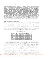
The primary reason for amplifying the original optical signal is such that the when the ONT receives the 1550 nm
wavelength, the receiver sensitivity is typically set between –6.5 and zero dBm so a carrier-to-noise ratio of 48 dB can be
realized. It has been shown that the best CNR metrics are between 46 dB and 52 dB (see graph below).
Which Connector Do I Use in My FTTP Network?
Figure 2. CNR Levels based upon Optical Receiver Levels
Page 5
Which Connector Do I Use in My FTTP Network?
Path Loss
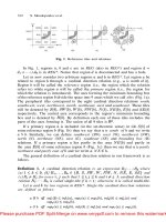
The video optical path begins at the output of the EDFA and ends at the input of the ONT. It consists of a WDM Filter
in the CO, optical fiber, couplers, splices, and connectors. (See Figure 3.) Knowing the quantity and loss characteristics
of each component, it is simple math to arrive at the total path loss. A typical path loss might look something like that
shown in Table 1.
Quantity Unit
1550 nm
Wavelength
Loss/Unit Loss
Optical Fiber 20 km 0.22 4.4
Couplers 1 ea 17.1 17.1
Connectors 4 ea 0.3 1.2
Splices 10 ea 0.04 0.4
WDM Filter 1 ea 0.5 0.5
Margin 0.5
TOTAL 24.1
Required EDFA Output Power
With the path loss calculated as in Table 1, it is now easy to determine the EDFA output power necessary to achieve the
optimum receiver level. Based upon table 1, and a 20 km PON, the EDFA output power must be at least 20.1 dBm (–4
dBm + 24.1 dBm).